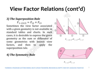
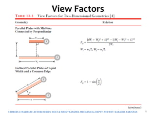
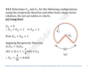
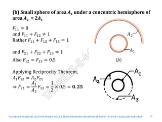
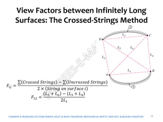
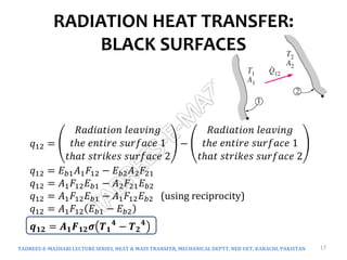
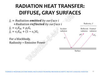
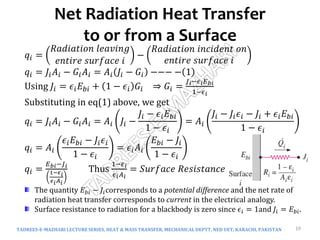
ME 315 HEAT AND MASS TRANSFER
Dr. Mubashir Ali Siddiqui
Mechanical Engineering Department
NED University of Engineering & Technology
Karachi, Pakistan
TADREES-E-MAZHARI LECTURE SERIES, HEAT & MASS TRANSFER, MECHANICAL DEPTT, NED UET, KARACHI, PAKISTAN 1
Chapter 13
Radiation Exchange Between
Surfaces
TADREES-E-MAZHARI LECTURE SERIES, HEAT & MASS TRANSFER, MECHANICAL DEPTT, NED UET, KARACHI, PAKISTAN 2
View Factor, Shape Factor
Radiation Heat Transfer : Black Surfaces
Radiation Heat Transfer : Diffuse, Gray Surfaces
Net Radiation Heat Transfer to or from a Surface
Net Radiation Heat Transfer between Any Two Surfaces
Radiation Heat Transfer in Three-Surface Enclosures
Surface Resistance
Space Resistance
Radiation Thermal Network
View Factor
TADREES-E-MAZHARI LECTURE SERIES, HEAT & MASS TRANSFER, MECHANICAL DEPTT, NED UET, KARACHI, PAKISTAN 3
View Factor
TADREES-E-MAZHARI LECTURE SERIES, HEAT & MASS TRANSFER, MECHANICAL DEPTT, NED UET, KARACHI, PAKISTAN 4
Radiation heat transfer between surfaces depends on the
orientation of the surfaces relative to each other as well as their
radiation properties and temperatures.
View factor – Takes into account the effects of orientation on
radiation heat transfer between two surfaces. It is a purely
geometric quantity and is independent of the surface properties
and temperature. It is also called the shape factor, configuration
factor, and angle factor.
Fij : the fraction of the radiation leaving surface i that strikes surface j
directly
View Factor
Examples
TADREES-E-MAZHARI LECTURE SERIES, HEAT & MASS TRANSFER, MECHANICAL DEPTT, NED UET, KARACHI, PAKISTAN 5
View Factor Relations
TADREES-E-MAZHARI LECTURE SERIES, HEAT & MASS TRANSFER, MECHANICAL DEPTT, NED UET, KARACHI, PAKISTAN 6
1) Reciprocity Relation
𝐴1𝐹12 = 𝐴2𝐹21
It allows the calculation of a view factor from a knowledge of the
other.
2) Summation Rule
𝑗=1
𝑁
𝐹𝑖𝑗 = 1
𝐹11+𝐹12+𝐹13 + ⋯ … . . = 1
View Factor Relations (cont’d)
TADREES-E-MAZHARI LECTURE SERIES, HEAT & MASS TRANSFER, MECHANICAL DEPTT, NED UET, KARACHI, PAKISTAN 7
3) The Superposition Rule
𝐹1→ 2,3 = 𝐹12 + 𝐹13
Sometimes the view factor associated
with a given geometry is not available in
standard tables and charts. In such
cases, it is desirable to express the given
geometry as the sum or difference of
some geometries with known view
factors, and then to apply the
superposition rule.
4) The Symmetry Rule
View Factors
TADREES-E-MAZHARI LECTURE SERIES, HEAT & MASS TRANSFER, MECHANICAL DEPTT, NED UET, KARACHI, PAKISTAN 8
TADREES-E-MAZHARI LECTURE SERIES, HEAT & MASS TRANSFER, MECHANICAL DEPTT, NED UET, KARACHI, PAKISTAN 9
13.1 Determine F12 and F21 for the following configurations
using the reciprocity theorem and other basic shape factor
relations. Do not use tables or charts.
(a) Long Duct
𝐹11 = 0
∴ 𝐹11 + 𝐹12 = 1 ⇒ 𝐹12 = 1
𝑁𝑜𝑤 𝐹21 + 𝐹22 = 1
Applying Reciprocity Theorem,
𝐴1𝐹12 = 𝐴2𝐹21
𝑅𝐿 × 2 × 1 =
3
4
𝜋𝐷𝐿 × 𝐹21
∴ 𝐹21 =
4
3𝜋
= 0.424
TADREES-E-MAZHARI LECTURE SERIES, HEAT & MASS TRANSFER, MECHANICAL DEPTT, NED UET, KARACHI, PAKISTAN 10
(b) Small sphere of area A1 under a concentric hemisphere of
area A2 = 2A1
𝐹11 = 0
and 𝐹11 + 𝐹12 ≠ 1
Rather 𝐹11 + 𝐹12 + 𝐹13 = 1
and 𝐹21 + 𝐹22 + 𝐹23 = 1
Also 𝐹12 = 𝐹13 = 0.5
Applying Reciprocity Theorem,
𝐴1𝐹12 = 𝐴2𝐹21
⇒ 𝐹21 =
𝐴1
𝐴2
𝐹12 =
1
2
× 0.5 = 𝟎. 𝟐𝟓
View
Factors
for 3-D
Geometri
es
TADREES-E-MAZHARI LECTURE SERIES, HEAT & MASS TRANSFER, MECHANICAL DEPTT, NED UET, KARACHI, PAKISTAN 11
TADREES-E-MAZHARI LECTURE SERIES, HEAT & MASS TRANSFER, MECHANICAL DEPTT, NED UET, KARACHI, PAKISTAN 12
TADREES-E-MAZHARI LECTURE SERIES, HEAT & MASS TRANSFER, MECHANICAL DEPTT, NED UET, KARACHI, PAKISTAN 13
TADREES-E-MAZHARI LECTURE SERIES, HEAT & MASS TRANSFER, MECHANICAL DEPTT, NED UET, KARACHI, PAKISTAN 14
TADREES-E-MAZHARI LECTURE SERIES, HEAT & MASS TRANSFER, MECHANICAL DEPTT, NED UET, KARACHI, PAKISTAN 15
13.9 Consider the perpendicular rectangles shown schematically.
Determine the shape factor F12.
3
𝐹2→ 3,1 = 𝐹23 + 𝐹21 −−−−− −(1)
For 𝑭𝟐𝟑, referring to Fig 13-6,
𝑍
𝑋
=
0.2
0.5
= 0.4 and
𝑌
𝑋
=
0.3
0.5
= 0.6
∴ 𝐹23 = 0.19
For𝑭𝟐→ 𝟑,𝟏 , referring to Fig 13-6,
𝑍
𝑋
=
0.4
0.5
= 0.8 and
𝑌
𝑋
=
0.3
0.5
= 0.6
∴ 𝐹2→ 3,1 = 0.25
∴ 𝐸𝑞 1 ⇒ 𝐹21 = 0.25 − 0.19 = 0.06
Using Reciprocity Theorem,
𝐴1𝐹12 = 𝐴2𝐹21 ⇒ 0.2 × 0.5 × 𝐹12 = 0.3 × 0.5 × 0.06
∴ 𝑭𝟏𝟐 = 𝟎. 𝟎𝟗
View Factors between Infinitely Long
Surfaces: The Crossed-Strings Method
TADREES-E-MAZHARI LECTURE SERIES, HEAT & MASS TRANSFER, MECHANICAL DEPTT, NED UET, KARACHI, PAKISTAN 16
𝐹𝑖𝑗 =
𝐶𝑟𝑜𝑠𝑠𝑒𝑑 𝑆𝑡𝑟𝑖𝑛𝑔𝑠 − 𝑈𝑛𝑐𝑟𝑜𝑠𝑠𝑒𝑑 𝑆𝑡𝑟𝑖𝑛𝑔𝑠
2 × 𝑆𝑡𝑟𝑖𝑛𝑔 𝑜𝑛 𝑠𝑢𝑟𝑓𝑎𝑐𝑒 𝑖
𝐹12 =
𝐿5 + 𝐿6 − 𝐿3 + 𝐿4
2𝐿1
RADIATION HEAT TRANSFER:
BLACK SURFACES
TADREES-E-MAZHARI LECTURE SERIES, HEAT & MASS TRANSFER, MECHANICAL DEPTT, NED UET, KARACHI, PAKISTAN 17
𝑞12 =
𝑅𝑎𝑑𝑖𝑎𝑡𝑖𝑜𝑛 𝑙𝑒𝑎𝑣𝑖𝑛𝑔
𝑡ℎ𝑒 𝑒𝑛𝑡𝑖𝑟𝑒 𝑠𝑢𝑟𝑓𝑎𝑐𝑒 1
𝑡ℎ𝑎𝑡 𝑠𝑡𝑟𝑖𝑘𝑒𝑠 𝑠𝑢𝑟𝑓𝑎𝑐𝑒 2
−
𝑅𝑎𝑑𝑖𝑎𝑡𝑖𝑜𝑛 𝑙𝑒𝑎𝑣𝑖𝑛𝑔
𝑡ℎ𝑒 𝑒𝑛𝑡𝑖𝑟𝑒 𝑠𝑢𝑟𝑓𝑎𝑐𝑒 1
𝑡ℎ𝑎𝑡 𝑠𝑡𝑟𝑖𝑘𝑒𝑠 𝑠𝑢𝑟𝑓𝑎𝑐𝑒 2
𝑞12 = 𝐸𝑏1𝐴1𝐹12 − 𝐸𝑏2𝐴2𝐹21
𝑞12 = 𝐴1𝐹12𝐸𝑏1 − 𝐴2𝐹21𝐸𝑏2
𝑞12 = 𝐴1𝐹12𝐸𝑏1 − 𝐴1𝐹12𝐸𝑏2 (using reciprocity)
𝑞12 = 𝐴1𝐹12 𝐸𝑏1 − 𝐸𝑏2
𝒒𝟏𝟐 = 𝑨𝟏𝑭𝟏𝟐𝝈 𝑻𝟏
𝟒
− 𝑻𝟐
𝟒
RADIATION HEAT TRANSFER:
DIFFUSE, GRAY SURFACES
TADREES-E-MAZHARI LECTURE SERIES, HEAT & MASS TRANSFER, MECHANICAL DEPTT, NED UET, KARACHI, PAKISTAN 18
𝐽𝑖 = 𝑅𝑎𝑑𝑖𝑎𝑡𝑖𝑜𝑛 𝒆𝒎𝒊𝒕𝒕𝒆𝒅 𝑏𝑦 𝑠𝑢𝑟𝑓𝑎𝑐𝑒 𝑖
+𝑅𝑎𝑑𝑖𝑎𝑡𝑖𝑜𝑛 𝒓𝒆𝒇𝒍𝒆𝒄𝒕𝒆𝒅 𝑏𝑦 𝑠𝑢𝑟𝑓𝑎𝑐𝑒 𝑖
𝐽𝑖 = 𝜖𝑖𝐸𝑏𝑖 + 𝜌𝑖𝐺𝑖
𝐽𝑖 = 𝜖𝑖𝐸𝑏𝑖 + 1 − 𝜖𝑖 𝐺𝑖
For a blackbody,
Radiosity = Emissive Power
Net Radiation Heat Transfer
to or from a Surface
TADREES-E-MAZHARI LECTURE SERIES, HEAT & MASS TRANSFER, MECHANICAL DEPTT, NED UET, KARACHI, PAKISTAN 19
𝑞𝑖 =
𝑅𝑎𝑑𝑖𝑎𝑡𝑖𝑜𝑛 𝑙𝑒𝑎𝑣𝑖𝑛𝑔
𝑒𝑛𝑡𝑖𝑟𝑒 𝑠𝑢𝑟𝑓𝑎𝑐𝑒 𝑖
−
𝑅𝑎𝑑𝑖𝑎𝑡𝑖𝑜𝑛 𝑖𝑛𝑐𝑖𝑑𝑒𝑛𝑡 𝑜𝑛
𝑒𝑛𝑡𝑖𝑟𝑒 𝑠𝑢𝑟𝑓𝑎𝑐𝑒 𝑖
𝑞𝑖 = 𝐽𝑖𝐴𝑖 − 𝐺𝑖𝐴𝑖 = 𝐴𝑖 𝐽𝑖 − 𝐺𝑖 −−− − 1
Using 𝐽𝑖 = 𝜖𝑖𝐸𝑏𝑖 + 1 − 𝜖𝑖 𝐺𝑖 ⇒ 𝐺𝑖 =
𝐽𝑖−𝜖𝑖𝐸𝑏𝑖
1−𝜖𝑖
Substituting in eq(1) above, we get
𝑞𝑖 = 𝐽𝑖𝐴𝑖 − 𝐺𝑖𝐴𝑖 = 𝐴𝑖 𝐽𝑖 −
𝐽𝑖 − 𝜖𝑖𝐸𝑏𝑖
1 − 𝜖𝑖
= 𝐴𝑖
𝐽𝑖 − 𝐽𝑖𝜖𝑖 − 𝐽𝑖 + 𝜖𝑖𝐸𝑏𝑖
1 − 𝜖𝑖
𝑞𝑖 = 𝐴𝑖
𝜖𝑖𝐸𝑏𝑖 − 𝐽𝑖𝜖𝑖
1 − 𝜖𝑖
= 𝜖𝑖𝐴𝑖
𝐸𝑏𝑖 − 𝐽𝑖
1 − 𝜖𝑖
𝑞𝑖 =
𝐸𝑏𝑖−𝐽𝑖
1−𝜖𝑖
𝜖𝑖𝐴𝑖
Thus
1−𝜖𝑖
𝜖𝑖𝐴𝑖
= 𝑆𝑢𝑟𝑓𝑎𝑐𝑒 𝑅𝑒𝑠𝑖𝑠𝑡𝑎𝑛𝑐𝑒
The quantity 𝐸𝑏𝑖 − 𝐽𝑖corresponds to a potential difference and the net rate of
radiation heat transfer corresponds to current in the electrical analogy.
Surface resistance to radiation for a blackbody is zero since 𝜖𝑖 = 1and 𝐽𝑖 = 𝐸𝑏𝑖.
Reradiating Surface
TADREES-E-MAZHARI LECTURE SERIES, HEAT & MASS TRANSFER, MECHANICAL DEPTT, NED UET, KARACHI, PAKISTAN 20
Some surfaces encountered in numerous practical heat transfer
applications are modeled as being adiabatic since their back sides are
well insulated and the net heat transfer through them is zero 𝑞 = 0.
When the convection effects on the front (heat transfer) side of such a
surface is negligible and steady-state conditions are reached, the
surface must lose as much radiation energy as it gains. In such cases,
the surface is said to reradiate all the radiation energy it receives, and
such a surface is called a reradiating surface.
Net Radiation Heat Transfer
between Any Two Surfaces
TADREES-E-MAZHARI LECTURE SERIES, HEAT & MASS TRANSFER, MECHANICAL DEPTT, NED UET, KARACHI, PAKISTAN 21
𝑞12 =
𝑅𝑎𝑑𝑖𝑎𝑡𝑖𝑜𝑛 𝑙𝑒𝑎𝑣𝑖𝑛𝑔
𝑡ℎ𝑒 𝑒𝑛𝑡𝑖𝑟𝑒 𝑠𝑢𝑟𝑓𝑎𝑐𝑒 1
𝑡ℎ𝑎𝑡 𝑠𝑡𝑟𝑖𝑘𝑒𝑠 𝑠𝑢𝑟𝑓𝑎𝑐𝑒 2
−
𝑅𝑎𝑑𝑖𝑎𝑡𝑖𝑜𝑛 𝑙𝑒𝑎𝑣𝑖𝑛𝑔
𝑡ℎ𝑒 𝑒𝑛𝑡𝑖𝑟𝑒 𝑠𝑢𝑟𝑓𝑎𝑐𝑒 1
𝑡ℎ𝑎𝑡 𝑠𝑡𝑟𝑖𝑘𝑒𝑠 𝑠𝑢𝑟𝑓𝑎𝑐𝑒 2
𝑞12 = 𝐽1𝐴1𝐹12 − 𝐽2𝐴2𝐹21
𝑞12 = 𝐴1𝐹12𝐽1 − 𝐴2𝐹21𝐽2
𝑞12 = 𝐴1𝐹12𝐽1 − 𝐴1𝐹12𝐽2 (using reciprocity)
𝑞12 = 𝐴1𝐹12 𝐽1 − 𝐽2
𝒒𝟏𝟐 =
𝑱𝟏 − 𝑱𝟐
𝟏
𝑨𝟏𝑭𝟏𝟐
Thus
𝟏
𝑨𝟏𝑭𝟏𝟐
= 𝑆𝑝𝑎𝑐𝑒 𝑅𝑒𝑠𝑖𝑠𝑡𝑎𝑛𝑐𝑒
Radiation Heat Transfer
in Three-Surface Enclosures
TADREES-E-MAZHARI LECTURE SERIES, HEAT & MASS TRANSFER, MECHANICAL DEPTT, NED UET, KARACHI, PAKISTAN 22
Radiation Heat Transfer
in Three-Surface Enclosures (cont’d)
TADREES-E-MAZHARI LECTURE SERIES, HEAT & MASS TRANSFER, MECHANICAL DEPTT, NED UET, KARACHI, PAKISTAN 23
𝑞1 = 𝑞12 + 𝑞13
𝐸𝑏1 − 𝐽1
1 − 𝜖1
𝜖1𝐴1
=
𝐽1 − 𝐽2
1
𝐴1𝐹12
+
𝐽1 − 𝐽3
1
𝐴1𝐹13
𝑞2 = 𝑞21 + 𝑞23
𝐸𝑏2 − 𝐽2
1 − 𝜖2
𝜖2𝐴2
=
𝐽2 − 𝐽1
1
𝐴2𝐹21
+
𝐽2 − 𝐽3
1
𝐴2𝐹23
𝑞3 = 𝑞31 + 𝑞32
𝐸𝑏3 − 𝐽3
1 − 𝜖3
𝜖3𝐴3
=
𝐽3 − 𝐽1
1
𝐴3𝐹31
+
𝐽3 − 𝐽2
1
𝐴3𝐹32
TADREES-E-MAZHARI LECTURE SERIES, HEAT & MASS TRANSFER, MECHANICAL DEPTT, NED UET, KARACHI, PAKISTAN 24
Radiation Shields
TADREES-E-MAZHARI LECTURE SERIES, HEAT & MASS TRANSFER, MECHANICAL DEPTT, NED UET, KARACHI, PAKISTAN 25
Radiation heat transfer between two surfaces can be reduced greatly
by inserting a thin, high-reflectivity (low-emissivity) sheet of material
between the two surfaces. Such highly reflective thin plates or shells
are called radiation shields.
Radiation shields are also used in temperature measurements of fluids
to reduce the error caused by the radiation effect when the
temperature sensor is exposed to surfaces that are much hotter or
colder than the fluid itself. The role of the radiation shield is to reduce
the rate of radiation heat transfer by placing additional resistances in
the path of radiation heat flow. The lower the emissivity of the shield,
the higher the resistance.
Radiation Shields
TADREES-E-MAZHARI LECTURE SERIES, HEAT & MASS TRANSFER, MECHANICAL DEPTT, NED UET, KARACHI, PAKISTAN 26
TADREES-E-MAZHARI LECTURE SERIES, HEAT & MASS TRANSFER, MECHANICAL DEPTT, NED UET, KARACHI, PAKISTAN 27
13.85) Consider a circular furnace that is 0.3 m long and 0.3 m in
diameter. The two ends have diffuse, gray surfaces that are
maintained at 400 and 500 K with emissivities of 0.4 and 0.5,
respectively. The lateral surface is also diffuse and gray with an
emissivity of 0.8 and a temperature of 800 K. Determine the net
radiative heat transfer from each of the surfaces.
𝑞1 =? 𝑞2 =? 𝑞3 =?
TADREES-E-MAZHARI LECTURE SERIES, HEAT & MASS TRANSFER, MECHANICAL DEPTT, NED UET, KARACHI, PAKISTAN 28
𝑞1 = 𝑞12 + 𝑞13
𝐸𝑏1 − 𝐽1
1 − 𝜖1
𝜖1𝐴1
=
𝐽1 − 𝐽2
1
𝐴1𝐹12
+
𝐽1 − 𝐽3
1
𝐴1𝐹13
−−− −(1)
𝑞2 = 𝑞21 + 𝑞23
𝐸𝑏2 − 𝐽2
1 − 𝜖2
𝜖2𝐴2
=
𝐽2 − 𝐽1
1
𝐴2𝐹21
+
𝐽2 − 𝐽3
1
𝐴2𝐹23
−−− −(2)
𝑞3 = 𝑞31 + 𝑞32
𝐸𝑏3 − 𝐽3
1 − 𝜖3
𝜖3𝐴3
=
𝐽3 − 𝐽1
1
𝐴3𝐹31
+
𝐽3 − 𝐽2
1
𝐴3𝐹32
−−− −(3)
TADREES-E-MAZHARI LECTURE SERIES, HEAT & MASS TRANSFER, MECHANICAL DEPTT, NED UET, KARACHI, PAKISTAN 29
𝐸𝑏1 = 𝜎𝑇1
4
= 5.67 × 10⁻⁸
5004
= 3543.75 𝑊
𝑚2
𝐸𝑏2 = 𝜎𝑇2
4
= 5.67 × 10⁻⁸ 4004 = 1451.52 𝑊
𝑚2
𝐸𝑏3 = 𝜎𝑇3
4
= 5.67 × 10⁻⁸
8004
= 23224.32 𝑊
𝑚2
𝐹11 = 0 𝑎𝑛𝑑 𝐹22 = 0
For 𝐹12;
𝐿
𝑟1
=
0.3
0.15
= 2 𝑎𝑛𝑑
𝑟2
𝐿
=
0.15
3
= 0.5 ∴ 𝑭𝟏𝟐 = 𝟎. 𝟏𝟖 = 𝑭𝟐𝟏
𝐹11 + 𝐹12 + 𝐹13 = 1 ⇒ 𝑭𝟏𝟑 = 𝟎. 𝟖𝟐 = 𝑭𝟐𝟑
𝑁𝑜𝑤, 𝐴1𝐹13 = 𝐴3𝐹31 ⇒ 𝑭𝟑𝟏 = 𝟎. 𝟐𝟎𝟓 = 𝑭𝟑𝟐
∴ 𝐹31 + 𝐹32 + 𝐹33 = 1 ⇒ 𝑭𝟑𝟑 = 𝟎. 𝟓𝟗
Putting the values in eqs(1), (2), and (3), and solving
𝐽1 = 12877 𝑊
𝑚2 𝐽2 = 12086 𝑊
𝑚2 𝐽2 = 22216 𝑊
𝑚2
∴ 𝒒𝟏 = −𝟓𝟑𝟖 𝑾 𝒒𝟐 = −𝟔𝟎𝟑 𝑾 𝒒𝟑 = 𝟏𝟏𝟒𝟏 𝑾
TADREES-E-MAZHARI LECTURE SERIES, HEAT & MASS TRANSFER, MECHANICAL DEPTT, NED UET, KARACHI, PAKISTAN 30

Chapter13-RadiationHT-NewNew-ToClass.pdf

  • 1.
    ME 315 HEATAND MASS TRANSFER Dr. Mubashir Ali Siddiqui Mechanical Engineering Department NED University of Engineering & Technology Karachi, Pakistan TADREES-E-MAZHARI LECTURE SERIES, HEAT & MASS TRANSFER, MECHANICAL DEPTT, NED UET, KARACHI, PAKISTAN 1
  • 2.
    Chapter 13 Radiation ExchangeBetween Surfaces TADREES-E-MAZHARI LECTURE SERIES, HEAT & MASS TRANSFER, MECHANICAL DEPTT, NED UET, KARACHI, PAKISTAN 2 View Factor, Shape Factor Radiation Heat Transfer : Black Surfaces Radiation Heat Transfer : Diffuse, Gray Surfaces Net Radiation Heat Transfer to or from a Surface Net Radiation Heat Transfer between Any Two Surfaces Radiation Heat Transfer in Three-Surface Enclosures Surface Resistance Space Resistance Radiation Thermal Network
  • 3.
    View Factor TADREES-E-MAZHARI LECTURESERIES, HEAT & MASS TRANSFER, MECHANICAL DEPTT, NED UET, KARACHI, PAKISTAN 3
  • 4.
    View Factor TADREES-E-MAZHARI LECTURESERIES, HEAT & MASS TRANSFER, MECHANICAL DEPTT, NED UET, KARACHI, PAKISTAN 4 Radiation heat transfer between surfaces depends on the orientation of the surfaces relative to each other as well as their radiation properties and temperatures. View factor – Takes into account the effects of orientation on radiation heat transfer between two surfaces. It is a purely geometric quantity and is independent of the surface properties and temperature. It is also called the shape factor, configuration factor, and angle factor. Fij : the fraction of the radiation leaving surface i that strikes surface j directly
  • 5.
    View Factor Examples TADREES-E-MAZHARI LECTURESERIES, HEAT & MASS TRANSFER, MECHANICAL DEPTT, NED UET, KARACHI, PAKISTAN 5
  • 6.
    View Factor Relations TADREES-E-MAZHARILECTURE SERIES, HEAT & MASS TRANSFER, MECHANICAL DEPTT, NED UET, KARACHI, PAKISTAN 6 1) Reciprocity Relation 𝐴1𝐹12 = 𝐴2𝐹21 It allows the calculation of a view factor from a knowledge of the other. 2) Summation Rule 𝑗=1 𝑁 𝐹𝑖𝑗 = 1 𝐹11+𝐹12+𝐹13 + ⋯ … . . = 1
  • 7.
    View Factor Relations(cont’d) TADREES-E-MAZHARI LECTURE SERIES, HEAT & MASS TRANSFER, MECHANICAL DEPTT, NED UET, KARACHI, PAKISTAN 7 3) The Superposition Rule 𝐹1→ 2,3 = 𝐹12 + 𝐹13 Sometimes the view factor associated with a given geometry is not available in standard tables and charts. In such cases, it is desirable to express the given geometry as the sum or difference of some geometries with known view factors, and then to apply the superposition rule. 4) The Symmetry Rule
  • 8.
    View Factors TADREES-E-MAZHARI LECTURESERIES, HEAT & MASS TRANSFER, MECHANICAL DEPTT, NED UET, KARACHI, PAKISTAN 8
  • 9.
    TADREES-E-MAZHARI LECTURE SERIES,HEAT & MASS TRANSFER, MECHANICAL DEPTT, NED UET, KARACHI, PAKISTAN 9 13.1 Determine F12 and F21 for the following configurations using the reciprocity theorem and other basic shape factor relations. Do not use tables or charts. (a) Long Duct 𝐹11 = 0 ∴ 𝐹11 + 𝐹12 = 1 ⇒ 𝐹12 = 1 𝑁𝑜𝑤 𝐹21 + 𝐹22 = 1 Applying Reciprocity Theorem, 𝐴1𝐹12 = 𝐴2𝐹21 𝑅𝐿 × 2 × 1 = 3 4 𝜋𝐷𝐿 × 𝐹21 ∴ 𝐹21 = 4 3𝜋 = 0.424
  • 10.
    TADREES-E-MAZHARI LECTURE SERIES,HEAT & MASS TRANSFER, MECHANICAL DEPTT, NED UET, KARACHI, PAKISTAN 10 (b) Small sphere of area A1 under a concentric hemisphere of area A2 = 2A1 𝐹11 = 0 and 𝐹11 + 𝐹12 ≠ 1 Rather 𝐹11 + 𝐹12 + 𝐹13 = 1 and 𝐹21 + 𝐹22 + 𝐹23 = 1 Also 𝐹12 = 𝐹13 = 0.5 Applying Reciprocity Theorem, 𝐴1𝐹12 = 𝐴2𝐹21 ⇒ 𝐹21 = 𝐴1 𝐴2 𝐹12 = 1 2 × 0.5 = 𝟎. 𝟐𝟓
  • 11.
    View Factors for 3-D Geometri es TADREES-E-MAZHARI LECTURESERIES, HEAT & MASS TRANSFER, MECHANICAL DEPTT, NED UET, KARACHI, PAKISTAN 11
  • 12.
    TADREES-E-MAZHARI LECTURE SERIES,HEAT & MASS TRANSFER, MECHANICAL DEPTT, NED UET, KARACHI, PAKISTAN 12
  • 13.
    TADREES-E-MAZHARI LECTURE SERIES,HEAT & MASS TRANSFER, MECHANICAL DEPTT, NED UET, KARACHI, PAKISTAN 13
  • 14.
    TADREES-E-MAZHARI LECTURE SERIES,HEAT & MASS TRANSFER, MECHANICAL DEPTT, NED UET, KARACHI, PAKISTAN 14
  • 15.
    TADREES-E-MAZHARI LECTURE SERIES,HEAT & MASS TRANSFER, MECHANICAL DEPTT, NED UET, KARACHI, PAKISTAN 15 13.9 Consider the perpendicular rectangles shown schematically. Determine the shape factor F12. 3 𝐹2→ 3,1 = 𝐹23 + 𝐹21 −−−−− −(1) For 𝑭𝟐𝟑, referring to Fig 13-6, 𝑍 𝑋 = 0.2 0.5 = 0.4 and 𝑌 𝑋 = 0.3 0.5 = 0.6 ∴ 𝐹23 = 0.19 For𝑭𝟐→ 𝟑,𝟏 , referring to Fig 13-6, 𝑍 𝑋 = 0.4 0.5 = 0.8 and 𝑌 𝑋 = 0.3 0.5 = 0.6 ∴ 𝐹2→ 3,1 = 0.25 ∴ 𝐸𝑞 1 ⇒ 𝐹21 = 0.25 − 0.19 = 0.06 Using Reciprocity Theorem, 𝐴1𝐹12 = 𝐴2𝐹21 ⇒ 0.2 × 0.5 × 𝐹12 = 0.3 × 0.5 × 0.06 ∴ 𝑭𝟏𝟐 = 𝟎. 𝟎𝟗
  • 16.
    View Factors betweenInfinitely Long Surfaces: The Crossed-Strings Method TADREES-E-MAZHARI LECTURE SERIES, HEAT & MASS TRANSFER, MECHANICAL DEPTT, NED UET, KARACHI, PAKISTAN 16 𝐹𝑖𝑗 = 𝐶𝑟𝑜𝑠𝑠𝑒𝑑 𝑆𝑡𝑟𝑖𝑛𝑔𝑠 − 𝑈𝑛𝑐𝑟𝑜𝑠𝑠𝑒𝑑 𝑆𝑡𝑟𝑖𝑛𝑔𝑠 2 × 𝑆𝑡𝑟𝑖𝑛𝑔 𝑜𝑛 𝑠𝑢𝑟𝑓𝑎𝑐𝑒 𝑖 𝐹12 = 𝐿5 + 𝐿6 − 𝐿3 + 𝐿4 2𝐿1
  • 17.
    RADIATION HEAT TRANSFER: BLACKSURFACES TADREES-E-MAZHARI LECTURE SERIES, HEAT & MASS TRANSFER, MECHANICAL DEPTT, NED UET, KARACHI, PAKISTAN 17 𝑞12 = 𝑅𝑎𝑑𝑖𝑎𝑡𝑖𝑜𝑛 𝑙𝑒𝑎𝑣𝑖𝑛𝑔 𝑡ℎ𝑒 𝑒𝑛𝑡𝑖𝑟𝑒 𝑠𝑢𝑟𝑓𝑎𝑐𝑒 1 𝑡ℎ𝑎𝑡 𝑠𝑡𝑟𝑖𝑘𝑒𝑠 𝑠𝑢𝑟𝑓𝑎𝑐𝑒 2 − 𝑅𝑎𝑑𝑖𝑎𝑡𝑖𝑜𝑛 𝑙𝑒𝑎𝑣𝑖𝑛𝑔 𝑡ℎ𝑒 𝑒𝑛𝑡𝑖𝑟𝑒 𝑠𝑢𝑟𝑓𝑎𝑐𝑒 1 𝑡ℎ𝑎𝑡 𝑠𝑡𝑟𝑖𝑘𝑒𝑠 𝑠𝑢𝑟𝑓𝑎𝑐𝑒 2 𝑞12 = 𝐸𝑏1𝐴1𝐹12 − 𝐸𝑏2𝐴2𝐹21 𝑞12 = 𝐴1𝐹12𝐸𝑏1 − 𝐴2𝐹21𝐸𝑏2 𝑞12 = 𝐴1𝐹12𝐸𝑏1 − 𝐴1𝐹12𝐸𝑏2 (using reciprocity) 𝑞12 = 𝐴1𝐹12 𝐸𝑏1 − 𝐸𝑏2 𝒒𝟏𝟐 = 𝑨𝟏𝑭𝟏𝟐𝝈 𝑻𝟏 𝟒 − 𝑻𝟐 𝟒
  • 18.
    RADIATION HEAT TRANSFER: DIFFUSE,GRAY SURFACES TADREES-E-MAZHARI LECTURE SERIES, HEAT & MASS TRANSFER, MECHANICAL DEPTT, NED UET, KARACHI, PAKISTAN 18 𝐽𝑖 = 𝑅𝑎𝑑𝑖𝑎𝑡𝑖𝑜𝑛 𝒆𝒎𝒊𝒕𝒕𝒆𝒅 𝑏𝑦 𝑠𝑢𝑟𝑓𝑎𝑐𝑒 𝑖 +𝑅𝑎𝑑𝑖𝑎𝑡𝑖𝑜𝑛 𝒓𝒆𝒇𝒍𝒆𝒄𝒕𝒆𝒅 𝑏𝑦 𝑠𝑢𝑟𝑓𝑎𝑐𝑒 𝑖 𝐽𝑖 = 𝜖𝑖𝐸𝑏𝑖 + 𝜌𝑖𝐺𝑖 𝐽𝑖 = 𝜖𝑖𝐸𝑏𝑖 + 1 − 𝜖𝑖 𝐺𝑖 For a blackbody, Radiosity = Emissive Power
  • 19.
    Net Radiation HeatTransfer to or from a Surface TADREES-E-MAZHARI LECTURE SERIES, HEAT & MASS TRANSFER, MECHANICAL DEPTT, NED UET, KARACHI, PAKISTAN 19 𝑞𝑖 = 𝑅𝑎𝑑𝑖𝑎𝑡𝑖𝑜𝑛 𝑙𝑒𝑎𝑣𝑖𝑛𝑔 𝑒𝑛𝑡𝑖𝑟𝑒 𝑠𝑢𝑟𝑓𝑎𝑐𝑒 𝑖 − 𝑅𝑎𝑑𝑖𝑎𝑡𝑖𝑜𝑛 𝑖𝑛𝑐𝑖𝑑𝑒𝑛𝑡 𝑜𝑛 𝑒𝑛𝑡𝑖𝑟𝑒 𝑠𝑢𝑟𝑓𝑎𝑐𝑒 𝑖 𝑞𝑖 = 𝐽𝑖𝐴𝑖 − 𝐺𝑖𝐴𝑖 = 𝐴𝑖 𝐽𝑖 − 𝐺𝑖 −−− − 1 Using 𝐽𝑖 = 𝜖𝑖𝐸𝑏𝑖 + 1 − 𝜖𝑖 𝐺𝑖 ⇒ 𝐺𝑖 = 𝐽𝑖−𝜖𝑖𝐸𝑏𝑖 1−𝜖𝑖 Substituting in eq(1) above, we get 𝑞𝑖 = 𝐽𝑖𝐴𝑖 − 𝐺𝑖𝐴𝑖 = 𝐴𝑖 𝐽𝑖 − 𝐽𝑖 − 𝜖𝑖𝐸𝑏𝑖 1 − 𝜖𝑖 = 𝐴𝑖 𝐽𝑖 − 𝐽𝑖𝜖𝑖 − 𝐽𝑖 + 𝜖𝑖𝐸𝑏𝑖 1 − 𝜖𝑖 𝑞𝑖 = 𝐴𝑖 𝜖𝑖𝐸𝑏𝑖 − 𝐽𝑖𝜖𝑖 1 − 𝜖𝑖 = 𝜖𝑖𝐴𝑖 𝐸𝑏𝑖 − 𝐽𝑖 1 − 𝜖𝑖 𝑞𝑖 = 𝐸𝑏𝑖−𝐽𝑖 1−𝜖𝑖 𝜖𝑖𝐴𝑖 Thus 1−𝜖𝑖 𝜖𝑖𝐴𝑖 = 𝑆𝑢𝑟𝑓𝑎𝑐𝑒 𝑅𝑒𝑠𝑖𝑠𝑡𝑎𝑛𝑐𝑒 The quantity 𝐸𝑏𝑖 − 𝐽𝑖corresponds to a potential difference and the net rate of radiation heat transfer corresponds to current in the electrical analogy. Surface resistance to radiation for a blackbody is zero since 𝜖𝑖 = 1and 𝐽𝑖 = 𝐸𝑏𝑖.
  • 20.
    Reradiating Surface TADREES-E-MAZHARI LECTURESERIES, HEAT & MASS TRANSFER, MECHANICAL DEPTT, NED UET, KARACHI, PAKISTAN 20 Some surfaces encountered in numerous practical heat transfer applications are modeled as being adiabatic since their back sides are well insulated and the net heat transfer through them is zero 𝑞 = 0. When the convection effects on the front (heat transfer) side of such a surface is negligible and steady-state conditions are reached, the surface must lose as much radiation energy as it gains. In such cases, the surface is said to reradiate all the radiation energy it receives, and such a surface is called a reradiating surface.
  • 21.
    Net Radiation HeatTransfer between Any Two Surfaces TADREES-E-MAZHARI LECTURE SERIES, HEAT & MASS TRANSFER, MECHANICAL DEPTT, NED UET, KARACHI, PAKISTAN 21 𝑞12 = 𝑅𝑎𝑑𝑖𝑎𝑡𝑖𝑜𝑛 𝑙𝑒𝑎𝑣𝑖𝑛𝑔 𝑡ℎ𝑒 𝑒𝑛𝑡𝑖𝑟𝑒 𝑠𝑢𝑟𝑓𝑎𝑐𝑒 1 𝑡ℎ𝑎𝑡 𝑠𝑡𝑟𝑖𝑘𝑒𝑠 𝑠𝑢𝑟𝑓𝑎𝑐𝑒 2 − 𝑅𝑎𝑑𝑖𝑎𝑡𝑖𝑜𝑛 𝑙𝑒𝑎𝑣𝑖𝑛𝑔 𝑡ℎ𝑒 𝑒𝑛𝑡𝑖𝑟𝑒 𝑠𝑢𝑟𝑓𝑎𝑐𝑒 1 𝑡ℎ𝑎𝑡 𝑠𝑡𝑟𝑖𝑘𝑒𝑠 𝑠𝑢𝑟𝑓𝑎𝑐𝑒 2 𝑞12 = 𝐽1𝐴1𝐹12 − 𝐽2𝐴2𝐹21 𝑞12 = 𝐴1𝐹12𝐽1 − 𝐴2𝐹21𝐽2 𝑞12 = 𝐴1𝐹12𝐽1 − 𝐴1𝐹12𝐽2 (using reciprocity) 𝑞12 = 𝐴1𝐹12 𝐽1 − 𝐽2 𝒒𝟏𝟐 = 𝑱𝟏 − 𝑱𝟐 𝟏 𝑨𝟏𝑭𝟏𝟐 Thus 𝟏 𝑨𝟏𝑭𝟏𝟐 = 𝑆𝑝𝑎𝑐𝑒 𝑅𝑒𝑠𝑖𝑠𝑡𝑎𝑛𝑐𝑒
  • 22.
    Radiation Heat Transfer inThree-Surface Enclosures TADREES-E-MAZHARI LECTURE SERIES, HEAT & MASS TRANSFER, MECHANICAL DEPTT, NED UET, KARACHI, PAKISTAN 22
  • 23.
    Radiation Heat Transfer inThree-Surface Enclosures (cont’d) TADREES-E-MAZHARI LECTURE SERIES, HEAT & MASS TRANSFER, MECHANICAL DEPTT, NED UET, KARACHI, PAKISTAN 23 𝑞1 = 𝑞12 + 𝑞13 𝐸𝑏1 − 𝐽1 1 − 𝜖1 𝜖1𝐴1 = 𝐽1 − 𝐽2 1 𝐴1𝐹12 + 𝐽1 − 𝐽3 1 𝐴1𝐹13 𝑞2 = 𝑞21 + 𝑞23 𝐸𝑏2 − 𝐽2 1 − 𝜖2 𝜖2𝐴2 = 𝐽2 − 𝐽1 1 𝐴2𝐹21 + 𝐽2 − 𝐽3 1 𝐴2𝐹23 𝑞3 = 𝑞31 + 𝑞32 𝐸𝑏3 − 𝐽3 1 − 𝜖3 𝜖3𝐴3 = 𝐽3 − 𝐽1 1 𝐴3𝐹31 + 𝐽3 − 𝐽2 1 𝐴3𝐹32
  • 24.
    TADREES-E-MAZHARI LECTURE SERIES,HEAT & MASS TRANSFER, MECHANICAL DEPTT, NED UET, KARACHI, PAKISTAN 24
  • 25.
    Radiation Shields TADREES-E-MAZHARI LECTURESERIES, HEAT & MASS TRANSFER, MECHANICAL DEPTT, NED UET, KARACHI, PAKISTAN 25 Radiation heat transfer between two surfaces can be reduced greatly by inserting a thin, high-reflectivity (low-emissivity) sheet of material between the two surfaces. Such highly reflective thin plates or shells are called radiation shields. Radiation shields are also used in temperature measurements of fluids to reduce the error caused by the radiation effect when the temperature sensor is exposed to surfaces that are much hotter or colder than the fluid itself. The role of the radiation shield is to reduce the rate of radiation heat transfer by placing additional resistances in the path of radiation heat flow. The lower the emissivity of the shield, the higher the resistance.
  • 26.
    Radiation Shields TADREES-E-MAZHARI LECTURESERIES, HEAT & MASS TRANSFER, MECHANICAL DEPTT, NED UET, KARACHI, PAKISTAN 26
  • 27.
    TADREES-E-MAZHARI LECTURE SERIES,HEAT & MASS TRANSFER, MECHANICAL DEPTT, NED UET, KARACHI, PAKISTAN 27 13.85) Consider a circular furnace that is 0.3 m long and 0.3 m in diameter. The two ends have diffuse, gray surfaces that are maintained at 400 and 500 K with emissivities of 0.4 and 0.5, respectively. The lateral surface is also diffuse and gray with an emissivity of 0.8 and a temperature of 800 K. Determine the net radiative heat transfer from each of the surfaces. 𝑞1 =? 𝑞2 =? 𝑞3 =?
  • 28.
    TADREES-E-MAZHARI LECTURE SERIES,HEAT & MASS TRANSFER, MECHANICAL DEPTT, NED UET, KARACHI, PAKISTAN 28 𝑞1 = 𝑞12 + 𝑞13 𝐸𝑏1 − 𝐽1 1 − 𝜖1 𝜖1𝐴1 = 𝐽1 − 𝐽2 1 𝐴1𝐹12 + 𝐽1 − 𝐽3 1 𝐴1𝐹13 −−− −(1) 𝑞2 = 𝑞21 + 𝑞23 𝐸𝑏2 − 𝐽2 1 − 𝜖2 𝜖2𝐴2 = 𝐽2 − 𝐽1 1 𝐴2𝐹21 + 𝐽2 − 𝐽3 1 𝐴2𝐹23 −−− −(2) 𝑞3 = 𝑞31 + 𝑞32 𝐸𝑏3 − 𝐽3 1 − 𝜖3 𝜖3𝐴3 = 𝐽3 − 𝐽1 1 𝐴3𝐹31 + 𝐽3 − 𝐽2 1 𝐴3𝐹32 −−− −(3)
  • 29.
    TADREES-E-MAZHARI LECTURE SERIES,HEAT & MASS TRANSFER, MECHANICAL DEPTT, NED UET, KARACHI, PAKISTAN 29 𝐸𝑏1 = 𝜎𝑇1 4 = 5.67 × 10⁻⁸ 5004 = 3543.75 𝑊 𝑚2 𝐸𝑏2 = 𝜎𝑇2 4 = 5.67 × 10⁻⁸ 4004 = 1451.52 𝑊 𝑚2 𝐸𝑏3 = 𝜎𝑇3 4 = 5.67 × 10⁻⁸ 8004 = 23224.32 𝑊 𝑚2 𝐹11 = 0 𝑎𝑛𝑑 𝐹22 = 0 For 𝐹12; 𝐿 𝑟1 = 0.3 0.15 = 2 𝑎𝑛𝑑 𝑟2 𝐿 = 0.15 3 = 0.5 ∴ 𝑭𝟏𝟐 = 𝟎. 𝟏𝟖 = 𝑭𝟐𝟏 𝐹11 + 𝐹12 + 𝐹13 = 1 ⇒ 𝑭𝟏𝟑 = 𝟎. 𝟖𝟐 = 𝑭𝟐𝟑 𝑁𝑜𝑤, 𝐴1𝐹13 = 𝐴3𝐹31 ⇒ 𝑭𝟑𝟏 = 𝟎. 𝟐𝟎𝟓 = 𝑭𝟑𝟐 ∴ 𝐹31 + 𝐹32 + 𝐹33 = 1 ⇒ 𝑭𝟑𝟑 = 𝟎. 𝟓𝟗 Putting the values in eqs(1), (2), and (3), and solving 𝐽1 = 12877 𝑊 𝑚2 𝐽2 = 12086 𝑊 𝑚2 𝐽2 = 22216 𝑊 𝑚2 ∴ 𝒒𝟏 = −𝟓𝟑𝟖 𝑾 𝒒𝟐 = −𝟔𝟎𝟑 𝑾 𝒒𝟑 = 𝟏𝟏𝟒𝟏 𝑾
  • 30.
    TADREES-E-MAZHARI LECTURE SERIES,HEAT & MASS TRANSFER, MECHANICAL DEPTT, NED UET, KARACHI, PAKISTAN 30