DIFFRACTION
- It isdefined as the bending of light around
the corners of an obstacle or through an
aperture into the region of geometrical
shadow of the obstacle/aperture.
3.
Augustin-Jean Fresnel (May10,
1788 to July 14, 1827) was a French
physicist and engineer who put the
wave theory of light on a firm
mathematical foundation
4.
FRESNEL
DIFFRACTION
It is usedto calculate the diffraction
pattern created by waves passing
through an aperture or around an
object, when viewed from relatively
close to the object.
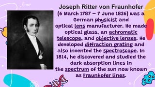
Joseph Ritter vonFraunhofer
(6 March 1787 – 7 June 1826) was a
German physicist and
optical lens manufacturer. He made
optical glass, an achromatic
telescope, and objective lenses. He
developed diffraction grating and
also invented the spectroscope. In
1814, he discovered and studied the
dark absorption lines in
the spectrum of the sun now known
as Fraunhofer lines.
7.
FRAUNHOFER DIFFRACTION
Equation isused to model the
diffraction of waves when the
diffraction pattern is viewed at a
long distance from the diffracting
object, and also when it is viewed at
the focal plane of an imaging lens.
REFERENCES
Johnisaac. (2020, January18). Diffraction-Fraunhofer Diffraction [Slide
show]. SlideShare.
https://www.slideshare.net/slideshow/diffractionfraunhofer-diffraction
/221205244
Wikipedia contributors. (2024, August 20). Joseph von Fraunhofer.
Wikipedia. https://en.m.wikipedia.org/wiki/Joseph_von_Fraunhofer
Wikipedia contributors. (2024b, September 13). Augustin-Jean Fresnel.
Wikipedia. https://en.m.wikipedia.org/wiki/Augustin-Jean_Fresnel
What is Fraunhofer and Fresnel Diffraction? - GoPhotonics.com. (n.d.).
https://www.gophotonics.com/community/what-is-fraunhofer-and-fres
nel-diffraction
DIFFRACTION FROM ASINGLE SLIT
– occurs when light passes through a
narrow slit, producing a unique interference
pattern characterized by a broad central
maximum with narrower and dimmer
maxima to the sides.
14.
DIFFRACTION PATTERNS
– Isthe brightest region in a single slit
diffraction pattern, appearing at the center of
the screen. It’s formed due to constructive
interference, where light waves traveling
straight through the slit reinforce each other,
resulting in a more intense central peak.
Central Maximum
DIFFRACTION PATTERN
– Theseare the less bright peaks that occur
on either side of the central maximum.
– They appear as smaller peaks with lower
intensity compared to the central
maximum.
Secondary Maxima (Less Bright
Spot)
17.
DIFFRACTION PATTERN
– Theseare the dark regions where destructive
interference occurs.
– In these regions, the waves cancel each other
out, resulting in no light.
– Minima represent the troughs in the
interference pattern.
Minima (Dark
Regions)
18.
MATHEMATICAL DESCRIPTION
Destructive Interferencefor a Single
Slit
WHERE:
d – width of the slit
teta – angle relative to the original direction of the light
m – integer representing the order of the minimum
(except m = 0, which corresponds to the central maximum)
lambda – wavelength of the wave
WHAT IS SINGLESLIT DIFFRACTION?
• Single slit diffraction is a phenomenon that occurs
when light passes through a narrow opening, resulting
in a characteristic pattern of alternating dark and
bright regions on a screen.
• The intensity of these fringes varies, with the central
maximum being the brightest and widest, while
subsequent maxima are narrower and less intense.
22.
BASIC PRINCIPLES:
● Whenlight waves pass through a single slit, they can be
treated as originating from multiple point sources along
the width of the slit. Each point acts as a Huygens source,
emitting wavelets that interfere with one another. The
resultant intensity at any point on the screen depends on
the path difference between these wavelets.
The condition for destructive interference (minima) occurs
when:
Dsinθ=mλ
Characteristics of theDiffraction Pattern
1. Central Maximum: The brightest and widest part of the
pattern.
2. Subsequent Maxima: These are less intense and become
narrower as you move away from the center.
3. Minima: Points where destructive interference occurs,
leading to zero intensity.
The width of the central maximum can be approximated for
small angles as:
OBJECTIVES:
• Students willbe able to know what is a multipl-slits.
• Students will be able to identify the principal
maxima and secondary maxima in a multiple-slit
interference pattern.
28.
MULTIPLE
SLITS
refers to anarrangement
where light (or other waves)
passes through more than one
narrow opening.
29.
KEY TERMS TOREMEMBER
PRINCIPAL
MAXIMA
FORMULA:
SECONDARY
MAXIMA
- noticeably taller and narrower for a greater
number of slits. These are the brightest
fringes in the interference pattern.
- these are much fainter bright fringes
located between the principal maxima. They
are less bright because the waves from the
different slits don't arrive perfectly in phase.
WHERE:
d – width of the slit
teta – angle relative to the original direction of the light
m – integer representing the order of the minimum
(except m = 0, which corresponds to the central maximum)
lambda – wavelength of the wave
DIFFRACTION
- It isdefined as the bending of light around
the corners of an obstacle or through an
aperture into the region of geometrical
shadow of the obstacle/aperture.
34.
A (transmission) diffractiongrating
is an arrangement of identical,
equally spaced parallel lines
ruled on glass.
Diffraction gratings
are used to produce
optical spectra
35.
Each of theclear spaces (A,B,C
etc) acts like a very narrow slit
and produces its own
diffraction.
The light is from the same
monochromatic source and
therefore is coherent.
36.
Consider the lightwhich is diffracted
by each slit at some angle θ to the
normal.
The slits are equally spaced so that if
angle θ produces light that phase
at A and B (and therefore
positively reinforces ) then the
light will also be in phase from
every other slit and also produce
positive reinforcement.
38.
Diffraction Grating
The angleθ will be slightly different for each
wavelength of light and so the grating
separates white light into its spectrum and
does this much more effectively than a
prism.
The light needs to be focussed with the
eyepiece lens of a telescope or
spectrometer ( or the lens of the eye) after it
39.
Diffraction Grating
A diffractiongrating with a large
number of lines produces very
sharp maxima and completely
destructive interference at other
angles
What is X-rayDiffraction?
X-ray was first discovered by W.C. Roentgen by 1895. It is an
electromagnetic wave of high energy and very short wavelength, which is
able to pass through many materials opaque to light.
• X-RAY
• DIFFRACTION
It is the process by which a beam of light or other system of waves is
spread out as a result of passing through a narrow aperture or across an
edge, typically accompanied by interference between the wave forms
produced.
43.
What is X-rayDiffraction?
It is a phenomenon in which atoms of a crystal by virtue of their uniform
spacing, cause an interference pattern of the waves present in an
incident beams of X-rays. The atomic planes of the crystal act on the
X-rays in exactly the same manner as does a uniformly ruled diffraction
grating on a beam of light.
• X-RAY DIFFRACTION
44.
BASICS OF CRYSTALLOGRAPHY
•A crystal consists of a periodic arrangement of the
unit cell into a lattice. The unit cell can contain a
single atom or atoms in a fixed arrangement.
• Crystals consist of planes of atoms that are
spaced a distance d apart, but can be resolved
into many atomic planes, each with a different
d-spacing.
45.
CRYSTAL LATTICES
The crystallattice is the symmetrical three-dimensional structural
arrangements of atoms, ions or molecules (constituent particle) inside
a crystalline solid as points. It can be defined as the geometrical
arrangement of the atoms, ions or molecules of the crystalline solid as
points in space.
46.
Characteristics of aCrystal
Lattice
•In a crystal lattice, each atom, molecule or ions
(constituent particle) is represented by a single point.
•These points are called lattice site or lattice point.
•Lattice sites or points are together joined by a
straight line in a crystal lattice, called lattice planes or
crystal planes.
•When we connect these straight lines we can get a
three-dimensional view of the structure. This 3D
arrangement is called Crystal Lattice also known as
Bravais Lattices.
47.
Bragg’s Law
Bragg’s Lawis a physical law explaining
the relationship between an X-ray light
shooting into and its reflection off a
crystal surface. Introduced by W.H.
Bragg and his son W.L. Bragg.
Bragg's Law Statement
Bragg's Law states that, "When the
X-ray is incident onto a crystal surface,
its angle of incidence, θ, will reflect with
the same angle of scattering, θ"
Bragg’s Equation
n isan Integer
λ is the Wavelength of Incident X-ray
d is the Distance between Crystal Planes
θ is the Angle of Incidence
Equation for Bragg's Law is:
nλ = 2d.sin θ
50.
X-ray Diffraction Techniques
•Wide-angle X-ray scattering (WAXS) is a technique used to determine the structure of
materials with short-range order, such as small particles or non-crystalline substances, by
collecting scattering intensity at wide angles corresponding to interatomic distances.
• Small-Angle X-Ray Scattering (SAXS) is a technique used to obtain information about
the size, shape, and spatial arrangement of nanoparticles in a sample. It is particularly
useful for studying nanocrystals and nanostructured thin films.
• Single-crystal X-ray Diffraction is a non-destructive analytical technique which
provides detailed information about the internal lattice of crystalline substances,
including unit cell dimensions, bond-lengths, bond-angles, and details of site-ordering
• Powder X-ray diffraction, the diffraction pattern is obtained from a powder of the
material, rather than an individual crystal.
Debye-Scherrer refers to a method in materials science where a powder《
specimen is exposed to X-rays, resulting in the formation of Debye-Scherrer
rings on a photographic plate or solid state detector, allowing for the
analysis
.of crystalline structures
51.
1. Materials Research
2.Phase Analysis
3. Microstructural Analysis
4. Non-ambient Studies
5. Thin Film Characterization
6. Industrial Applications
7. Forensic Analysis
8. Geological Studies
APPLICATIONS OF X-RAY
DIFFRACTION
Electromagnetic
Waves and its
Behavior
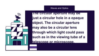
Thecircular aperture may be
just a circular hole in a opaque
object. The circular aperture
may also be a circular lens
through which light could pass
such as in the viewing tube of a
telescope or microscope.
Waves and Optics
Electromagnetic
Waves and its
Behavior
Theability of an optical
instrument or type of film to
separate or distinguish small or
closely adjacent images.
Waves and Optics
61.
Electromagnetic
Waves and its
Behavior
Theresolving power of an objective lens is
measured by its ability to differentiate two
lines or points in an object. The greater the
resolving power, the smaller the minimum
distance between two lines or points that
can still be distinguished. The larger the
N.A., the higher the resolving power.
Waves and Optics
HOLOGRAPHY
> is atechnique that creates
three-dimensional images using light.
> sometimes called lens-less photography,
because it uses the wave characteristics
of light
> HOLOGRAM- 3D outcome
66.
CONSTRUCTIO
N OF THE
HOLOGRAM:
1.Recording: A laser beam is split into two parts: one illuminates the object, and
the other serves as a reference beam.
2. Interference: The light scattered from the object interferes with the reference
beam, creating an interference pattern.
3. Encoding: The interference pattern is recorded on a medium, such as
photographic film or a digital sensor.
4. Reconstruction: When the recorded hologram is illuminated with laser light, the
interference pattern is recreated, and the image of the object appears.
REFERENCES:
OpenStax. (n.d.). 4.8:Holography. In University Physics III - Optics and Modern Physics (OpenStax).
Retrieved from
https://phys.libretexts.org/Bookshelves/University_Physics/University_Physics_(OpenStax)/University_Physi
cs_III_-_Optics_and_Modern_Physics_(OpenStax)/04%3A_Diffraction/4.08%3A_Holography


![REFERENCES
Johnisaac. (2020, January 18). Diffraction-Fraunhofer Diffraction [Slide
show]. SlideShare.
https://www.slideshare.net/slideshow/diffractionfraunhofer-diffraction
/221205244
Wikipedia contributors. (2024, August 20). Joseph von Fraunhofer.
Wikipedia. https://en.m.wikipedia.org/wiki/Joseph_von_Fraunhofer
Wikipedia contributors. (2024b, September 13). Augustin-Jean Fresnel.
Wikipedia. https://en.m.wikipedia.org/wiki/Augustin-Jean_Fresnel
What is Fraunhofer and Fresnel Diffraction? - GoPhotonics.com. (n.d.).
https://www.gophotonics.com/community/what-is-fraunhofer-and-fres
nel-diffraction](https://image.slidesharecdn.com/chaptervii-diffraction-250912134649-482ce6ef/85/CHAPTER-VII-DIFFRACTION-pptx-Waves-and-Optics-11-320.jpg)