309
CHAPTER 18
SOILS ANDFOUNDATIONS
User notes:
About this chapter: Chapter 18 provides criteria for geotechnical and structural considerations in the selection,
design and installation of foundation systems to support the loads imposed by the structure above. This chapter
includes requirements for soils investigation and site preparation for receiving a foundation, including the load-
bearing values for soils and protection for the foundation from frost and water intrusion. Section 1808 addresses
the basic requirements for all foundation types while subsequent sections address foundation requirements that
are specific to shallow foundations and deep foundations.
SECTION 1801
GENERAL
1801.1 Scope. The provisions of this chapter shall apply to building and foundation systems.
SECTION 1802
DESIGN BASIS
1802.1 General. Allowable bearing pressures, allowable stresses and design formulas provided in this
chapter shall be used with the allowable stress design load combinations specified in ASCE 7, Section
2.4 or the alternative allowable stress design load combinations of Section 1605.2. The quality and design
of materials used structurally in excavations and foundations shall comply with the requirements speci-
fied in Chapters 16, 19, 21, 22 and 23. Excavations and fills shall comply with Chapter 33.
SECTION 1803
GEOTECHNICAL INVESTIGATIONS
1803.1 General. Geotechnical investigations shall be conducted in accordance with Section 1803.2 and
reported in accordance with Section 1803.6. Where required by AHJ or where geotechnical investigations
involve in-situ testing, laboratory testing or engineering calculations, such investigations shall be con-
ducted by a registered design professional.
1803.2 Investigations required. Geotechnical investigations shall be conducted in accordance with Sec-
tions 1803.3 through 1803.5.
Exception: AHJ shall be permitted to waive the requirement for a geotechnical investigation where
satisfactory data from adjacent areas is available that demonstrates an investigation is not necessary
for any of the conditions in Sections 1803.5.1 through 1803.5.6 and Sections 1803.5.10 and 1803.5.11.
1803.3 Basis of investigation. Soil classification shall be based on observation and any necessary tests
of the materials disclosed by borings, test pits or other subsurface exploration made in appropriate loca-
tions. Additional studies shall be made as necessary to evaluate slope stability, soil strength, position and
adequacy of load-bearing soils, the effect of moisture variation on soil-bearing capacity, compressibility,
liquefaction and expansiveness.
1803.3.1 Scope of investigation. The scope of the geotechnical investigation including the number
and types of borings or soundings, the equipment used to drill or sample, the in-situ testing equipment
and the laboratory testing program shall be determined by a registered design professional. Number
and location of investigation points shall depend upon the nature of structure to be constructed, ex-
pected variability of stratum in the area. Generalized guidelines, are however specified in Table
1803.3.1.a and Table 1803.3.1.b.
1803.4 Qualified representative. The investigation procedure and apparatus shall be in accordance with
generally accepted engineering practice. The registered design professional shall have a fully qualified
representative (Geotechnical Engineer / Geologist) on site during all boring or sampling operations.
2.
310
TABLE 1803.3.1.a
GENERALIZED GUIDELINESFOR NUMBER OF BORINGS
SR.
NO.
NATURE OF STRUCTURE NUMBER OF INVESTIGA-
TION POINTS
LOCATIONS (TENTA-
TIVE)
1 Compact buildings with footprint
area of less than 40,000 ft2.
5 Four at corners and one at
center
2 Smaller/less important buildings 1-2 At center and/or at critical
load locations
3 Large residential/industrial colonies,
commercial, industrial and infra-
structure projects, etc.
Number and locations to be decided based upon type/im-
portance of structure as well as uniformity of the strata.
An initial estimate of ground variability in the overall area
may be established by performing static or dynamic cone
penetration test at every 100 m in a grid pattern. Number of
investigation points may then be decided based upon varia-
tion in penetration curves.
TABLE 1803.3.1.b
GENERALIZED GUIDELINES FOR DEPTH OF BORINGS
SR.
NO.
PLANNED FOUNDATION TYPE INVESTIGATION DEPTH
1 Isolated spread footings 3-4 times expected foundation width
2 Raft foundation 1-1.5 times foundation width
3 Adjacent foundations with clear spacing less than twice the
width of larger footing
3-4 times foundation length
4 Pile foundations at least 4 times pile diameter below an-
ticipated pile tip
1803.5 Investigated conditions. Geotechnical investigations shall be conducted as indicated in Sections
1803.5.1 through 1803.5.12.
1803.5.1 Classification. Soil materials shall be classified in accordance with ASTM D2487.
1803.5.2 Questionable soil. Where the classification, strength or compressibility of the soil is in doubt
or where a load-bearing value superior to that specified in this code is claimed, AHJ shall be permitted
to require that a geotechnical investigation be conducted.
1803.5.3 Expansive soil. In areas likely to have expansive soil, AHJ shall require soil tests to deter-
mine where such soils do exist.
Soils meeting all four of the following provisions shall be considered to be expansive, except that
tests to show compliance with Items 1, 2 and 3 shall not be required if the test prescribed in Item 4 is
conducted:
1. Plasticity index (PI) of 15 or greater, determined in accordance with ASTM D4318.
2. More than 10 percent of the soil particles pass a No.200 sieve (75 µm), determined in accord-
ance with ASTM D422.
3. More than 10 percent of the soil particles are less than 5 micrometers in size, determined in
accordance with ASTM D422.
4. Expansion index greater than 20, determined in accordance with ASTM D4829.
1803.5.4 Ground-water table. A subsurface soil investigation shall be performed to determine
whether the existing ground-water table is above or within 5 feet (1524 mm) below the elevation of
the lowest floor level where such floor is located below the finished ground level adjacent to the
foundation.
Exception: A subsurface soil investigation to determine the location of the ground-water table shall
not be required where waterproofing is provided in accordance with Section 1805.
3.
311
1803.5.5 Deep foundations.Where deep foundations will be used, a geotechnical investigation shall
be conducted and shall include all of the following, unless sufficient data on which to base the design
and installation is otherwise available:
1. Recommended deep foundation types and installed capacities.
2. Recommended center-to-center spacing of deep foundation elements.
3. Driving criteria.
4. Installation procedures.
5. Field inspection and reporting procedures (to include procedures for verification of the in-
stalled bearing capacity where required).
6. Load test requirements.
7. Suitability of deep foundation materials for the intended environment.
8. Designation of bearing stratum or strata.
9. Reductions for group action, where necessary.
1803.5.6 Rock strata. Where subsurface explorations at the project site indicate variations in the
structure of rock on which foundations are to be constructed, a sufficient number of borings shall be
drilled to sufficient depths to assess the competency of the rock and its load-bearing capacity.
1803.5.7 Excavation near foundations. Where excavation will reduce support from any foundation,
a registered design professional shall prepare an assessment of the structure as determined from ex-
amination of the structure, available design documents, available subsurface data, and, if necessary,
excavation of test pits. The registered design professional shall determine the requirements for sup-
port and protection of any existing foundation and prepare site-specific plans, details and sequence of
work for submission. Such support shall be provided by underpinning, bracing, excavation retention
systems, or by other means acceptable to the AHJ.
1803.5.8 Compacted fill material. Where shallow foundations will bear on compacted fill material
more than 12 inches (305 mm) in depth, a geotechnical investigation shall be conducted and shall
include all of the following:
1. Specifications for the preparation of the site prior to placement of compacted fill material.
2. Specifications for material to be used as compacted fill.
3. Test methods to be used to determine the maximum dry density and optimum moisture content
of the material to be used as compacted fill.
4. Maximum allowable thickness of each lift of compacted fill material.
5. Field test method for determining the in-place dry density of the compacted fill.
6. Minimum acceptable in-place dry density expressed as a percentage of the maximum dry den-
sity determined in accordance with Item 3.
7. Number and frequency of field tests required to determine compliance with Item 6.
1803.5.9 Controlled low-strength material (CLSM). Where shallow foundations will bear on con-
trolled low-strength material (CLSM), a geotechnical investigation shall be conducted and shall in-
clude all of the following:
1. Specifications for the preparation of the site prior to placement of the CLSM.
2. Specifications for the CLSM.
3. Laboratory or field test method(s) to be used to determine the compressive strength or bearing
capacity of the CLSM.
4. Test methods for determining the acceptance of the CLSM in the field.
5. Number and frequency of field tests required to determine compliance with Item 4.
1803.5.10 Alternate setback and clearance. Where setbacks or clearances other than those required
in Section 1808.7 are desired, AHJ shall be permitted to require a geotechnical investigation by a
registered design professional to demonstrate that the intent of Section 1808.7 would be satisfied.
Such an investigation shall include consideration of material, height of slope, slope gradient, load
intensity and erosion characteristics of slope material.
1803.5.11 Seismic Design Categories C through F. For structures assigned to Seismic Design Cat-
egory C, D, E or F, a geotechnical investigation shall be conducted, and shall include an evaluation
of all of the following potential geologic and seismic hazards:
4.
312
1. Slope instability.
2.Liquefaction.
3. Total and differential settlement.
4. Surface displacement due to faulting or seismically induced lateral spreading or lateral flow.
1803.5.12 Seismic Design Categories D through F. For structures assigned to Seismic Design Cat-
egory D, E or F, the geotechnical investigation required by Section 1803.5.11 shall include all of the
following as applicable:
1. The determination of dynamic seismic lateral earth pressures on foundation walls and retaining
walls supporting more than 6 feet (1.83 m) of backfill height due to design earthquake ground
motions.
2. The potential for liquefaction and soil strength loss evaluated for site peak ground acceleration,
earthquake magnitude and source characteristics consistent with the maximum considered
earthquake ground motions. Peak ground acceleration shall be determined based on one of the
following:
2.1. A site-specific study in accordance with Chapter 21 of ASCE 7.
2.2. In accordance with Section 11.8.3 of ASCE 7.
3. An assessment of potential consequences of liquefaction and soil strength loss including, but
not limited to, the following:
3.1. Estimation of total and differential settlement.
3.2. Lateral soil movement.
3.3. Lateral soil loads on foundations.
3.4. Reduction in foundation soil-bearing capacity and lateral soil reaction.
3.5. Soil downdrag and reduction in axial and lateral soil reaction for pile foundations.
3.6. Increases in soil lateral pressures on retaining walls.
3.7. Flotation of buried structures.
4. Discussion of mitigation measures such as, but not limited to, the following:
4.1. Selection of appropriate foundation type and depths.
4.2. Selection of appropriate structural systems to accommodate anticipated displacements
and forces.
4.3. Ground stabilization.
4.4. Any combination of these measures and how they shall be considered in the design of
the structure.
1803.5.13 Site Specific Ground Motion Response Analysis. A site specific ground motion response
analysis shall be performed in the following situations:
1. The facility is identified as critical or essential;
2. A more accurate assessment of hazard level is desired;
3. If the site is located within 6 miles of a known active fault capable of producing a magnitude 5
or greater earthquake and near fault effects are not adequately modeled in the development of
ground motion maps used;
4. Sites where geologic conditions are likely to result in un-conservative spectral acceleration val-
ues if the generalized code response spectra is used (e.g., within the upper 100 ft. a sharp
change in impedance between subsurface strata is present, etc.); or
5. There may be other reasons why the general procedure cannot be used, such as the situation
where the spectral acceleration coefficient at 1.0 second is greater than the spectral acceleration
coefficient at 0.2 second. In such cases, a site specific ground motion analysis should be con-
ducted;
6. Information about one or more active seismic sources for the site has become available since the
information available in the Code and new seismic source information may result in a signifi-
cant change of the seismic hazard at the site.
If a site specific ground motion response analysis is conducted, field measurements of the shear wave
velocity (V) should be obtained through down hole testing as per ASTM D7400-8.
5.
313
If a sitespecific probabilistic seismic hazard analysis (PSHA) is conducted, it shall be conducted in a
manner to generate a uniform-hazard acceleration response spectrum considering a 7 percent probability
of exceedance in 75 years for spectral values over the entire period range of interest. This analysis shall
follow the same basic approach as used by the USGS in developing seismic hazards maps. In this ap-
proach it is necessary to establish the following:
1. The contributing seismic sources;
2. A magnitude fault-rupture-length or source area relation for each contributing fault or source
area to estimate an upper-bound earthquake magnitude for each source zone;
3. Median ground motion attenuation equations for acceleration response spectral values and their
associated standard deviations;
4. A magnitude-recurrence relation for each source zone; and
5. Weighting factors, with justification, for all branches of logic trees used to establish ground
shaking hazards.
In regions of known active faults, site-specific ground motion hazard levels should be based on a deter-
ministic seismic hazard analysis (DSHA), provided that deterministic spectrum is no less than two-thirds
of the probabilistic spectrum, (see AASHTO Article 3.10.2.2). This requires that:
1. The ground motion hazard at a particular site is largely from known faults (e.g., “random” seis-
micity is not a significant contributor to the hazard), and
2. The recurrence interval for large earthquakes on the known faults are generally less than the return
period corresponding to the specified seismic hazard level (e.g., the earthquake recurrence interval
is less than a return period of 1,000 years that corresponds to a seismic hazard level of 7 percent
probability of exceedance in 75 years).
The goal of the site characterization for seismic design is to develop the subsurface profile and soil prop-
erty information needed for seismic analyses. Soil parameters generally required for seismic design in-
clude:
1. Dynamic shear modulus at small strains or shear wave velocity (ASTM D7400-8);
Shear modulus and material damping characteristics as a function of shear strain; (ASTM D 4015
Standard Test Methods for Modulus and Damping of Soils by Fixed-Base Resonant Column
Devices);
2. Cyclic and post-cyclic shear strength parameters (peak and residual) (ASTM D 5311-92);
3. Consolidation parameters such as the Compression Index or Percent Volumetric Strain resulting
from pore pressure dissipation after cyclic loading, (ASTM D 5311-92); and
4. Liquefaction resistance parameters. (ASTM D 5311. Standard test method for load controlled
cyclic triaxial strength of soil).
1803.5.13.1 Peer review. Site specific hazard analysis shall be approved by AHJ with the help of inde-
pendent experts (registered design professionals) in site specific seismic hazard analyses.
1803.6 Reporting. Where geotechnical investigations are required, a written report of the investigations
shall be submitted to the AHJ by the permit applicant at the time of permit application. This geotechnical
report shall include, but need not be limited to, the following information:
1. A plot showing the location of the soil investigations.
2. A complete record of the soil boring and penetration test logs and soil samples.
3. A record of the soil profile.
4. Elevation of the water table, if encountered.
5. Recommendations for foundation type and design criteria, including but not limited to: bearing
capacity of natural or compacted soil; provisions to mitigate the effects of expansive soils; miti-
gation of the effects of liquefaction, differential settlement and varying soil strength; and the
effects of adjacent loads.
6. Expected total and differential settlement.
7. Deep foundation information in accordance with Section 1803.5.5.
8. Special design and construction provisions for foundations of structures founded on expansive
soils, as necessary.
9. Compacted fill material properties and testing in accordance with Section 1803.5.8.
6.
314
10. Controlled low-strengthmaterial properties and testing in accordance with Section 1803.5.9.
SECTION 1804
EXCAVATION, GRADING AND FILL
1804.1 Excavation near foundations. Excavation for any purpose shall not reduce vertical or lateral
support for any foundation or adjacent foundation without first underpinning or protecting the foundation
against detrimental lateral or vertical movement, or both, in accordance with Section 1803.5.7.
1804.2 Underpinning. Where underpinning is chosen to provide the protection or support of adjacent
structures, the underpinning system shall be designed and installed in accordance with provisions of this
chapter and Chapter 33.
1804.2.1 Underpinning sequencing. Underpinning shall be installed in a sequential manner that pro-
tects the neighboring structure and the working construction site. The sequence of installation shall
be identified in the approved construction documents.
1804.3 Placement of backfill. The excavation outside the foundation shall be backfilled with soil that is
free of organic material, construction debris, cobbles and boulders or with a controlled low-strength
material (CLSM). The backfill shall be placed in lifts and compacted in a manner that does not damage
the foundation or the waterproofing or dampproofing material.
Exception: CLSM need not be compacted.
1804.4 Site grading. The ground immediately adjacent to the foundation shall be sloped away from the
building at a slope of not less than 1 unit vertical in 20 units horizontal (5-percent slope) for a minimum
distance of 10 feet (3048 mm) measured perpendicular to the face of the wall. If physical obstructions or
lot lines prohibit 10 feet (3048 mm) of horizontal distance, a 5-percent slope shall be provided to an
approved alternative method of diverting water away from the foundation. Swales used for this purpose
shall be sloped not less than 2 percent where located within 10 feet (3048 mm) of the building foundation.
Impervious surfaces within 10 feet (3048 mm) of the building foundation shall be sloped not less than 2
percent away from the building.
Exceptions:
1. Where climatic or soil conditions warrant, the slope of the ground away from the building
foundation shall be permitted to be reduced to not less than 1 unit vertical in 48 units horizontal
(2-percent slope).
2. Impervious surfaces shall be permitted to be sloped less than 2 percent where the surface is a
door landing or ramp that is required to comply with applicable provisions of means of egress
in the Building Code of Pakistan- Fire Safety Provisions 2016.
The procedure used to establish the final ground level adjacent to the foundation shall account for
additional settlement of the backfill.
1804.5 Grading and fill in flood hazard areas. In flood hazard areas established in Section 1612.3,
grading, fill, or both, shall not be approved:
1. Unless such fill is placed, compacted and sloped to minimize shifting, slumping and erosion dur-
ing the rise and fall of flood water and, as applicable, wave action.
2. In floodways, unless it has been demonstrated through hydrologic and hydraulic analyses per-
formed by a registered design professional in accordance with standard engineering practice that
the proposed grading or fill, or both, will not result in any increase in flood levels during the
occurrence of the design flood.
3. In coastal high hazard areas, unless such fill is conducted or placed to avoid diversion of water
and waves toward any building or structure.
4. Where design flood elevations are specified but floodways have not been designated, unless it has
been demonstrated that the cumulative effect of the proposed flood hazard area encroachment,
when combined with all other existing and anticipated flood hazard area encroachment, will not
increase the design flood elevation more than 1 foot (305 mm) at any point.
1804.6 Compacted fill material. Where shallow foundations will bear on compacted fill material, the
compacted fill shall comply with the provisions of an approved geotechnical report, as set forth in Section
1803.
Exception: Compacted fill material 12 inches (305 mm) in depth or less need not comply with an
approved report, provided that the in-place dry density is not less than 90 percent of the maximum
7.
315
dry density atoptimum moisture content determined in accordance with ASTM D1557. The compac-
tion shall be verified by special inspection in accordance with Section 1705.6.
1804.7 Controlled low-strength material (CLSM). Where shallow foundations will bear on controlled
low-strength material (CLSM), the CLSM shall comply with the provisions of an approved geotechnical
report, as set forth in Section 1803.
SECTION 1805
DAMP PROOFING AND WATERPROOFING
1805.1 General. Walls or portions thereof that retain earth and enclose interior spaces and floors below
grade shall be waterproofed and damp proofed in accordance with this section, with the exception of
those spaces containing groups other than residential and institutional where such omission is not detri-
mental to the building or occupancy.
Ventilation for crawl spaces shall comply with Section 1202.4.
1805.1.1 Story above grade plane. Where a basement is considered a story above grade plane and
the finished ground level adjacent to the basement wall is below the basement floor elevation for 25
percent or more of the perimeter, the floor and walls shall be damp proofed in accordance with Section
1805.2 and a foundation drain shall be installed in accordance with Section 1805.4.2. The foundation
drain shall be installed around the portion of the perimeter where the basement floor is below ground
level. The provisions of Sections 1803.5.4, 1805.3 and 1805.4.1 shall not apply in this case.
1805.1.2 Under-floor space. The finished ground level of an under-floor space such as a crawl space
shall not be located below the bottom of the footings. Where there is evidence that the ground-water
table rises to within 6 inches (152 mm) of the ground level at the outside building perimeter, or that
the surface water does not readily drain from the building site, the ground level of the under-floor
space shall be as high as the outside finished ground level, unless an approved drainage system is
provided. The provisions of Sections 1803.5.4, 1805.2, 1805.3 and 1805.4 shall not apply in this case.
1805.1.2.1 Flood hazard areas. For buildings and structures in flood hazard areas as established
in Section 1612.3, the finished ground level of an under-floor space such as a crawl space shall be
equal to or higher than the outside finished ground level on one side or more.
Exception: Under-floor spaces of Group R-3 buildings that meet the requirements of FEMA
TB 11.
1805.1.3 Ground-water control. Where the ground-water table is lowered and maintained at an ele-
vation not less than 6 inches (152 mm) below the bottom of the lowest floor, the floor and walls shall
be damp proofed in accordance with Section 1805.2. The design of the system to lower the ground-
water table shall be based on accepted principles of engineering that shall consider, but not necessarily
be limited to, permeability of the soil, rate at which water enters the drainage system, rated capacity
of pumps, head against which pumps are to operate and the rated capacity of the disposal area of the
system.
1805.2 Dampproofing. Where hydrostatic pressure will not occur as determined by Section 1803.5.4,
floors and walls for other than wood foundation systems shall be damp proofed in accordance with this
section.
1805.2.1 Floors. Damp proofing materials for floors shall be installed between the floor and the base
course required by Section 1805.4.1, except where a separate floor is provided above a concrete slab.
Where installed beneath the slab, damp proofing shall consist of not less than 6-mil (0.006 inch;
0.152 mm) polyethylene with joints lapped not less than 6 inches (152 mm), or other approved meth-
ods or materials. Where permitted to be installed on top of the slab, damp proofing shall consist of
mopped-on bitumen, not less than 4-mil (0.004 inch; 0.102 mm) polyethylene, or other approved
methods or materials. Joints in the membrane shall be lapped and sealed in accordance with the man-
ufacturer’s installation instructions.
1805.2.2 Walls. Damp proofing materials for walls shall be installed on the exterior surface of the
wall, and shall extend from the top of the footing to above ground level.
Damp proofing shall consist of a bituminous material, 3 pounds per square yard (16 N/m2
) of
acrylic modified cement, 1
/8 inch (3.2 mm) coat of surface-bonding mortar complying with ASTM
C887, any of the materials permitted for waterproofing by Section 1805.3.2 or other approved meth-
ods or materials.
8.
316
1805.2.2.1 Surface preparationof walls. Prior to application of dampproofing materials on con-
crete walls, holes and recesses resulting from the removal of form ties shall be sealed with a bitu-
minous material or other approved methods or materials. Unit masonry walls shall be parged on
the exterior surface below ground level with not less than 3
/8 inch (9.5 mm) of Portland cement
mortar. The parging shall be coved at the footing.
Exception: Parging of unit masonry walls is not required where a material is approved for direct
application to the masonry.
1805.3 Waterproofing. Where the ground-water investigation required by Section 1803.5.4 indicates
that a hydrostatic pressure condition exists, and the design does not include a ground-water control sys-
tem as described in Section 1805.1.3, walls and floors shall be waterproofed in accordance with this
section.
1805.3.1 Floors. Floors required to be waterproofed shall be of concrete and designed and constructed
to withstand the hydrostatic pressures to which the floors will be subjected.
Waterproofing shall be accomplished by placing a membrane of rubberized asphalt, butyl rubber,
fully adhered/fully bonded HDPE or polyolefin composite membrane or not less than 6-mil [0.006
inch (0.152 mm)] polyvinyl chloride with joints lapped not less than 6 inches (152 mm) or other
approved materials under the slab. Joints in the membrane shall be lapped and sealed in accordance
with the manufacturer’s installation instructions.
1805.3.2 Walls. Walls required to be waterproofed shall be of concrete or masonry and shall be de-
signed and constructed to withstand the hydrostatic pressures and other lateral loads to which the
walls will be subjected.
Waterproofing shall be applied from the bottom of the wall to not less than 12 inches (305 mm)
above the maximum elevation of the ground-water table. The remainder of the wall shall be damp
proofed in accordance with Section 1805.2.2. Waterproofing shall consist of two-ply hot-mopped
felts, not less than 6-mil (0.006 inch; 0.152 mm) polyvinyl chloride, 40-mil (0.040 inch; 1.02 mm)
polymer-modified asphalt, 6-mil (0.006 inch; 0.152 mm) polyethylene or other approved methods or
materials capable of bridging nonstructural cracks. Joints in the membrane shall be lapped and sealed
in accordance with the manufacturer’s installation instructions.
1805.3.2.1 Surface preparation of walls. Prior to the application of waterproofing materials on
concrete or masonry walls, the walls shall be prepared in accordance with Section 1805.2.2.1.
1805.3.3 Joints and penetrations. Joints in walls and floors, joints between the wall and floor and
penetrations of the wall and floor shall be made watertight utilizing approved methods and materials.
1805.4 Subsoil drainage system. Where a hydrostatic pressure condition does not exist, damp proofing
shall be provided and a base shall be installed under the floor and a drain installed around the foundation
perimeter. A subsoil drainage system designed and constructed in accordance with Section 1805.1.3 shall
be deemed adequate for lowering the ground-water table.
1805.4.1 Floor base course. Floors of basements, except as provided for in Section 1805.1.1, shall
be placed over a floor base course not less than 4 inches (102 mm) in thickness that consists of gravel
or crushed stone containing not more than 10 percent of material that passes through a No. 4 (4.75
mm) sieve.
Exception: Where a site is located in well-drained gravel or sand/gravel mixture soils, a floor base
course is not required.
1805.4.2 Foundation drain. A drain shall be placed around the perimeter of a foundation that consists
of gravel or crushed stone containing not more than 10-percent material that passes through a No. 4
(4.75 mm) sieve. The drain shall extend not less than 12 inches (305 mm) beyond the outside edge of
the footing. The thickness shall be such that the bottom of the drain is not higher than the bottom of
the base under the floor, and that the top of the drain is not less than 6 inches (152 mm) above the top
of the footing. The top of the drain shall be covered with an approved filter membrane material. Where
a drain tile or perforated pipe is used, the invert of the pipe or tile shall not be higher than the floor
elevation. The top of joints or the top of perforations shall be protected with an approved filter mem-
brane material. The pipe or tile shall be placed on not less than 2 inches (51 mm) of gravel or crushed
stone complying with Section 1805.4.1, and shall be covered with not less than 6 inches (152 mm) of
the same material.
1805.4.3 Drainage discharge. The floor base and foundation perimeter drain shall discharge by grav-
ity or mechanical means into an approved drainage system that complies with the International
Plumbing Code.
9.
317
Exception: Where asite is located in well-drained gravel or sand/gravel mixture soils, a dedicated
drainage system is not required.
SECTION 1806
PRESUMPTIVE LOAD-BEARING VALUES OF SOILS
1806.1 Load combinations. The presumptive load-bearing values provided in Table 1806.2 shall be
used with the allowable stress design load combinations specified in ASCE 7, Section 2.4 or the alterna-
tive allowable stress design load combinations of Section 1605.2. The values of vertical foundation pres-
sure and lateral bearing pressure given in Table 1806.2 shall be permitted to be increased by one-third
where used with the alternative allowable stress design load combinations of Section 1605.2 that include
wind or earthquake loads.
1806.2 Presumptive load-bearing values. The load-bearing values used in design for supporting soils
near the surface shall not exceed the values specified in Table 1806.2 unless data to substantiate the use
of higher values are submitted and approved. Where AHJ has reason to doubt the classification, strength
or compressibility of the soil, the requirements of Section 1803.5.2 shall be satisfied.
Presumptive load-bearing values shall apply to materials with similar physical characteristics and dis-
positions. Mud, organic silt, organic clays, peat or unprepared fill shall not be assumed to have a pre-
sumptive load-bearing capacity unless data to substantiate the use of such a value are submitted.
Exception: A presumptive load-bearing capacity shall be permitted to be used where AHJ deems the
load-bearing capacity of mud, organic silt or unprepared fill is adequate for the support of lightweight
or temporary structures.
1806.3 Lateral load resistance. Where the presumptive values of Table 1806.2 are used to determine
resistance to lateral loads, the calculations shall be in accordance with Sections 1806.3.1 through
1806.3.4.
1806.3.1 Combined resistance. The total resistance to lateral loads shall be permitted to be deter-
mined by combining the values derived from the lateral bearing pressure and the lateral sliding re-
sistance specified in Table 1806.2.
1806.3.2 Lateral sliding resistance limit. For clay, sandy clay, silty clay, clayey silt, silt and sandy
silt, the lateral sliding resistance shall not exceed one-half the dead load.
TABLE 1806.2
PRESUMPTIVE LOAD-BEARING VALUES
CLASS OF MATERIALS
VERTICAL
FOUNDATION PRES-
SURE
(psf)
LATERAL
BEARING PRESSURE
(psf/ft below natural
grade)
LATERAL SLIDING RESISTANCE
Coefficient of frictiona Cohesion (psf)b
1. Crystalline bedrock 12,000 1,200 0.70 —
2. Sedimentary and foliated
rock
4,000 400 0.35 —
3. Sandy gravel and gravel
(GW and GP)
3,000 200 0.35 —
4. Sand, silty sand, clayey sand,
silty gravel and clayey
gravel
(SW, SP, SM, SC, GM and
GC)
2,000 150 0.25 —
5. Clay, sandy clay, silty clay,
clayey silt, silt and sandy
silt
(CL, ML, MH and CH)
1,500 100 — 130
For SI: 1 pound per square foot = 0.0479kPa, 1 pound per square foot per foot = 0.157 kPa/m.
a. Coefficient to be multiplied by the dead load.
b. Cohesion value to be multiplied by the contact area, as limited by Section 1806.3.2.
10.
318
1806.3.3 Increase fordepth. The lateral bearing pressures specified in Table 1806.2 shall be permit-
ted to be increased by the tabular value for each additional foot (305 mm) of depth to a value that is
not greater than 15 times the tabular value.
1806.3.4 Increase for poles. Isolated poles for uses such as flagpoles or signs and poles used to sup-
port buildings that are not adversely affected by a 1
/2-inch (12.7 mm) motion at the ground surface
due to short-term lateral loads shall be permitted to be designed using lateral bearing pressures equal
to two times the tabular values.
SECTION 1807
FOUNDATION WALLS, RETAINING WALLS AND EMBEDDED POSTS AND POLES
1807.1 Foundation walls. Foundation walls shall be designed and constructed in accordance with Sec-
tions 1807.1.1 through 1807.1.6. Foundation walls shall be supported by foundations designed in accord-
ance with Section 1808.
1807.1.1 Design lateral soil loads. Foundation walls shall be designed for the lateral soil loads set
forth in Section 1610.
1807.1.2 Unbalanced backfill height. Unbalanced backfill height is the difference in height between
the exterior finish ground level and the lower of the top of the concrete footing that supports the
foundation wall or the interior finish ground level. Where an interior concrete slab on grade is pro-
vided and is in contact with the interior surface of the foundation wall, the unbalanced backfill height
shall be permitted to be measured from the exterior finish ground level to the top of the interior con-
crete slab.
1807.1.3 Rubble stone foundation walls. Foundation walls of rough or random rubble stone shall be
not less than 16 inches (406 mm) thick. Rubble stone shall not be used for foundation walls of struc-
tures assigned to Seismic Design Category C, D, E or F.
1807.1.4 Permanent wood foundation systems. This section is intentionally left blank.
1807.1.5 Concrete and masonry foundation walls. Concrete and masonry foundation walls shall be
designed in accordance with Chapter 19 or 21, as applicable.
Exception: Concrete and masonry foundation walls shall be permitted to be designed and con-
structed in accordance with Section 1807.1.6.
1807.1.6 Prescriptive design of concrete and masonry foundation walls. Concrete and masonry
foundation walls that are laterally supported at the top and bottom shall be permitted to be designed
and constructed in accordance with this section.
1807.1.6.1 Foundation wall thickness. The thickness of prescriptively designed foundation walls
shall be not less than the thickness of the wall supported, except that foundation walls of not less
than 8-inch (203 mm) nominal width shall be permitted to support brick-veneered frame walls and
10-inch-wide (254 mm) cavity walls provided that the requirements of Section 1807.1.6.2 or
1807.1.6.3 are met.
1807.1.6.2 Concrete foundation walls. Concrete foundation walls shall comply with the follow-
ing:
1. The thickness shall comply with the requirements of Table 1807.1.6.2.
2. The size and spacing of vertical reinforcement shown in Table 1807.1.6.2 are based on the
use of reinforcement with a minimum yield strength of 60,000 pounds per square inch (psi)
(414 MPa). Vertical reinforcement with a minimum yield strength of 40,000 psi (276 MPa)
or 50,000 psi (345 MPa) shall be permitted, provided that the same size bar is used and the
spacing shown in the table is reduced by multiplying the spacing by 0.67 or 0.83, respec-
tively.
3. Vertical reinforcement, where required, shall be placed nearest the inside face of the wall a
distance, d, from the outside face (soil face) of the wall. The distance, d, is equal to the wall
thickness, t, minus 1.25 inches (32 mm) plus one-half the bar diameter, db, [d = t - (1.25 + db /
2)]. The reinforcement shall be placed within a tolerance of ± 3
/8 inch (9.5 mm) where d is less
than or equal to 8 inches (203 mm) or ± 1
/2 inch (12.7 mm) where d is greater than 8 inches
(203 mm).
4. In lieu of the reinforcement shown in Table 1807.1.6.2, smaller reinforcing bar sizes with
closer spacings that provide an equivalent cross-sectional area of reinforcement per unit
length shall be permitted.
11.
319
5. Concrete coverfor reinforcement measured from the inside face of the wall shall be not
less than 3
/4 inch (19.1 mm). Concrete cover for reinforcement measured from the outside
face of the wall shall be not less than 11
/2 inches (38 mm) for No. 5 bars and smaller, and
not less than 2 inches (51 mm) for larger bars.
6. Concrete shall have a specified compressive strength, f , of not less than 2,500 psi (17.2
MPa).
7. The unfactored axial load per linear foot of wall shall not exceed 1.2 t f where t is the
specified wall thickness in inches.
1807.1.6.2.1 Seismic requirements. Based on the seismic design category assigned to the struc-
ture in accordance with Section 1613, concrete foundation walls designed using Table
1807.1.6.2 shall be subject to the following limitations:
1. Seismic Design Categories A and B. Not less than one No. 5 bar shall be provided around
window, door and similar sized openings. The bar shall be anchored to develop fy in tension
at the corners of openings.
2. Seismic Design Categories C, D, E and F. Tables shall not be used except as allowed for
plain concrete members in Section 1905.1.7.
1807.1.6.3 Masonry foundation walls. Masonry foundation walls shall comply with the follow-
ing:
1. The thickness shall comply with the requirements of Table 1807.1.6.3(1) for plain masonry
walls or Table 1807.1.6.3(2), 1807.1.6.3(3) or 1807.1.6.3(4) for masonry walls with rein-
forcement.
2. Vertical reinforcement shall have a minimum yield strength of 60,000 psi (414 MPa).
3. The specified location of the reinforcement shall equal or exceed the effective depth dis-
tance, d, noted in Tables 1807.1.6.3(2), 1807.1.6.3(3) and 1807.1.6.3(4) and shall be meas-
ured from the face of the exterior (soil) side of the wall to the center of the vertical rein-
forcement. The reinforcement shall be placed within the tolerances specified in TMS 602,
Article 3.4.B.11, of the specified location.
4. Grout shall comply with Section 2103.3.
5. Concrete masonry units shall comply with ASTM C90.
6. Clay masonry units shall comply with ASTM C652 for hollow brick, except compliance
with ASTM C62 or ASTM C216 shall be permitted where solid masonry units are installed
in accordance with Table 1807.1.6.3(1) for plain masonry.
7. Masonry units shall be laid in running bond and installed with Type M or S mortar in
accordance with Section 2103.2.1.
TABLE 1807.1.6.2
CONCRETE FOUNDATION WALLSb, c
MAXIMUM
WALL
HEIGHT
(feet)
MAXIMUM UNBAL-
ANCED BACKFILL
HEIGHTe
(feet)
MINIMUM VERTICAL REINFORCEMENT-BAR SIZE AND SPACING (inches)
Design lateral soil loada (psf per foot of depth)
30d 45d 60
Minimum wall thickness (inches)
7.5 9.5 11.5 7.5 9.5 11.5 7.5 9.5 11.5
5
4
5
PC
PC
PC
PC
PC
PC
PC
PC
PC
PC
PC
PC
PC
PC
PC
PC
PC
PC
6
4
5
6
PC
PC
PC
PC
PC
PC
PC
PC
PC
PC
PC
PC
PC
PC
PC
PC
PC
PC
PC
PC
PC
PC
PC
PC
PC
PC
PC
7
4
5
6
7
PC
PC
PC
PC
PC
PC
PC
PC
PC
PC
PC
PC
PC
PC
PC
#5 at
46
PC
PC
PC
PC
PC
PC
PC
PC
PC
PC
#5 at
48
PC
PC
PC
PC
PC
PC
PC
PC
12.
320
#6 at
48
8
4
5
6
7
8
PC
PC
PC
PC
#5 at
47
PC
PC
PC
PC
PC
PC
PC
PC
PC
PC
PC
PC
PC
#5at
41
#6 at
43
PC
PC
PC
PC
PC
PC
PC
PC
PC
PC
PC
PC
#5 at
43
#6 at
43
#6 at
32
PC
PC
PC
PC
#6 at
44
PC
PC
PC
PC
PC
9
4
5
6
7
8
9d
PC
PC
PC
PC
#5 at
41
#6 at
46
PC
PC
PC
PC
PC
PC
PC
PC
PC
PC
PC
PC
PC
PC
PC
#5 at
37
#6 at
38
#7 at
41
PC
PC
PC
PC
#5 at
37
#6 at
41
PC
PC
PC
PC
PC
PC
PC
PC
#5 at
39
#6 at
38
#7 at
39
#7 at
31
PC
PC
PC
#5 at
37
#6 at
39
#7 at
41
PC
PC
PC
PC
#4 at
48
#6 at
39
10
4
5
6
7
8
9d
10d
PC
PC
PC
PC
#5 at
38
#6 at
41
#7 at
45
PC
PC
PC
PC
PC
#4 at
48
#6 at
45
PC
PC
PC
PC
PC
PC
PC
PC
PC
PC
#6 at
48
#7 at
47
#7 at
37
#7 at
31
PC
PC
PC
PC
#6 at
47
#7 at
48
#7 at
40
PC
PC
PC
PC
PC
#4 at
48
#6 at
38
PC
PC
#5 at
37
#6 at
35
#7 at
35
#6 at
22
#6 at
22
PC
PC
PC
#6 at
48
#7 at
47
#7 at
37
#7 at
30
PC
PC
PC
PC
#6 at
45
#7 at
47
#7 at
38
For SI: 1 inch = 25.4 mm, 1 foot = 304.8 mm, 1 pound per square foot per foot = 0.157 kPa/m.
a. For design lateral soil loads, see Section 1610.
b. Provisions for this table are based on design and construction requirements specified in Section 1807.1.6.2.
c. PC = Plain Concrete.
d. Where unbalanced backfill height exceeds 8 feet and design lateral soil loads from Table 1610.1 are used, the requirements for
30 and 45 psf per foot of depth are not applicable (see Section 1610).
e. For height of unbalanced backfill, see Section 1807.1.2.
8. The unfactored axial load per linear foot of wall shall not exceed 1.2 tf where t is the
specified wall thickness in inches and f is the specified compressive strength of masonry
in pounds per square inch.
9. Not less than 4 inches (102 mm) of solid masonry shall be provided at girder supports at
the top of hollow masonry unit foundation walls.
10. Corbeling of masonry shall be in accordance with Section 2104.1. Where an 8-inch (203
mm) wall is corbeled, the top corbel shall not extend higher than the bottom of the floor
framing and shall be a full course of headers not less than 6 inches (152 mm) in length or
the top course bed joint shall be tied to the vertical wall projection. The tie shall be W2.8
(4.8 mm) and spaced at a maximum horizontal distance of 36 inches (914 mm). The hollow
space behind the corbelled masonry shall be filled with mortar or grout.
13.
321
TABLE 1807.1.6.3(1)
PLAIN MASONRYFOUNDATION WALLSa, b, c
MAXIMUM
WALL HEIGHT
(feet)
MAXIMUM UNBAL-
ANCED BACKFILL
HEIGHTe
(feet)
MINIMUM NOMINAL WALL THICKNESS (inches)
Design lateral soil loada (psf per foot of depth)
30f 45f 60
7
4 (or less)
5
6
7
8
8
10
12
8
10
12
10 (solidc)
8
10
10 (solidc)
10 (solidc)
8
4 (or less)
5
6
7
8
8
8
10
12
10 (solidc)
8
10
12
12 (solidc)
12 (solidc)
8
12
12 (solidc)
Note d
Note d
9
4 (or less)
5
6
7
8
9f
8
8
12
12(solidc
)
12(solidc
)
Note d
8
10
12
12 (solidc
)
Note d
Note d
8
12
12 (solidc)
Note d
Note d
Note d
For SI: 1 inch = 25.4 mm, 1 foot = 304.8 mm, 1 pound per square foot per foot = 0.157 kPa/m.
a. For design lateral soil loads, see Section 1610.
b. Provisions for this table are based on design and construction requirements specified in Section 1807.1.6.3.
c. Solid grouted hollow units or solid masonry units.
d. A design in compliance with Chapter 21 or reinforcement in accordance with Table 1807.1.6.3(2) is required.
e. For height of unbalanced backfill, see Section 1807.1.2.
f. Where unbalanced backfill height exceeds 8 feet and design lateral soil loads from Table 1610.1 are used, the requirements for
30 and 45 psf per foot of depth are not applicable (see Section 1610).
TABLE 1807.1.6.3(2)
8-INCH MASONRY FOUNDATION WALLS WITH REINFORCEMENT WHERE d ≥ 5 INCHESa, b, c
MAXIMUM
WALL HEIGHT
(feet-inches)
MAXIMUM UNBAL-
ANCED BACKFILL
HEIGHTd
(feet-inches)
MINIMUM VERTICAL REINFORCEMENT-BAR SIZE AND SPACING
(inches)
Design lateral soil loada (psf per foot of depth)
30e 45e 60
7-4
4-0 (or less)
5-0
6-0
7-4
#4 at 48
#4 at 48
#4 at 48
#5 at 48
#4 at 48
#4 at 48
#5 at 48
#6 at 48
#4 at 48
#4 at 48
#5 at 48
#7 at 48
8-0
4-0 (or less)
5-0
6-0
7-0
8-0
#4 at 48
#4 at 48
#4 at 48
#5 at 48
#5 at 48
#4 at 48
#4 at 48
#5 at 48
#6 at 48
#6 at 48
#4 at 48
#4 at 48
#5 at 48
#7 at 48
#7 at 48
8-8
4-0 (or less)
5-0
6-0
7-0
8-8e
#4 at 48
#4 at 48
#4 at 48
#5 at 48
#6 at 48
#4 at 48
#4 at 48
#5 at 48
#6 at 48
#7 at 48
#4 at 48
#5 at 48
#6 at 48
#7 at 48
#8 at 48
9-4
4-0 (or less)
5-0
6-0
7-0
8-0
9-4e
#4 at 48
#4 at 48
#4 at 48
#5 at 48
#6 at 48
#7 at 48
#4 at 48
#4 at 48
#5 at 48
#6 at 48
#7 at 48
#8 at 48
#4 at 48
#5 at 48
#6 at 48
#7 at 48
#8 at 48
#9 at 48
14.
322
MAXIMUM
WALL HEIGHT
(feet-inches)
MAXIMUM UNBAL-
ANCEDBACKFILL
HEIGHTd
(feet-inches)
MINIMUM VERTICAL REINFORCEMENT-BAR SIZE AND SPACING
(inches)
Design lateral soil loada (psf per foot of depth)
30e 45e 60
10-0
4-0 (or less)
5-0
6-0
7-0
8-0
9-0e
10-10e
#4 at 48
#4 at 48
#4 at 48
#5 at 48
#6 at 48
#7 at 48
#7 at 48
#4 at 48
#4 at 48
#5 at 48
#6 at 48
#7 at 48
#8 at 48
#9 at 48
#4 at 48
#5 at 48
#6 at 48
#7 at 48
#8 at 48
#9 at 48
#9 at 48
For SI: 1 inch = 25.4 mm, 1 foot = 304.8 mm, 1 pound per square foot per foot = 0.157 kPa/m.
a. For design lateral soil loads, see Section 1610.
b. Provisions for this table are based on design and construction requirements specified in Section 1807.1.6.3.
c. For alternative reinforcement, see Section 1807.1.6.3.1.
d. For height of unbalanced backfill, see Section 1807.1.2.
e. Where unbalanced backfill height exceeds 8 feet and design lateral soil loads from Table 1610.1 are used, the requirements for
30 and 45 psf per foot of depth are not applicable. See Section 1610.
TABLE 1807.1.6.3(3)
10-INCH MASONRY FOUNDATION WALLS WITH REINFORCEMENT WHERE d ≥ 6.75 INCHESa, b, c
MAXIMUM
WALL HEIGHT
(feet-inches)
MAXIMUM UNBAL-
ANCED BACKFILL
HEIGHTd
(feet-inches)
MINIMUM VERTICAL REINFORCEMENT-BAR SIZE AND SPACING
(inches)
Design lateral soil loada (psf per foot of depth)
30e 45e 60
7-4
4-0 (or less)
5-0
6-0
7-4
#4 at 56
#4 at 56
#4 at 56
#4 at 56
#4 at 56
#4 at 56
#4 at 56
#5 at 56
#4 at 56
#4 at 56
#5 at 56
#6 at 56
8-0
4-0 (or less)
5-0
6-0
7-0
8-0
#4 at 56
#4 at 56
#4 at 56
#4 at 56
#5 at 56
#4 at 56
#4 at 56
#4 at 56
#5 at 56
#6 at 56
#4 at 56
#4 at 56
#5 at 56
#6 at 56
#7 at 56
8-8
4-0 (or less)
5-0
6-0
7-0
8-8e
#4 at 56
#4 at 56
#4 at 56
#4 at 56
#5 at 56
#4 at 56
#4 at 56
#4 at 56
#5 at 56
#7 at 56
#4 at 56
#4 at 56
#5 at 56
#6 at 56
#8 at 56
9-4
4-0 (or less)
5-0
6-0
7-0
8-0
9-4e
#4 at 56
#4 at 56
#4 at 56
#4 at 56
#5 at 56
#6 at 56
#4 at 56
#4 at 56
#5 at 56
#5 at 56
#6 at 56
#7 at 56
#4 at 56
#4 at 56
#5 at 56
#6 at 56
#7 at 56
#7 at 56
10-0
4-0 (or less)
5-0
6-0
7-0
8-0
9-0e
10-0e
#4 at 56
#4 at 56
#4 at 56
#5 at 56
#5 at 56
#6 at 56
#7 at 56
#4 at 56
#4 at 56
#5 at 56
#6 at 56
#7 at 56
#7 at 56
#8 at 56
#4 at 56
#4 at 56
#5 at 56
#7 at 56
#8 at 56
#9 at 56
#9 at 56
For SI: 1 inch = 25.4 mm, 1 foot = 304.8 mm, 1 pound per square foot per foot = 1.157 kPa/m.
a. For design lateral soil loads, see Section 1610.
b. Provisions for this table are based on design and construction requirements specified in Section 1807.1.6.3.
c. For alternative reinforcement, see Section 1807.1.6.3.1.
d. For height of unbalanced backfill, see Section 1807.1.2.
15.
323
e. Where unbalancedbackfill height exceeds 8 feet and design lateral soil loads from Table 1610.1 are used, the requirements for
30 and 45 psf per foot of depth are not applicable. See Section 1610.
TABLE 1807.1.6.3(4)
12-INCH MASONRY FOUNDATION WALLS WITH REINFORCEMENT WHERE d ≥ 8.75 INCHESa, b, c
MAXIMUM
WALL HEIGHT
(feet-inches)
MAXIMUM UNBAL-
ANCED BACKFILL
HEIGHTd
(feet-inches)
MINIMUM VERTICAL REINFORCEMENT-BAR SIZE AND SPACING
(inches)
Design lateral soil loada (psf per foot of depth)
30e 45e 60
7-4
4 (or less)
5-0
6-0
7-4
#4 at 72
#4 at 72
#4 at 72
#4 at 72
#4 at 72
#4 at 72
#4 at 72
#5 at 72
#4 at 72
#4 at 72
#5 at 72
#6 at 72
8-0
4 (or less)
5-0
6-0
7-0
8-0
#4 at 72
#4 at 72
#4 at 72
#4 at 72
#5 at 72
#4 at 72
#4 at 72
#4 at 72
#5 at 72
#6 at 72
#4 at 72
#4 at 72
#5 at 72
#6 at 72
#8 at 72
8-8
4 (or less)
5-0
6-0
7-0
8-8e
#4 at 72
#4 at 72
#4 at 72
#4 at 72
#5 at 72
#4 at 72
#4 at 72
#4 at 72
#5 at 72
#7 at 72
#4 at 72
#4 at 72
#5 at 72
#6 at 72
#8 at 72
9-4
4 (or less)
5-0
6-0
7-0
8-0
9-4e
#4 at 72
#4 at 72
#4 at 72
#4 at 72
#5 at 72
#6 at 72
#4 at 72
#4 at 72
#5 at 72
#5 at 72
#6 at 72
#7 at 72
#4 at 72
#4 at 72
#5 at 72
#6 at 72
#7 at 72
#8 at 72
10-0
4 (or less)
5-0
6-0
7-0
8-0
9-0e
10-0e
#4 at 72
#4 at 72
#4 at 72
#4 at 72
#5 at 72
#6 at 72
#7 at 72
#4 at 72
#4 at 72
#5 at 72
#6 at 72
#6 at 72
#7 at 72
#8 at 72
#4 at 72
#4 at 72
#5 at 72
#6 at 72
#7 at 72
#8 at 72
#9 at 72
For SI: 1 inch = 25.4 mm, 1 foot = 304.8 mm, 1 pound per square foot per foot = 0.157 kPa/m.
a. For design lateral soil loads, see Section 1610.
b. Provisions for this table are based on design and construction requirements specified in Section 1807.1.6.3.
c. For alternative reinforcement, see Section 1807.1.6.3.1.
d. For height of unbalanced backfill, see Section 1807.1.2.
e. Where unbalanced backfill height exceeds 8 feet and design lateral soil loads from Table 1610.1 are used, the requirements for
30 and 45 psf per foot of depth are not applicable. See Section 1610.
1807.1.6.3.1 Alternative foundation wall reinforcement. In lieu of the reinforcement provisions
for masonry foundation walls in Table 1807.1.6.3(2), 1807.1.6.3(3) or 1807.1.6.3(4), alternative
reinforcing bar sizes and spacings having an equivalent cross-sectional area of reinforcement per
linear foot (mm) of wall shall be permitted to be used, provided that the spacing of reinforcement
does not exceed 72 inches (1829 mm) and reinforcing bar sizes do not exceed No. 11.
1807.1.6.3.2 Seismic requirements. Based on the seismic design category assigned to the struc-
ture in accordance with Section 1613, masonry foundation walls designed using Tables
1807.1.6.3(1) through 1807.1.6.3(4) shall be subject to the following limitations:
1. Seismic Design Categories A and B. No additional seismic requirements.
2. Seismic Design Category C. A design using Tables 1807.1.6.3(1) through
1807.1.6.3(4) is subject to the seismic requirements of Section 7.4.3 of TMS 402.
16.
324
3. Seismic DesignCategory D. A design using Tables 1807.1.6.3(2) through
1807.1.6.3(4) is subject to the seismic requirements of Section 7.4.4 of TMS 402.
4. Seismic Design Categories E and F. A design using Tables 1807.1.6.3(2) through
1807.1.6.3(4) is subject to the seismic requirements of Section 7.4.5 of TMS 402.
1807.2 Retaining walls. Retaining walls shall be designed in accordance with Sections 1807.2.1 through
1807.2.4.
1807.2.1 General. Retaining walls shall be designed to ensure stability against overturning, sliding,
excessive foundation pressure and water uplift.
1807.2.2 Design lateral soil loads. Retaining walls shall be designed for the lateral soil loads set forth
in Section 1610. For structures assigned to Seismic Design Category D, E, or F, the design of retaining
walls supporting more than 6 feet (1829 mm) of backfill height shall incorporate the additional seismic
lateral earth pressure in accordance with the geotechnical investigation where required in Section
1803.2.
1807.2.3 Safety factor. Retaining walls shall be designed to resist the lateral action of soil to produce
sliding and overturning with a minimum safety factor of 1.5 in each case. The load combinations of
Section 1605 shall not apply to this requirement. Instead, design shall be based on 0.7 times nominal
earthquake loads, 1.0 times other nominal loads, and investigation with one or more of the variable
loads set to zero. The safety factor against lateral sliding shall be taken as the available soil resistance
at the base of the retaining wall foundation divided by the net lateral force applied to the retaining
wall.
Exception: Where earthquake loads are included, the minimum safety factor for retaining wall
sliding and overturning shall be 1.1.
1807.2.4 Segmental retaining walls. Dry-cast concrete units used in the construction of segmental
retaining walls shall comply with ASTM C1372.
1807.3 Embedded posts and poles. Designs to resist both axial and lateral loads employing posts or
poles as columns embedded in earth or in concrete footings in earth shall be in accordance with Sections
1807.3.1 through 1807.3.3.
1807.3.1 Limitations. The design procedures outlined in this section are subject to the following
limitations:
1. The frictional resistance for structural walls and slabs on silts and clays shall be limited to one-
half of the normal force imposed on the soil by the weight of the footing or slab.
2. Posts embedded in earth shall not be used to provide lateral support for structural or nonstruc-
tural materials such as plaster, masonry or concrete unless bracing is provided that develops
the limited deflection required.
Wood poles shall be treated in accordance with AWPA U1 for sawn timber posts (Commodity
Specification A, Use Category 4B) and for round timber posts (Commodity Specification B, Use Cat-
egory 4B).
1807.3.2 Design criteria. The depth to resist lateral loads shall be determined using the design criteria
established in Sections 1807.3.2.1 through 1807.3.2.3, or by other methods approved by AHJ.
1807.3.2.1 Nonconstrained. The following formula shall be used in determining the depth of em-
bedment required to resist lateral loads where lateral constraint is not provided at the ground sur-
face, such as by a rigid floor or rigid ground surface pavement, and where lateral constraint is not
provided above the ground surface, such as by a structural diaphragm.
d = 0.5A{1 + [1 + (4.36h/A)]1/2
} (Equation 18-1)
where:
A = 2.34P/(S1b).
b = Diameter of round post or footing or diagonal dimension of square post or footing, feet (m).
d = Depth of embedment in earth in feet (m) but not over 12 feet (3658 mm) for purpose of
computing lateral pressure.
h = Distance in feet (m) from ground surface to point of application of “P.”
P = Applied lateral force in pounds (kN).
S1 = Allowable lateral soil-bearing pressure as set forth in Section 1806.2 based on a depth of
one-third the depth of embedment in pounds per square foot (psf) (kPa).
17.
325
1807.3.2.2 Constrained. Thefollowing formula shall be used to determine the depth of embedment
required to resist lateral loads where lateral constraint is provided at the ground surface, such as by
a rigid floor or pavement.
𝑑 =
.
(Equation 18-2)
or alternatively
𝑑 =
.
(Equation 18-3)
where:
Mg = Moment in the post at grade, in foot-pounds (kN-m).
S3 = Allowable lateral soil-bearing pressure as set forth in Section 1806.2 based on a depth equal
to the depth of embedment in pounds per square foot (kPa).
1807.3.2.3 Vertical load. The resistance to vertical loads shall be determined using the vertical
foundation pressure set forth in Table 1806.2.
1807.3.3 Backfill. The backfill in the annular space around columns not embedded in poured footings
shall be by one of the following methods:
1. Backfill shall be of concrete with a specified compressive strength of not less than 2,000 psi
(13.8 MPa). The hole shall be not less than 4 inches (102 mm) larger than the diameter of the
column at its bottom or 4 inches (102 mm) larger than the diagonal dimension of a square or
rectangular column.
2. Backfill shall be of clean sand. The sand shall be thoroughly compacted by tamping in layers
not more than 8 inches (203 mm) in depth.
3. Backfill shall be of controlled low-strength material (CLSM).
SECTION 1808
FOUNDATIONS
1808.1 General. Foundations shall be designed and constructed in accordance with Sections 1808.2
through 1808.9. Shallow foundations shall satisfy the requirements of Section 1809. Deep foundations
shall satisfy the requirements of Section 1810.
1808.2 Design for capacity and settlement. Foundations shall be so designed that the allowable bearing
capacity of the soil is not exceeded, and that differential settlement is minimized. Foundations in areas
with expansive soils shall be designed in accordance with the provisions of Section 1808.6.
1808.3 Design loads. Foundations shall be designed for the most unfavorable effects due to the combi-
nations of loads specified in Section 2.3 or 2.4 of ASCE 7 or the alternative allowable stress design load
combinations of Section 1605.2. The dead load is permitted to include the weight of foundations and
overlying fill. Reduced live loads, as specified in Sections 1607.12 and 1607.14, shall be permitted to be
used in the design of foundations.
1808.3.1 Seismic overturning. Where foundations are proportioned using the load combinations of
Section 2.3 or 2.4 of ASCE 7 and the computation of seismic overturning effects is by equivalent
lateral force analysis or modal analysis, the proportioning shall be in accordance with Section 12.13.4
of ASCE 7.
1808.3.2 Surcharge. Fill or other surcharge loads shall not be placed adjacent to any building or
structure unless such building or structure is capable of withstanding the additional loads caused by
the fill or the surcharge. Existing footings or foundations that will be affected by any excavation shall
be underpinned or otherwise protected against settlement and shall be protected against detrimental
lateral or vertical movement or both.
Exception: Minor grading for landscaping purposes shall be permitted where done with walk-be-
hind equipment, where the grade is not increased more than 1 foot (305 mm) from original design
grade or where approved by AHJ.
18.
326
1808.4 Vibratory loads.Where machinery operations or other vibrations are transmitted through the
foundation, consideration shall be given in the foundation design to prevent detrimental disturbances of
the soil.
1808.5 Shifting or moving soils. Where it is known that the shallow subsoils are of a shifting or moving
character, foundations shall be carried to a sufficient depth to ensure stability.
1808.6 Design for expansive soils. Foundations for buildings and structures founded on expansive soils
shall be designed in accordance with Section 1808.6.1 or 1808.6.2.
Exceptions: Foundation design need not comply with Section 1808.6.1 or 1808.6.2 where one of the
following conditions is satisfied:
1. The soil is removed in accordance with Section 1808.6.3.
2. AHJ approves stabilization of the soil in accordance with Section 1808.6.4.
1808.6.1 Foundations. Foundations placed on or within the active zone of expansive soils shall be
designed to resist differential volume changes and to prevent structural damage to the supported struc-
ture. Deflection and racking of the supported structure shall be limited to that which will not interfere
with the usability and serviceability of the structure.
Foundations placed below where volume change occurs or below expansive soil shall comply with
the following provisions:
1. Foundations extending into or penetrating expansive soils shall be designed to prevent uplift
of the supported structure.
2. Foundations penetrating expansive soils shall be designed to resist forces exerted on the foun-
dation due to soil volume changes or shall be isolated from the expansive soil.
1808.6.2 Slab-on-ground foundations. Moments, shears and deflections for use in designing slab-
on-ground, mat or raft foundations on expansive soils shall be determined in accordance with
WRI/CRSI Design of Slab-on-Ground Foundations or PTI DC 10.5. Using the moments, shears and
deflections determined above, nonprestressed slabs-on-ground, mat or raft foundations on expansive
soils shall be designed in accordance with WRI/CRSI Design of Slab-on-Ground Foundations and
post-tensioned slab-on-ground, mat or raft foundations on expansive soils shall be designed in accord-
ance with PTI DC 10.5. It shall be permitted to analyze and design such slabs by other methods that
account for soil-structure interaction, the deformed shape of the soil support, the plate or stiffened
plate action of the slab as well as both center lift and edge lift conditions. Such alternative methods
shall be rational and the basis for all aspects and parameters of the method shall be available for peer
review.
1808.6.3 Removal of expansive soil. Where expansive soil is removed in lieu of designing founda-
tions in accordance with Section 1808.6.1 or 1808.6.2, the soil shall be removed to a depth sufficient
to ensure a constant moisture content in the remaining soil. Fill material shall not contain expansive
soils and shall comply with Section 1804.5 or 1804.6.
Exception: Expansive soil need not be removed to the depth of constant moisture, provided that
the confining pressure in the expansive soil created by the fill and supported structure exceeds the
swell pressure.
1808.6.4 Stabilization. Where the active zone of expansive soils is stabilized in lieu of designing
foundations in accordance with Section 1808.6.1 or 1808.6.2, the soil shall be stabilized by chemical,
dewatering, presaturation or equivalent techniques.
1808.7 Foundations on or adjacent to slopes. The placement of buildings and structures on or adjacent
to slopes steeper than one unit vertical in three units horizontal (33.3-percent slope) shall comply with
Sections 1808.7.1 through 1808.7.5.
1808.7.1 Building clearance from ascending slopes. In general, buildings below slopes shall be set
a sufficient distance from the slope to provide protection from slope drainage, erosion and shallow
failures. Except as provided in Section 1808.7.5 and Figure 1808.7.1, the following criteria will be
assumed to provide this protection. Where the existing slope is steeper than one unit vertical in one
unit horizontal (100-percent slope), the toe of the slope shall be assumed to be at the intersection of a
horizontal plane drawn from the top of the foundation and a plane drawn tangent to the slope at an
angle of 45 degrees (0.79 rad) to the horizontal. Where a retaining wall is constructed at the toe of the
slope, the height of the slope shall be measured from the top of the wall to the top of the slope.
1808.7.2 Foundation setback from descending slope surface. Foundations on or adjacent to slope
surfaces shall be founded in firm material with an embedment and set back from the slope surface
19.
327
sufficient to providevertical and lateral support for the foundation without detrimental settlement.
Except as provided for in Section 1808.7.5 and Figure 1808.7.1, the following setback is deemed
adequate to meet the criteria. Where the slope is steeper than 1 unit vertical in 1 unit horizontal (100-
percent slope), the required setback shall be measured from an imaginary plane 45 degrees (0.79 rad)
to the horizontal, projected upward from the toe of the slope.
For SI: 1 foot = 304.8 mm.
FIGURE 1808.7.1
FOUNDATION CLEARANCES FROM SLOPES
1808.7.3 Pools. The setback between pools regulated by this code and slopes shall be equal to one-
half the building footing setback distance required by this section. That portion of the pool wall within
a horizontal distance of 7 feet (2134 mm) from the top of the slope shall be capable of supporting the
water in the pool without soil support.
1808.7.4 Foundation elevation. On graded sites, the top of any exterior foundation shall extend above
the elevation of the street gutter at point of discharge or the inlet of an approved drainage device not
less than 12 inches (305 mm) plus 2 percent. Alternate elevations are permitted subject to the approval
of AHJ, provided that it can be demonstrated that required drainage to the point of discharge and away
from the structure is provided at all locations on the site.
1808.7.5 Alternate setback and clearance. Alternate setbacks and clearances are permitted, subject
to the approval of AHJ. AHJ shall be permitted to require a geotechnical investigation as set forth in
Section 1803.5.10.
1808.8 Concrete foundations. The design, materials and construction of concrete foundations shall
comply with Sections 1808.8.1 through 1808.8.6 and the provisions of Chapter 19.
Exception: Where concrete footings supporting walls of light-frame construction are designed in ac-
cordance with Table 1809.7, a specific design in accordance with Chapter 19 is not required.
1808.8.1 Concrete or grout strength and mix proportioning. Concrete or grout in foundations shall
have a specified compressive strength (f ) not less than the largest applicable value indicated in Table
1808.8.1.
Where concrete or grout is to be pumped, the mix design including slump shall be adjusted to
produce a pumpable mixture.
1808.8.2 Concrete cover. The concrete cover provided for prestressed and nonprestressed reinforce-
ment in foundations shall be not less than the largest applicable value specified in Table 1808.8.2.
Longitudinal bars spaced less than 11
/2 inches (38 mm) clear distance apart shall be considered to be
bundled bars for which the concrete cover provided shall be not less than that required by Section
20.6.1.3.4 of ACI 318. Concrete cover shall be measured from the concrete surface to the outermost
surface of the steel to which the cover requirement applies. Where concrete is placed in a temporary
or permanent casing or a mandrel, the inside face of the casing or mandrel shall be considered to be
the concrete surface.
1808.8.3 Placement of concrete. Concrete shall be placed in such a manner as to ensure the exclusion
of any foreign matter and to secure a full-size foundation. Concrete shall not be placed through water
unless a tremie or other method approved by AHJ is used. Where placed under or in the presence of
water, the concrete shall be deposited by approved means to ensure minimum segregation of the mix
and negligible turbulence of the water. Where depositing concrete from the top of a deep foundation
element, the concrete shall be chuted directly into smooth-sided pipes or tubes or placed in a rapid
and continuous operation through a funnel hopper centered at the top of the element.
20.
328
1808.8.4 Protection ofconcrete. Concrete foundations shall be protected from freezing during de-
positing and for a period of not less than 5 days thereafter. Water shall not be allowed to flow through
the deposited concrete.
TABLE 1808.8.1
MINIMUM SPECIFIED COMPRESSIVE STRENGTH 𝐟𝐜 OF CONCRETE OR GROUT
FOUNDATION ELEMENT OR CONDITION
SPECIFIED COMPRESSIVE
STRENGTH, 𝐟𝐜
1. Foundations for structures assigned to Seismic Design Category A, B or
C
2,500 psi
2a. Foundations for Group R or U occupancies of light-frame construction,
two stories or less in height, assigned to Seismic Design Category D, E
or F
2,500 psi
2b. Foundations for other structures assigned to Seismic Design Category
D, E or F
3,000 psi
3. Precast nonprestressed driven piles 4,000 psi
4. Socketed drilled shafts 4,000 psi
5. Micropiles 4,000 psi
6. Precast prestressed driven piles 5,000 psi
For SI: 1 pound per square inch = 0.00689 MPa.
TABLE 1808.8.2
MINIMUM CONCRETE COVER
FOUNDATION ELEMENT OR CONDITION MINIMUM COVER
1. Shallow foundations
In accordance with Section 20.6 of ACI
318
2. Precast nonprestressed deep foundation elements
Exposed to seawater
Not manufactured under plant conditions
Manufactured under plant control conditions
3 inches
2 inches
In accordance with Section 20.6.1.3.3 of
ACI 318
3. Precast prestressed deep foundation elements
Exposed to seawater
Other
2.5 inches
In accordance with Section 20.6.1.3.3 of
ACI 318
4.Cast-in-place deep foundation elements not enclosed by a steel pipe,
tube or permanent casing
2.5 inches
5. Cast-in-place deep foundation elements enclosed by a steel pipe, tube or
permanent casing
1 inch
6. Structural steel core within a steel pipe, tube or permanent casing 2 inches
7. Cast-in-place drilled shafts enclosed by a stable rock socket 1.5 inches
For SI: 1 inch = 25.4 mm.
1808.8.5 Forming of concrete. Concrete foundations are permitted to be cast against the earth where,
in the opinion of AHJ, soil conditions do not require formwork. Where formwork is required, it shall
be in accordance with Section 26.11 of ACI 318.
1808.8.6 Seismic requirements. See Section 1905 for additional requirements for foundations of
structures assigned to Seismic Design Category C, D, E or F.
For structures assigned to Seismic Design Category D, E or F, provisions of Section 18.13 of ACI 318
shall apply where not in conflict with the provisions of Sections 1808 through 1810.
Exceptions:
1. Detached one- and two-family dwellings of light-frame construction and two stories or less
above grade plane are not required to comply with the provisions of Section 18.13 of ACI 318.
21.
329
2. Section 18.13.4.3(a)of ACI 318 shall not apply.
1808.9 Vertical masonry foundation elements. Vertical masonry foundation elements that are not foun-
dation piers as defined in Section 202 shall be designed as piers, walls or columns, as applicable, in
accordance with TMS 402.
SECTION 1809
SHALLOW FOUNDATIONS
1809.1 General. Shallow foundations shall be designed and constructed in accordance with Sections
1809.2 through 1809.13.
1809.2 Supporting soils. Shallow foundations shall be built on undisturbed soil, compacted fill material
or controlled low-strength material (CLSM). Compacted fill material shall be placed in accordance with
Section 1804.5. CLSM shall be placed in accordance with Section 1804.6.
1809.3 Stepped footings. The top surface of footings shall be level. The bottom surface of footings shall
be permitted to have a slope not exceeding 1 unit vertical in 10 units horizontal (10-percent slope). Foot-
ings shall be stepped where it is necessary to change the elevation of the top surface of the footing or
where the surface of the ground slopes more than 1 unit vertical in 10 units horizontal (10-percent slope).
1809.4 Depth and width of footings. The minimum depth of footings below the undisturbed ground
surface shall be 12 inches (305 mm). Where applicable, the requirements of Section 1809.5 shall be
satisfied. The minimum width of footings shall be 12 inches (305 mm).
1809.5 Frost protection. Except where otherwise protected from frost, foundations and other permanent
supports of buildings and structures shall be protected from frost by one or more of the following meth-
ods:
1. Extending below the frost line of the locality.
2. Constructing in accordance with ASCE 32.
3. Erecting on solid rock.
Exception: Free-standing buildings meeting all of the following conditions shall not be required to
be protected:
1. Assigned to Risk Category I.
2. Area of 600 square feet (56 m2
) or less for light-frame construction or 400 square feet (37 m2
)
or less for other than light-frame construction.
3. Eave height of 10 feet (3048 mm) or less.
Shallow foundations shall not bear on frozen soil unless such frozen condition is of a permanent char-
acter.
1809.5.1 Frost protection at required exits. Frost protection shall be provided at exterior landings
for all required exits with outward-swinging doors. Frost protection shall only be required to the extent
necessary to ensure the unobstructed opening of the required exit doors.
1809.6 Location of footings. Footings on granular soil shall be so located that the line drawn between
the lower edges of adjoining footings shall not have a slope steeper than 30 degrees (0.52 rad) with the
horizontal, unless the material supporting the higher footing is braced or retained or otherwise laterally
supported in an approved manner or a greater slope has been properly established by engineering analy-
sis.
1809.7 Prescriptive footings for light-frame construction. Where a specific design is not provided,
concrete or masonry-unit footings supporting walls of light-frame construction shall be permitted to be
designed in accordance with Table 1809.7.
1809.8 Plain concrete footings. The edge thickness of plain concrete footings supporting walls of other
than light-frame construction shall be not less than 8 inches (203 mm) where placed on soil or rock.
Exception: For plain concrete footings supporting Group R-3 occupancies, the edge thickness is per-
mitted to be 6 inches (152 mm), provided that the footing does not extend beyond a distance greater
than the thickness of the footing on either side of the supported wall.
1809.9 Masonry-unit footings. The design, materials and construction of masonry-unit footings shall
comply with Sections 1809.9.1 and 1809.9.2, and the provisions of Chapter 21.
Exception: Where a specific design is not provided, masonry-unit footings supporting walls of light-
frame construction shall be permitted to be designed in accordance with Table 1809.7.
22.
330
1809.9.1 Dimensions. Masonry-unitfootings shall be laid in Type M or S mortar complying with
Section 2103.2.1 and the depth shall be not less than twice the projection beyond the wall, pier or
column. The width shall be not less than 8 inches (203 mm) wider than the wall supported thereon.
1809.9.2 Offsets. The maximum offset of each course in brick foundation walls stepped up from the
footings shall be 11
/2 inches (38 mm) where laid in single courses, and 3 inches (76 mm) where laid
in double courses.
1809.10 Pier and curtain wall foundations. Except in Seismic Design Categories D, E and F, pier and
curtain wall foundations shall be permitted to be used to support light-frame construction not more than
two stories above grade plane, provided that the following requirements are met:
1. All load-bearing walls shall be placed on continuous concrete footings bonded integrally with
the exterior wall footings.
2. The minimum actual thickness of a load-bearing masonry wall shall be not less than 4 inches
(102 mm) nominal or 35
/8 inches (92 mm) actual thickness, and shall be bonded integrally with
piers spaced 6 feet (1829 mm) on center (o.c.).
3. Piers shall be constructed in accordance with Chapter 21 and the following:
3.1. The unsupported height of the masonry piers shall not exceed 10 times their least di-
mension.
3.2. Where structural clay tile or hollow concrete masonry units are used for piers support-
ing beams and girders, the cellular spaces shall be filled solidly with concrete or Type
M or S mortar.
Exception: Unfilled hollow piers shall be permitted where the unsupported height
of the pier is not more than four times its least dimension.
3.3. Hollow piers shall be capped with 4 inches (102 mm) of solid masonry or concrete or
the cavities of the top course shall be filled with concrete or grout.
4. The maximum height of a 4-inch (102 mm) load-bearing masonry foundation wall supporting
wood frame walls and floors shall not be more than 4 feet (1219 mm) in height.
5. The unbalanced fill for 4-inch (102 mm) foundation walls shall not exceed 24 inches (610 mm)
for solid masonry, nor 12 inches (305 mm) for hollow masonry.
1809.11 Steel grillage footings. Grillage footings of structural steel elements shall be separated with
approved steel spacers and be entirely encased in concrete with not less than 6 inches (152 mm) on the
bottom and not less than 4 inches (102 mm) at all other points. The spaces between the shapes shall be
completely filled with concrete or cement grout.
1809.12 Timber footings. This section is intentionally left blank.
1809.13 Footing seismic ties. Where a structure is assigned to Seismic Design Category D, E or F,
individual spread footings founded on soil defined in Chapter 20 of ASCE 7 as Site Class E or F shall be
interconnected by ties. Unless it is demonstrated that equivalent restraint is provided by reinforced con-
crete beams within slabs on grade or reinforced concrete slabs on grade, ties shall be capable of carrying,
in tension or compression, a force equal to the lesser of the product of the larger footing design gravity
load times the seismic coefficient, SDS, divided by 10 and 25 percent of the smaller footing design gravity
load.
SECTION 1810
DEEP FOUNDATIONS
1810.1 General. Deep foundations shall be analyzed, designed, detailed and installed in accordance with
Sections 1810.1 through 1810.4.
1810.1.1 Geotechnical investigation. Deep foundations shall be designed and installed on the basis
of a geotechnical investigation as set forth in Section 1803.
1810.1.2 Use of existing deep foundation elements. Deep foundation elements left in place where a
structure has been demolished shall not be used for the support of new construction unless satisfactory
evidence is submitted to AHJ, which indicates that the elements are sound and meet the requirements
of this code. Such elements shall be load tested or redriven to verify their capacities. The design load
applied to such elements shall be the lowest allowable load as determined by tests or redriving data.
1810.1.3 Deep foundation elements classified as columns. Deep foundation elements standing un-
braced in air, water or fluid soils shall be classified as columns and designed as such in accordance
23.
331
with the provisionsof this code from their top down to the point where adequate lateral support is
provided in accordance with Section 1810.2.1.
Exception: Where the unsupported height to least horizontal dimension of a cast-in-place deep
foundation element does not exceed three, it shall be permitted to design and construct such an
element as a pedestal in accordance with ACI 318.
1810.1.4 Special types of deep foundations. The use of types of deep foundation elements not spe-
cifically mentioned herein is permitted, subject to the approval of AHJ, upon the submission of ac-
ceptable test data, calculations and other information relating to the structural properties and load
capacity of such elements. The allowable stresses for materials shall not in any case exceed the limi-
tations specified herein.
1810.2 Analysis. The analysis of deep foundations for design shall be in accordance with Sections
1810.2.1 through 1810.2.5.
1810.2.1 Lateral support. Any soil other than fluid soil shall be deemed to afford sufficient lateral
support to prevent buckling of deep foundation elements and to permit the design of the elements in
accordance with accepted engineering practice and the applicable provisions of this code.
Where deep foundation elements stand unbraced in air, water or fluid soils, it shall be permitted to
consider them laterally supported at a point 5 feet (1524 mm) into stiff soil or 10 feet (3048 mm) into
soft soil unless otherwise approved by AHJ on the basis of a geotechnical investigation by a registered
design professional.
1810.2.2 Stability. Deep foundation elements shall be braced to provide lateral stability in all direc-
tions. Three or more elements connected by a rigid cap shall be considered to be braced, provided that
the elements are located in radial directions from the centroid of the group not less than 60 degrees (1
rad) apart. A two-element group in a rigid cap shall be considered to be braced along the axis con-
necting the two elements. Methods used to brace deep foundation elements shall be subject to the
approval of AHJ.
Deep foundation elements supporting walls shall be placed alternately in lines spaced not less than
1 foot (305 mm) apart and located symmetrically under the center of gravity of the wall load carried,
unless effective measures are taken to provide for eccentricity and lateral forces, or the foundation
elements are adequately braced to provide for lateral stability.
Exceptions:
1. Isolated cast-in-place deep foundation elements without lateral bracing shall be permitted
where the least horizontal dimension is not less than 2 feet (610 mm), adequate lateral sup-
port in accordance with Section 1810.2.1 is provided for the entire height and the height
does not exceed 12 times the least horizontal dimension.
2. A single row of deep foundation elements without lateral bracing is permitted for one- and
two-family dwellings and lightweight construction not exceeding two stories above grade
plane or 35 feet (10 668 mm) in building height, provided that the centers of the elements
are located within the width of the supported wall.
1810.2.3 Settlement. The settlement of a single deep foundation element or group thereof shall be
estimated based on approved methods of analysis. The predicted settlement shall cause neither harm-
ful distortion of, nor instability in, the structure, nor cause any element to be loaded beyond its capac-
ity.
1810.2.4 Lateral loads. The moments, shears and lateral deflections used for design of deep founda-
tion elements shall be established considering the nonlinear interaction of the shaft and soil, as deter-
mined by a registered design professional. Where the ratio of the depth of embedment of the element
to its least horizontal dimension is less than or equal to six, it shall be permitted to assume the element
is rigid.
1810.2.4.1 Seismic Design Categories D through F. For structures assigned to Seismic Design
Category D, E or F, deep foundation elements on Site Class E or F sites, as determined in Section
1613.2.2, shall be designed and constructed to withstand maximum imposed curvatures from earth-
quake ground motions and structure response. Curvatures shall include free-field soil strains mod-
ified for soil-foundation-structure interaction coupled with foundation element deformations asso-
ciated with earthquake loads imparted to the foundation by the structure.
Exception: Deep foundation elements that satisfy the following additional detailing require-
ments shall be deemed to comply with the curvature capacity requirements of this section.
24.
332
1. Precast prestressedconcrete piles detailed in accordance with Section 1810.3.8.
2. Cast-in-place deep foundation elements with a minimum longitudinal reinforcement
ratio of 0.005 extending the full length of the element and detailed in accordance with
Sections 18.7.5.2, 18.7.5.3 and 18.7.5.4 of ACI 318 as required by Section
1810.3.9.4.2.2.
1810.2.5 Group effects. The analysis shall include group effects on lateral behavior where the center-
to-center spacing of deep foundation elements in the direction of lateral force is less than eight times
the least horizontal dimension of an element. The analysis shall include group effects on axial behav-
ior where the center-to-center spacing of deep foundation elements is less than three times the least
horizontal dimension of an element. Group effects shall be evaluated using a generally accepted
method of analysis; the analysis for uplift of grouped elements with center-to-center spacing less than
three times the least horizontal dimension of an element shall be evaluated in accordance with Section
1810.3.3.1.6.
1810.3 Design and detailing. Deep foundations shall be designed and detailed in accordance with Sec-
tions 1810.3.1 through 1810.3.13.
1810.3.1 Design conditions. Design of deep foundations shall include the design conditions specified
in Sections 1810.3.1.1 through 1810.3.1.6, as applicable.
1810.3.1.1 Design methods for concrete elements. Where concrete deep foundations are laterally
supported in accordance with Section 1810.2.1 for the entire height and applied forces cause bend-
ing moments not greater than those resulting from accidental eccentricities, structural design of the
element using the allowable stress design load combinations specified in ASCE 7, Section 2.4 or
the alternative allowable stress design load combinations of Section 1605.2 and the allowable
stresses specified in this chapter shall be permitted. Otherwise, the structural design of concrete
deep foundation elements shall use the strength load combinations specified in ASCE 7, Section
2.3 and approved strength design methods.
1810.3.1.2 Composite elements. Where a single deep foundation element comprises two or more
sections of different materials or different types spliced together, each section of the composite
assembly shall satisfy the applicable requirements of this code, and the maximum allowable load
in each section shall be limited by the structural capacity of that section.
1810.3.1.3 Mislocation. The foundation or superstructure shall be designed to resist the effects of
the mislocation of any deep foundation element by not less than 3 inches (76 mm). To resist the
effects of mislocation, compressive overload of deep foundation elements to 110 percent of the
allowable design load shall be permitted.
1810.3.1.4 Driven piles. Driven piles shall be designed and manufactured in accordance with ac-
cepted engineering practice to resist all stresses induced by handling, driving and service loads.
1810.3.1.5 Helical piles. Helical piles shall be designed and manufactured in accordance with ac-
cepted engineering practice to resist all stresses induced by installation into the ground and service
loads.
1810.3.1.6 Casings. Temporary and permanent casings shall be of steel and shall be sufficiently
strong to resist collapse and sufficiently watertight to exclude any foreign materials during the
placing of concrete. Where a permanent casing is considered reinforcing steel, the steel shall be
protected under the conditions specified in Section 1810.3.2.5. Horizontal joints in the casing shall
be spliced in accordance with Section 1810.3.6.
1810.3.2 Materials. The materials used in deep foundation elements shall satisfy the requirements of
Sections 1810.3.2.1 through 1810.3.2.8, as applicable.
1810.3.2.1 Concrete. Where concrete is cast in a steel pipe or where an enlarged base is formed
by compacting concrete, the maximum size for coarse aggregate shall be 3
/4 inch (19.1 mm). Con-
crete to be compacted shall have a zero slump.
1810.3.2.1.1 Seismic hooks. For structures assigned to Seismic Design Category C, D, E or F,
the ends of hoops, spirals and ties used in concrete deep foundation elements shall be terminated
with seismic hooks, as defined in ACI 318, and shall be turned into the confined concrete core.
1810.3.2.1.2 ACI 318 Equation (25.7.3.3). Where this chapter requires detailing of concrete
deep foundation elements in accordance with Section 18.7.5.4 of ACI 318, compliance with
Equation (25.7.3.3) of ACI 318 shall not be required.
1810.3.2.2 Prestressing steel. Prestressing steel shall conform to ASTM A416.
25.
333
1810.3.2.3 Steel. Structuralsteel H-piles and structural steel sheet piling shall conform to the ma-
terial requirements in ASTM A6. Steel pipe piles shall conform to the material requirements in
ASTM A252. Fully welded steel piles shall be fabricated from plates that conform to the material
requirements in ASTM A36, ASTM A283, ASTM A572, ASTM A588 or ASTM A690.
1810.3.2.4 Timber. This section is intentionally left blank.
1810.3.2.4.1 Preservative treatment. This section is intentionally left blank.
1810.3.2.5 Protection of materials. Where boring records or site conditions indicate possible del-
eterious action on the materials used in deep foundation elements because of soil constituents,
changing water levels or other factors, the elements shall be adequately protected by materials,
methods or processes approved by AHJ. Protective materials shall be applied to the elements so as
not to be rendered ineffective by installation. The effectiveness of such protective measures for the
particular purpose shall have been thoroughly established by satisfactory service records or other
evidence.
1810.3.2.6 Allowable stresses. The allowable stresses for materials used in deep foundation ele-
ments shall not exceed those specified in Table 1810.3.2.6.
1810.3.2.7 Increased allowable compressive stress for cased mandrell-driven cast-in-place el-
ements. The allowable compressive stress in the concrete shall be permitted to be increased as
specified in Table 1810.3.2.6 for those portions of permanently cased cast-in-place elements that
satisfy all of the following conditions:
1. The design shall not use the casing to resist any portion of the axial load imposed.
2. The casing shall have a sealed tip and be mandrel driven.
3. The thickness of the casing shall be not less than manufacturer’s standard gage No.14
(0.068 inch) (1.75 mm).
4. The casing shall be seamless or provided with seams of strength equal to the basic material
and be of a configuration that will provide confinement to the cast-in-place concrete.
5. The ratio of steel yield strength (Fy) to specified compressive strength (f ) shall be not less
than six.
6. The nominal diameter of the element shall not be greater than 16 inches (406 mm).
1810.3.2.8 Justification of higher allowable stresses. Use of allowable stresses greater than those
specified in Section 1810.3.2.6 shall be permitted where supporting data justifying such higher
stresses is filed with AHJ. Such substantiating data shall include the following:
1. A geotechnical investigation in accordance with Section 1803.
2. Load tests in accordance with Section 1810.3.3.1.2, regardless of the load supported by the
element.
The design and installation of the deep foundation elements shall be under the direct supervision
of a registered design professional knowledgeable in the field of soil mechanics and deep founda-
tions who shall submit a report to AHJ stating that the elements as installed satisfy the design cri-
teria.
1810.3.3 Determination of allowable loads. The allowable axial and lateral loads on deep foundation
elements shall be determined by an approved formula, load tests or method of analysis.
TABLE 1810.3.2.6
ALLOWABLE STRESSES FOR MATERIALS USED IN DEEP FOUNDATION ELEMENTS
MATERIAL TYPE AND CONDITION
MAXIMUM ALLOWABLE
STRESSa
1. Concrete or grout in compressionb
Cast-in-place with a permanent casing in accordance with Section 1810.3.2.7 or
Section 1810.3.5.3.4
Cast-in-place in other permanent casing or rock
Cast-in-place without a permanent casing
Precast nonprestressed
Precast prestressed
0.4fc
′
0.33fc
′
0.3fc
′
0.33fc
′
0.33fc
′
- 0.27 fpc
2. Nonprestressed reinforcement in compression 0.4 fy ≤ 30,000 psi
26.
334
3. Steel incompression
Cores within concrete-filled pipes or tubes
Pipes, tubes or H-piles, where justified in accordance with Section 1810.3.2.8
Pipes or tubes for micropiles
Other pipes, tubes or H-piles
Helical piles
0.5 Fy ≤ 32,000 psi
0.5 Fy≤ 32,000 psi
0.4 Fy ≤ 32,000 psi
0.35 Fy ≤ 24,000 psi
0.6 Fy ≤ 0.5 Fu
4. Nonprestressed reinforcement in tension
Within micropiles
Other conditions
For load combinations that do not include wind or seismic loads
For load combinations that include wind or seismic loads
0.6 fy
0.5 fy ≤ 30,000 psi
0.5 fy ≤ 40,000 psi
5. Steel in tension
Pipes, tubes or H-piles, where justified in accordance with Section 1810.3.2.8
Other pipes, tubes or H-piles
Helical piles
0.5 Fy ≤ 32,000 psi
0.35 Fy ≤ 24,000 psi
0.6 Fy ≤ 0.5 Fu
a. f ′c is the specified compressive strength of the concrete or grout; fpc is the compressive stress on the gross concrete section due
to effective prestress forces only; fy is the specified yield strength of reinforcement; Fy is the specified minimum yield stress of
steel; Fu is the specified minimum tensile stress of structural steel.
b. The stresses specified apply to the gross cross-sectional area of the concrete for precast prestressed piles and to the net cross-
sectional area for all other piles. Where a temporary or permanent casing is used, the inside face of the casing shall be considered
the outer edge of the concrete cross-section.
1810.3.3.1 Allowable axial load. The allowable axial load on a deep foundation element shall be
determined in accordance with Sections 1810.3.3.1.1 through 1810.3.3.1.9.
Exception: Where approved by AHJ, load testing is not required.
1810.3.3.1.1 Driving criteria. The allowable compressive load on any driven deep foundation
element where determined by the application of an approved driving formula shall not exceed
40 tons (356 kN). For allowable loads above 40 tons (356 kN), the wave equation method of
analysis shall be used to estimate driveability for both driving stresses and net displacement per
blow at the ultimate load. Allowable loads shall be verified by load tests in accordance with
Section 1810.3.3.1.2. The formula or wave equation load shall be determined for gravity-drop
or power-actuated hammers and the hammer energy used shall be the maximum consistent with
the size, strength and weight of the driven elements. The use of a follower is permitted only
with the approval of AHJ. The introduction of fresh hammer cushion or pile cushion material
just prior to final penetration is not permitted.
1810.3.3.1.2 Load tests. Where design compressive loads are greater than those determined
using the allowable stresses specified in Section 1810.3.2.6, where the design load for any deep
foundation element is in doubt, or where cast-in-place deep foundation elements have an en-
larged base formed either by compacting concrete or by driving a precast base, control test
elements shall be tested in accordance with ASTM D1143 or ASTM D4945. One element or
more shall be load tested in each area of uniform subsoil conditions. Where required by AHJ,
additional elements shall be load tested where necessary to establish the safe design capacity.
The resulting allowable loads shall not be more than one-half of the ultimate axial load capacity
of the test element as assessed by one of the published methods listed in Section 1810.3.3.1.3
with consideration for the test type, duration and subsoil. The ultimate axial load capacity shall
be determined by a registered design professional with consideration given to tolerable total
and differential settlements at design load in accordance with Section 1810.2.3. In subsequent
installation of the balance of deep foundation elements, all elements shall be deemed to have a
supporting capacity equal to that of the control element where such elements are of the same
type, size and relative length as the test element; are installed using the same or comparable
methods and equipment as the test element; are installed in similar subsoil conditions as the test
element; and, for driven elements, where the rate of penetration (for example, net displacement
per blow) of such elements is equal to or less than that of the test element driven with the same
hammer through a comparable driving distance. Besides aforementioned proof load tests which
are performed for capacity verification of working piles, similar tests may be performed for
design verification purposes on separately casted prototype piles. Testing method for prototype
piles should be in accordance with ASTM D1143 or ASTM D4945 and loaded preferably till
27.
335
pile failure butin no case less than 2.5 times the design load. Prototype piles may be instru-
mented with telltales, strain gauges, load cells, inclinometers, etc. to establish the interaction of
pile with surrounding soil layers.
1810.3.3.1.3 Load test evaluation methods. It shall be permitted to evaluate load tests of deep
foundation elements using any of the following methods:
1. Davisson Offset Limit.
2. Brinch-Hansen 90-percent Criterion.
3. Butler-Hoy Criterion.
4. Other methods approved by AHJ.
1810.3.3.1.4 Allowable shaft resistance. The assumed shaft resistance developed by any un-
cased cast-in-place deep foundation element shall not exceed one-sixth of the bearing value of
the soil material at minimum depth as set forth in Table 1806.2, up to 500 psf (24 kPa), unless
a greater value is allowed by AHJ on the basis of a geotechnical investigation as specified in
Section 1803 or a greater value is substantiated by a load test in accordance with Section
1810.3.3.1.2. Shaft resistance and end-bearing resistance shall not be assumed to act simultane-
ously unless determined by a geotechnical investigation in accordance with Section 1803.
1810.3.3.1.5 Uplift capacity of a single deep foundation element. Where required by the de-
sign, the uplift capacity of a single deep foundation element shall be determined by an approved
method of analysis based on a minimum factor of safety of three or by load tests conducted in
accordance with ASTM D3689. The maximum allowable uplift load shall not exceed the ulti-
mate load capacity as determined in Section 1810.3.3.1.2, using the results of load tests con-
ducted in accordance with ASTM D3689, divided by a factor of safety of two.
Exception: Where uplift is due to wind or seismic loading, the minimum factor of safety shall
be two where capacity is determined by an analysis and one and one-half where capacity is
determined by load tests.
1810.3.3.1.6 Allowable uplift load of grouped deep foundation elements. For grouped deep
foundation elements subjected to uplift, the allowable uplift load for the group shall be calcu-
lated by a generally accepted method of analysis. Where the deep foundation elements in the
group are placed at a center-to-center spacing less than three times the least horizontal dimen-
sion of the largest single element, the allowable uplift load for the group is permitted to be
calculated as the lesser of:
1. The proposed individual allowable uplift load times the number of elements in the
group.
2. Two-thirds of the effective weight of the group and the soil contained within a block
defined by the perimeter of the group and the length of the element, plus two-thirds of
the ultimate shear resistance along the soil block.
1810.3.3.1.7 Load-bearing capacity. Deep foundation elements shall develop ultimate load
capacities of not less than twice the design working loads in the designated load-bearing layers.
Analysis shall show that soil layers underlying the designated load-bearing layers do not cause
the load-bearing capacity safety factor to be less than two. Load tests on instrumented prototype
piles may be performed as per 1810.3.3.1.2 to establish mobilized soil reaction in the designated
load-bearing layers.
1810.3.3.1.8 Bent deep foundation elements. The load-bearing capacity of deep foundation
elements discovered to have a sharp or sweeping bend shall be determined by an approved
method of analysis or by load testing a representative element.
1810.3.3.1.9 Helical piles. The allowable axial design load, Pa, of helical piles shall be deter-
mined as follows:
Pa = 0.5 Pu (Equation 18-4)
where Pu is the least value of:
1. Base capacity plus shaft resistance of the helical pile. The base capacity is equal to the
sum of the areas of the helical bearing plates times the ultimate bearing capacity of the
soil or rock comprising the bearing stratum. The shaft resistance is equal to the area of
the shaft above the uppermost helical bearing plate times the ultimate skin resistance.
28.
336
2. Ultimate capacitydetermined from well-documented correlations with installation
torque.
3. Ultimate capacity determined from load tests where required by Section 1810.3.3.1.2.
4. Ultimate axial capacity of pile shaft.
5. Ultimate axial capacity of pile shaft couplings.
6. Sum of the ultimate axial capacity of helical bearing plates affixed to pile.
1810.3.3.2 Allowable lateral load. Where required by the design, the lateral load capacity of a
single deep foundation element or a group thereof shall be determined by an approved method of
analysis or by lateral load tests to not less than twice the proposed design working load. The result-
ing allowable load shall not be more than one-half of the load that produces a gross lateral move-
ment of 1 inch (25 mm) at the lower of the top of foundation element and the ground surface, unless
it can be shown that the predicted lateral movement shall cause neither harmful distortion of, nor
instability in, the structure, nor cause any element to be loaded beyond its capacity.
1810.3.4 Subsiding soils or strata. Where deep foundation elements are installed through subsiding
soils or other subsiding strata and derive support from underlying firmer materials, consideration shall
be given to the downward frictional forces potentially imposed on the elements by the subsiding upper
strata.
Where the influence of subsiding soils or strata is considered as imposing loads on the element, the
allowable stresses specified in this chapter shall be permitted to be increased where satisfactory sub-
stantiating data are submitted.
1810.3.5 Dimensions of deep foundation elements. The dimensions of deep foundation elements
shall be in accordance with Sections 1810.3.5.1 through 1810.3.5.3, as applicable.
1810.3.5.1 Precast. The minimum lateral dimension of precast concrete deep foundation elements
shall be 8 inches (203 mm). Corners of square elements shall be chamfered.
1810.3.5.2 Cast-in-place or grouted-in-place. Cast-in-place and grouted-in-place deep founda-
tion elements shall satisfy the requirements of this section.
1810.3.5.2.1 Cased. Cast-in-place or grouted-in-place deep foundation elements with a perma-
nent casing shall have a nominal outside diameter of not less than 8 inches (203 mm).
1810.3.5.2.2 Uncased. Cast-in-place or grouted-in-place deep foundation elements without a
permanent casing shall have a specified diameter of not less than 12 inches (305 mm). The
element length shall not exceed 30 times the specified diameter.
Exception: The length of the element is permitted to exceed 30 times the specified diameter,
provided that the design and installation of the deep foundations are under the direct super-
vision of a registered design professional knowledgeable in the field of soil mechanics and
deep foundations. The registered design professional shall submit a report to AHJ stating
that the elements were installed in compliance with the approved construction documents.
1810.3.5.2.3 Micropiles. Micropiles shall have a nominal diameter of 12 inches (305 mm) or
less. The minimum diameter set forth elsewhere in Section 1810.3.5 shall not apply to micro-
piles.
1810.3.5.3 Steel. Steel deep foundation elements shall satisfy the requirements of this section.
1810.3.5.3.1 Structural steel H-piles. Sections of structural steel H-piles shall comply with the
requirements for HP shapes in ASTM A6, or the following:
1. The flange projections shall not exceed 14 times the minimum thickness of metal in
either the flange or the web and the flange widths shall be not less than 80 percent of
the depth of the section.
2. The nominal depth in the direction of the web shall be not less than 8 inches (203 mm).
3. Flanges and web shall have a minimum nominal thickness of 3
/8 inch (9.5 mm).
For structures assigned to Seismic Design Category D, E or F, design and detailing of H-
piles shall also conform to the requirements of AISC 341.
1810.3.5.3.2 Fully welded steel piles fabricated from plates. Sections of fully welded steel
piles fabricated from plates shall comply with the following:
29.
337
1. The flangeprojections shall not exceed 14 times the minimum thickness of metal in
either the flange or the web and the flange widths shall be not less than 80 percent of
the depth of the section.
2. The nominal depth in the direction of the web shall be not less than 8 inches (203 mm).
3. Flanges and web shall have a minimum nominal thickness of 3
/8 inch (9.5 mm).
1810.3.5.3.3 Structural steel sheet piling. Individual sections of structural steel sheet piling
shall conform to the profile indicated by the manufacturer, and shall conform to the general
requirements specified by ASTM A6.
1810.3.5.3.4 Steel pipes and tubes. Steel pipes and tubes used as deep foundation elements
shall have a nominal outside diameter of not less than 8 inches (203 mm). Where steel pipes or
tubes are driven open ended, they shall have not less than 0.34 square inch (219 mm2
) of steel
in cross section to resist each 1,000 foot-pounds (1356 Nm) of pile hammer energy, or shall
have the equivalent strength for steels having a yield strength greater than 35,000 psi (241 MPa)
or the wave equation analysis shall be permitted to be used to assess compression stresses in-
duced by driving to evaluate if the pile section is appropriate for the selected hammer. Where a
pipe or tube with wall thickness less than 0.179 inch (4.6 mm) is driven open ended, a suitable
cutting shoe shall be provided. Concrete-filled steel pipes or tubes in structures assigned to
Seismic Design Category C, D, E or F shall have a wall thickness of not less than 3
/16 inch (5
mm). The pipe or tube casing for socketed drilled shafts shall have a nominal outside diameter
of not less than 18 inches (457 mm), a wall thickness of not less than 3
/8 inch (9.5 mm) and a
suitable steel driving shoe welded to the bottom; the diameter of the rock socket shall be ap-
proximately equal to the inside diameter of the casing.
Exceptions:
1. There is no minimum diameter for steel pipes or tubes used in micropiles.
2. For mandrel-driven pipes or tubes, the minimum wall thickness shall be 1
/10 inch (2.5
mm).
1810.3.5.3.5 Helical piles. Dimensions of the central shaft and the number, size and thickness
of helical bearing plates shall be sufficient to support the design loads.
1810.3.6 Splices. Splices shall be constructed so as to provide and maintain true alignment and posi-
tion of the component parts of the deep foundation element during installation and subsequent thereto
and shall be designed to resist the axial and shear forces and moments occurring at the location of the
splice during driving and for design load combinations. Where deep foundation elements of the same
type are being spliced, splices shall develop not less than 50 percent of the bending strength of the
weaker section. Where deep foundation elements of different materials or different types are being
spliced, splices shall develop the full compressive strength and not less than 50 percent of the tension
and bending strength of the weaker section. Where structural steel cores are to be spliced, the ends
shall be milled or ground to provide full contact and shall be full-depth welded.
Exception: For buildings assigned to Seismic Design Category A or B, splices need not comply
with the 50-percent tension and bending strength requirements where justified by supporting data.
Splices occurring in the upper 10 feet (3048 mm) of the embedded portion of an element shall be
designed to resist at allowable stresses the moment and shear that would result from an assumed ec-
centricity of the axial load of 3 inches (76 mm), or the element shall be braced in accordance with
Section 1810.2.2 to other deep foundation elements that do not have splices in the upper 10 feet (3048
mm) of embedment.
1810.3.6.1 Seismic Design Categories C through F. For structures assigned to Seismic Design
Category C, D, E or F splices of deep foundation elements shall develop the lesser of the following:
1. The nominal strength of the deep foundation element.
2. The axial and shear forces and moments from the seismic load effects including over-
strength factor in accordance with Section 2.3.6 or 2.4.5 of ASCE 7.
1810.3.7 Top of element detailing at cutoffs. Where a minimum length for reinforcement or the
extent of closely spaced confinement reinforcement is specified at the top of a deep foundation ele-
ment, provisions shall be made so that those specified lengths or extents are maintained after cutoff.
1810.3.8 Precast concrete piles. Precast concrete piles shall be designed and detailed in accordance
with ACI 318.
Exceptions:
30.
338
1. For precastprestressed piles in Seismic Design Category C, the minimum volumetric ratio
of spirals or circular hoops required by Section 18.13.5.10.4 of ACI 318 shall not apply in
cases where the design includes full consideration of load combinations specified in ASCE
7, Section 2.3.6 or Section 2.4.5 and the applicable overstrength factor, Ω0. In such cases,
minimum transverse reinforcement index shall be as specified in Section 13.4.5.6 of ACI
318.
2. For precast prestressed piles in Seismic Design Categories D through F, the minimum vol-
umetric ratio of spirals or circular hoops required by Section 18.13.5.10.5(c) of ACI 318
shall not apply in cases where the design includes full consideration of load combinations
specified in ASCE 7, Section 2.3.6 or Section 2.4.5 and the applicable overstrength factor,
Ω0. In such cases, minimum transverse reinforcement shall be as specified in Section
13.4.5.6 of ACI 318.
1810.3.9 Cast-in-place deep foundations. Cast-in-place deep foundation elements shall be designed
and detailed in accordance with Sections 1810.3.9.1 through 1810.3.9.6. For the construction of cast-
in-place deep foundations, any acceptable drilling method efficient in avoiding significant disturbance
in surrounding soils may be employed. If required, holes may be stabilized using fresh water, admix-
ture or polymer based slurries; in such cases, appropriate measures should be exercised to avoid re-
duction in pile capacities. Before concreting, bottom cleaning of borehole should be ensured through
air lifting, reverse-circulation or any suitable technique with maximum thickness of sedimentation not
greater than 1.5 inch. Pile construction (completion of borehole drilling to end of concreting) should
preferably be completed within 4 hours. Construction of prototype and working piles should follow
the same execution methodology and QA/QC protocols.
1810.3.9.1 Design cracking moment. The design cracking moment (Mn) for a cast-in-place deep
foundation element not enclosed by a structural steel pipe or tube shall be determined using the
following equation:
𝜙𝑀 = 3 𝑓 𝑆 (Equation 18-5)
For SI: 𝜙𝑀 = 0.25 𝑓 𝑆
where:
f = Specified compressive strength of concrete or grout, psi (MPa).
Sm = Elastic section modulus, neglecting reinforcement and casing, cubic inches (mm3
).
1810.3.9.2 Required reinforcement. Where subject to uplift or where the required moment
strength determined using the load combinations of ASCE 7, Section 2.3 exceeds the design crack-
ing moment determined in accordance with Section 1810.3.9.1, cast-in-place deep foundations not
enclosed by a structural steel pipe or tube shall be reinforced.
1810.3.9.3 Placement of reinforcement. Reinforcement where required shall be assembled and
tied together and shall be placed in the deep foundation element as a unit before the reinforced
portion of the element is filled with concrete.
Exceptions:
1. Steel dowels embedded 5 feet (1524 mm) or less shall be permitted to be placed after
concreting, while the concrete is still in a semifluid state.
2. For deep foundation elements installed with a hollow-stem auger, tied reinforcement
shall be placed after elements are concreted, while the concrete is still in a semifluid
state. Longitudinal reinforcement without lateral ties shall be placed either through the
hollow stem of the auger prior to concreting or after concreting, while the concrete is
still in a semifluid state.
3. For Group R-3 and U occupancies not exceeding two stories of light-frame construc-
tion, reinforcement is permitted to be placed after concreting, while the concrete is still
in a semifluid state, and the concrete cover requirement is permitted to be reduced to
2 inches (51 mm), provided that the construction method can be demonstrated to the
satisfaction of AHJ.
1810.3.9.4 Seismic reinforcement. Where a structure is assigned to Seismic Design Category C,
reinforcement shall be provided in accordance with Section 1810.3.9.4.1. Where a structure is as-
signed to Seismic Design Category D, E or F, reinforcement shall be provided in accordance with
Section 1810.3.9.4.2.
•
31.
339
Exceptions:
1. Isolated deepfoundation elements supporting posts of Group R-3 and U occupancies
not exceeding two stories of light-frame construction shall be permitted to be rein-
forced as required by rational analysis but with not less than one No. 4 bar, without
ties or spirals, where detailed so the element is not subject to lateral loads and the soil
provides adequate lateral support in accordance with Section 1810.2.1.
2. Isolated deep foundation elements supporting posts and bracing from decks and patios
appurtenant to Group R-3 and U occupancies not exceeding two stories of light-frame
construction shall be permitted to be reinforced as required by rational analysis but
with not less than one No. 4 bar, without ties or spirals, where the lateral load, E, to
the top of the element does not exceed 200 pounds (890 N) and the soil provides ade-
quate lateral support in accordance with Section 1810.2.1.
3. Deep foundation elements supporting the concrete foundation wall of Group R-3 and
U occupancies not exceeding two stories of light-frame construction shall be permitted
to be reinforced as required by rational analysis but with not less than two No. 4 bars,
without ties or spirals, where the design cracking moment determined in accordance
with Section 1810.3.9.1 exceeds the required moment strength determined using the
load combinations with overstrength factor in Section 2.3.6 or 2.4.5 of ASCE 7 and
the soil provides adequate lateral support in accordance with Section 1810.2.1.
4. Closed ties or spirals where required by Section 1810.3.9.4.2 shall be permitted to be
limited to the top 3 feet (914 mm) of deep foundation elements 10 feet (3048 mm) or
less in depth supporting Group R-3 and U occupancies of Seismic Design Category D,
not exceeding two stories of light-frame construction.
1810.3.9.4.1 Seismic reinforcement in Seismic Design Category C. For structures assigned
to Seismic Design Category C, cast-in-place deep foundation elements shall be reinforced as
specified in this section. Reinforcement shall be provided where required by analysis.
Not fewer than four longitudinal bars, with a minimum longitudinal reinforcement ratio of
0.0025, shall be provided throughout the minimum reinforced length of the element as defined
in this section starting at the top of the element. The minimum reinforced length of the element
shall be taken as the greatest of the following:
1. One-third of the element length.
2. A distance of 10 feet (3048 mm).
3. Three times the least element dimension.
4. The distance from the top of the element to the point where the design cracking mo-
ment determined in accordance with Section 1810.3.9.1 exceeds the required moment
strength determined using the load combinations of ASCE 7, Section 2.3.
Transverse reinforcement shall consist of closed ties or spirals with a minimum 3
/8 inch (9.5
mm) diameter. Spacing of transverse reinforcement shall not exceed the smaller of 6 inches
(152 mm) or 8-longitudinal-bar diameters, within a distance of three times the least element
dimension from the bottom of the pile cap. Spacing of transverse reinforcement shall not exceed
16 longitudinal bar diameters throughout the remainder of the reinforced length.
Exceptions:
1. The requirements of this section shall not apply to concrete cast in structural steel
pipes or tubes.
2. A spiral-welded metal casing of a thickness not less than the manufacturer’s standard
No. 14 gage (0.068 inch) is permitted to provide concrete confinement in lieu of the
closed ties or spirals. Where used as such, the metal casing shall be protected against
possible deleterious action due to soil constituents, changing water levels or other
factors indicated by boring records of site conditions.
1810.3.9.4.2 Seismic reinforcement in Seismic Design Categories D through F. For struc-
tures assigned to Seismic Design Category D, E or F, cast-in-place deep foundation elements
shall be reinforced as specified in this section. Reinforcement shall be provided where required
by analysis.
Not fewer than four longitudinal bars, with a minimum longitudinal reinforcement ratio of
0.005, shall be provided throughout the minimum reinforced length of the element as defined
32.
340
in this sectionstarting at the top of the element. The minimum reinforced length of the element
shall be taken as the greatest of the following:
1. One-half of the element length.
2. A distance of 10 feet (3048 mm).
3. Three times the least element dimension.
4. The distance from the top of the element to the point where the design cracking mo-
ment determined in accordance with Section 1810.3.9.1 exceeds the required moment
strength determined using the load combinations of ASCE 7, Section 2.3.
Transverse reinforcement shall consist of closed ties or spirals not smaller than No. 3 bars
for elements with a least dimension up to 20 inches (508 mm), and No. 4 bars for larger ele-
ments. Throughout the remainder of the reinforced length outside the regions with transverse
confinement reinforcement, as specified in Section 1810.3.9.4.2.1 or 1810.3.9.4.2.2, the spacing
of transverse reinforcement shall not exceed the least of the following:
1. 12 longitudinal bar diameters.
2. One-half the least dimension of the element.
3. 12 inches (305 mm).
Exceptions:
1. The requirements of this section shall not apply to concrete cast in structural steel
pipes or tubes.
2. A spiral-welded metal casing of a thickness not less than manufacturer’s standard No.
14 gage (0.068 inch) is permitted to provide concrete confinement in lieu of the closed
ties or spirals. Where used as such, the metal casing shall be protected against possible
deleterious action due to soil constituents, changing water levels or other factors in-
dicated by boring records of site conditions.
1810.3.9.4.2.1 Site Classes A through D. For Site Class A, B, C or D sites, transverse con-
finement reinforcement shall be provided in the element in accordance with Sections
18.7.5.2, 18.7.5.3 and 18.7.5.4 of ACI 318 within three times the least element dimension of
the bottom of the pile cap. A transverse spiral reinforcement ratio of not less than one-half
of that required in Table 18.10.6.4(g) of ACI 318 shall be permitted.
1810.3.9.4.2.2 Site Classes E and F. For Site Class E or F sites, transverse confinement
reinforcement shall be provided in the element in accordance with Sections 18.7.5.2, 18.7.5.3
and 18.7.5.4 of ACI 318 within seven times the least element dimension of the pile cap and
within seven times the least element dimension of the interfaces of strata that are hard or stiff
and strata that are liquefiable or are composed of soft- to medium-stiff clay.
1810.3.9.5 Belled drilled shafts. Where drilled shafts are belled at the bottom, the edge thickness
of the bell shall be not less than that required for the edge of footings. Where the sides of the bell
slope at an angle less than 60 degrees (1 rad) from the horizontal, the effects of vertical shear shall
be considered.
1810.3.9.6 Socketed drilled shafts. Socketed drilled shafts shall have a permanent pipe or tube
casing that extends down to bedrock and an uncased socket drilled into the bedrock, both filled
with concrete. Socketed drilled shafts shall have reinforcement or a structural steel core for the
length as indicated by an approved method of analysis.
The depth of the rock socket shall be sufficient to develop the full load-bearing capacity of the
element with a minimum safety factor of two, but the depth shall be not less than the outside diam-
eter of the pipe or tube casing. The design of the rock socket is permitted to be predicated on the
sum of the allowable load-bearing pressure on the bottom of the socket plus bond along the sides
of the socket.
Where a structural steel core is used, the gross cross-sectional area of the core shall not exceed
25 percent of the gross area of the drilled shaft.
1810.3.10 Micropiles. Micropiles shall be designed and detailed in accordance with Sections
1810.3.10.1 through 1810.3.10.4.
1810.3.10.1 Construction. Micropiles shall develop their load-carrying capacity by means of a
bond zone in soil, bedrock or a combination of soil and bedrock. Micropiles shall be grouted and
have either a steel pipe or tube or steel reinforcement at every section along the length. It shall be
33.
341
permitted to transitionfrom deformed reinforcing bars to steel pipe or tube reinforcement by ex-
tending the bars into the pipe or tube section by not less than their development length in tension
in accordance with ACI 318.
1810.3.10.2 Materials. Reinforcement shall consist of deformed reinforcing bars in accordance
with ASTM A615 Grade 60 or 75 or ASTM A722 Grade 150.
The steel pipe or tube shall have a minimum wall thickness of 3
/16 inch (4.8 mm). Splices shall
comply with Section 1810.3.6. The steel pipe or tube shall have a minimum yield strength of 45,000
psi (310 MPa) and a minimum elongation of 15 percent as shown by mill certifications or two
coupon test samples per 40,000 pounds (18 160 kg) of pipe or tube.
1810.3.10.3 Reinforcement. For micropiles or portions thereof grouted inside a temporary or per-
manent casing or inside a hole drilled into bedrock or a hole drilled with grout, the steel pipe or
tube or steel reinforcement shall be designed to carry not less than 40 percent of the design com-
pression load. Micropiles or portions thereof grouted in an open hole in soil without temporary or
permanent casing and without suitable means of verifying the hole diameter during grouting shall
be designed to carry the entire compression load in the reinforcing steel. Where a steel pipe or tube
is used for reinforcement, the portion of the grout enclosed within the pipe is permitted to be in-
cluded in the determination of the allowable stress in the grout.
1810.3.10.4 Seismic reinforcement. For structures assigned to Seismic Design Category C, a per-
manent steel casing shall be provided from the top of the micropile down to the point of zero cur-
vature. For structures assigned to Seismic Design Category D, E or F, the micropile shall be con-
sidered as an alternative system in accordance with Section 104.11. The alternative system design,
supporting documentation and test data shall be submitted to AHJ for review and approval.
1810.3.11 Pile caps. Pile caps shall conform with ACI 318 and this section. Pile caps shall be of
reinforced concrete, and shall include all elements to which vertical deep foundation elements are
connected, including grade beams and mats. The soil immediately below the pile cap shall not be
considered as carrying any vertical load, with the exception of a combined pile raft. The tops of ver-
tical deep foundation elements shall be embedded not less than 3 inches (76 mm) into pile caps and
the caps shall extend not less than 4 inches (102 mm) beyond the edges of the elements. The tops of
elements shall be cut or chipped back to sound material before capping.
1810.3.11.1 Seismic Design Categories C through F. For structures assigned to Seismic Design
Category C, D, E or F, concrete deep foundation elements shall be connected to the pile cap in
accordance with ACI 318.
For resistance to uplift forces, anchorage of steel pipes, tubes or H-piles to the pile cap shall be
made by means other than concrete bond to the bare steel section. Concrete-filled steel pipes or
tubes shall have reinforcement of not less than 0.01 times the cross-sectional area of the concrete
fill developed into the cap and extending into the fill a length equal to two times the required cap
embedment, but not less than the development length in tension of the reinforcement.
1810.3.11.2 Seismic Design Categories D through F. For structures assigned to Seismic Design
Category D, E or F, deep foundation element resistance to uplift forces or rotational restraint shall
be provided by anchorage into the pile cap, designed considering the combined effect of axial forces
due to uplift and bending moments due to fixity to the pile cap. Anchorage shall develop not less
than 25 percent of the strength of the element in tension. Anchorage into the pile cap shall comply
with the following:
1. In the case of uplift, the anchorage shall be capable of developing the least of the following:
1.1. The nominal tensile strength of the longitudinal reinforcement in a concrete ele-
ment.
1.2. The nominal tensile strength of a steel element.
1.3. The frictional force developed between the element and the soil multiplied by 1.3.
Exception: The anchorage is permitted to be designed to resist the axial tension force
resulting from the seismic load effects including overstrength factor in accordance with
Section 2.3.6 or 2.4.5 of ASCE 7.
2. In the case of rotational restraint, the anchorage shall be designed to resist the axial and
shear forces, and moments resulting from the seismic load effects including overstrength
factor in accordance with Section 2.3.6 or 2.4.5 of ASCE 7 or the anchorage shall be capa-
ble of developing the full axial, bending and shear nominal strength of the element.
34.
342
3. The connectionbetween the pile cap and the steel H-piles or unfilled steel pipe piles in
structures assigned to Seismic Design Category D, E or F shall be designed for a tensile
force of not less than 10 percent of the pile compression capacity.
Exceptions:
1. Connection tensile capacity need not exceed the strength required to resist
seismic load effects including overstrength of ASCE 7 Section 12.4.3 or
12.14.3.2.
2. Connections need not be provided where the foundation or supported struc-
ture does not rely on the tensile capacity of the piles for stability under the
design seismic force.
Where the vertical lateral-force-resisting elements are columns, the pile cap flexural strengths
shall exceed the column flexural strength. The connection between batter piles and pile caps shall
be designed to resist the nominal strength of the pile acting as a short column. Batter piles and their
connection shall be designed to resist forces and moments that result from the application of seismic
load effects including overstrength factor in accordance with Section 2.3.6 or 2.4.5 of ASCE 7.
1810.3.12 Grade beams. Grade beams shall comply with the provisions of ACI 318.
Exception: Grade beams designed to resist the seismic load effects including overstrength factor
in accordance with Section 2.3.6 or 2.4.5 of ASCE 7.
1810.3.13 Seismic ties. Seismic ties shall comply with the provisions of ACI 318.
Exception: In Group R-3 and U occupancies of light-frame construction, deep foundation elements
supporting foundation walls, isolated interior posts detailed so the element is not subject to lateral
loads or exterior decks and patios are not subject to interconnection where the soils are of adequate
stiffness, subject to the approval of AHJ.
1810.4 Installation. Deep foundations shall be installed in accordance with Section 1810.4. Where a
single deep foundation element comprises two or more sections of different materials or different types
spliced together, each section shall satisfy the applicable conditions of installation.
1810.4.1 Structural integrity. Deep foundation elements shall be installed in such a manner and
sequence as to prevent distortion or damage that would adversely affect the structural integrity of
adjacent structures or of foundation elements being installed or already in place and as to avoid com-
pacting the surrounding soil to the extent that other foundation elements cannot be installed properly.
1810.4.1.1 Compressive strength of precast concrete piles. A precast concrete pile shall not be
driven before the concrete has attained a compressive strength of not less than 75 percent of the
specified compressive strength (f ), but not less than the strength sufficient to withstand handling
and driving forces.
1810.4.1.2 Shafts in unstable soils. Where cast-in-place deep foundation elements are formed
through unstable soils, the open hole shall be stabilized by a casing, slurry, or other approved
method prior to placing the concrete. Where the casing is withdrawn during concreting, the level
of concrete shall be maintained above the bottom of the casing at a sufficient height to offset any
hydrostatic or lateral soil pressure. Driven casings shall be mandrel driven their full length in con-
tact with the surrounding soil.
1810.4.1.3 Driving near uncased concrete. Deep foundation elements shall not be driven within
six element diameters center to center in granular soils or within one-half the element length in
cohesive soils of an uncased element filled with concrete less than 48 hours old unless approved
by AHJ. If driving near uncased concrete elements causes the concrete surface in any completed
element to rise or drop significantly or bleed additional water, the completed element shall be re-
placed.
1810.4.1.4 Driving near cased concrete. Deep foundation elements shall not be driven within four
and one-half average diameters of a cased element filled with concrete less than 24 hours old unless
approved by AHJ. Concrete shall not be placed in casings within heave range of driving.
1810.4.1.5 Defective timber piles. This section in intentionally left blank.
1810.4.2 Identification. Deep foundation materials shall be identified for conformity to the specified
grade with this identity maintained continuously from the point of manufacture to the point of instal-
lation or shall be tested by an approved agency to determine conformity to the specified grade. The
approved agency shall furnish an affidavit of compliance to AHJ.
35.
343
1810.4.3 Location plan.A plan showing the location and designation of deep foundation elements
by an identification system shall be filed with AHJ prior to installation of such elements. Detailed
records for elements shall bear an identification corresponding to that shown on the plan.
1810.4.4 Preexcavation. The use of jetting, augering or other methods of preexcavation shall be sub-
ject to the approval of AHJ. Where permitted, preexcavation shall be carried out in the same manner
as used for deep foundation elements subject to load tests and in such a manner that will not impair
the carrying capacity of the elements already in place or damage adjacent structures. Element tips
shall be advanced below the preexcavated depth until the required resistance or penetration is ob-
tained.
1810.4.5 Vibratory driving. Vibratory drivers shall only be used to install deep foundation elements
where the element load capacity is verified by load tests in accordance with Section 1810.3.3.1.2. The
installation of production elements shall be controlled according to power consumption, rate of pen-
etration or other approved means that ensure element capacities equal or exceed those of the test
elements.
Exceptions:
1. The pile installation is completed by driving with an impact hammer in accordance with
Section 1810.3.3.1.1.
2. The pile is to be used only for lateral resistance.
1810.4.6 Heaved elements. Deep foundation elements that have heaved during the driving of adjacent
elements shall be redriven as necessary to develop the required capacity and penetration, or the ca-
pacity of the element shall be verified by load tests in accordance with Section 1810.3.3.1.2.
1810.4.7 Enlarged base cast-in-place elements. Enlarged bases for cast-in-place deep foundation
elements formed by compacting concrete or by driving a precast base shall be formed in or driven into
granular soils. Such elements shall be constructed in the same manner as successful prototype test
elements driven for the project. Shafts extending through peat or other organic soil shall be encased
in a permanent steel casing. Where a cased shaft is used, the shaft shall be adequately reinforced to
resist column action or the annular space around the shaft shall be filled sufficiently to reestablish
lateral support by the soil. Where heave occurs, the element shall be replaced unless it is demonstrated
that the element is undamaged and capable of carrying twice its design load.
1810.4.8 Hollow-stem augered, cast-in-place elements. Where concrete or grout is placed by pump-
ing through a hollow-stem auger, the auger shall be permitted to rotate in a clockwise direction during
withdrawal. As the auger is withdrawn at a steady rate or in increments not to exceed 1 foot (305 mm),
concreting or grouting pumping pressures shall be measured and maintained high enough at all times
to offset hydrostatic and lateral earth pressures. Concrete or grout volumes shall be measured to ensure
that the volume of concrete or grout placed in each element is equal to or greater than the theoretical
volume of the hole created by the auger. Where the installation process of any element is interrupted
or a loss of concreting or grouting pressure occurs, the element shall be redrilled to 5 feet (1524 mm)
below the elevation of the tip of the auger when the installation was interrupted or concrete or grout
pressure was lost and reformed. Augered cast-in-place elements shall not be installed within six di-
ameters center to center of an element filled with concrete or grout less than 12 hours old, unless
approved by AHJ. If the concrete or grout level in any completed element drops due to installation of
an adjacent element, the element shall be replaced.
1810.4.9 Socketed drilled shafts. The rock socket and pipe or tube casing of socketed drilled shafts
shall be thoroughly cleaned of foreign materials before filling with concrete. Steel cores shall be bed-
ded in cement grout at the base of the rock socket.
1810.4.10 Micropiles. Micropile deep foundation elements shall be permitted to be formed in holes
advanced by rotary or percussive drilling methods, with or without casing. The elements shall be
grouted with a fluid cement grout. The grout shall be pumped through a tremie pipe extending to the
bottom of the element until grout of suitable quality returns at the top of the element. The following
requirements apply to specific installation methods:
1. For micropiles grouted inside a temporary casing, the reinforcing bars shall be inserted prior
to withdrawal of the casing. The casing shall be withdrawn in a controlled manner with the
grout level maintained at the top of the element to ensure that the grout completely fills the
drill hole. During withdrawal of the casing, the grout level inside the casing shall be monitored
to verify that the flow of grout inside the casing is not obstructed.
36.
344
2. For amicropile or portion thereof grouted in an open drill hole in soil without temporary cas-
ing, the minimum design diameter of the drill hole shall be verified by a suitable device during
grouting.
3. For micropiles designed for end bearing, a suitable means shall be employed to verify that the
bearing surface is properly cleaned prior to grouting.
4. Subsequent micropiles shall not be drilled near elements that have been grouted until the grout
has had sufficient time to harden.
5. Micropiles shall be grouted as soon as possible after drilling is completed.
6. For micropiles designed with a full-length casing, the casing shall be pulled back to the top of
the bond zone and reinserted or some other suitable means employed to ensure grout coverage
outside the casing.
1810.4.11 Helical piles. Helical piles shall be installed to specified embedment depth and torsional
resistance criteria as determined by a registered design professional. The torque applied during in-
stallation shall not exceed the manufacturer’s rated maximum installation torque resistance of the
helical pile.
1810.4.12 Special inspection. Special inspections in accordance with Sections 1705.7 and 1705.8
shall be provided for driven and cast-in-place deep foundation elements, respectively. Special inspec-
tions in accordance with Section 1705.9 shall be provided for helical piles


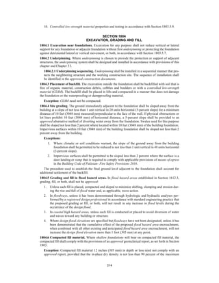

![316
1805.2.2.1 Surface preparation of walls. Prior to application of dampproofing materials on con-
crete walls, holes and recesses resulting from the removal of form ties shall be sealed with a bitu-
minous material or other approved methods or materials. Unit masonry walls shall be parged on
the exterior surface below ground level with not less than 3
/8 inch (9.5 mm) of Portland cement
mortar. The parging shall be coved at the footing.
Exception: Parging of unit masonry walls is not required where a material is approved for direct
application to the masonry.
1805.3 Waterproofing. Where the ground-water investigation required by Section 1803.5.4 indicates
that a hydrostatic pressure condition exists, and the design does not include a ground-water control sys-
tem as described in Section 1805.1.3, walls and floors shall be waterproofed in accordance with this
section.
1805.3.1 Floors. Floors required to be waterproofed shall be of concrete and designed and constructed
to withstand the hydrostatic pressures to which the floors will be subjected.
Waterproofing shall be accomplished by placing a membrane of rubberized asphalt, butyl rubber,
fully adhered/fully bonded HDPE or polyolefin composite membrane or not less than 6-mil [0.006
inch (0.152 mm)] polyvinyl chloride with joints lapped not less than 6 inches (152 mm) or other
approved materials under the slab. Joints in the membrane shall be lapped and sealed in accordance
with the manufacturer’s installation instructions.
1805.3.2 Walls. Walls required to be waterproofed shall be of concrete or masonry and shall be de-
signed and constructed to withstand the hydrostatic pressures and other lateral loads to which the
walls will be subjected.
Waterproofing shall be applied from the bottom of the wall to not less than 12 inches (305 mm)
above the maximum elevation of the ground-water table. The remainder of the wall shall be damp
proofed in accordance with Section 1805.2.2. Waterproofing shall consist of two-ply hot-mopped
felts, not less than 6-mil (0.006 inch; 0.152 mm) polyvinyl chloride, 40-mil (0.040 inch; 1.02 mm)
polymer-modified asphalt, 6-mil (0.006 inch; 0.152 mm) polyethylene or other approved methods or
materials capable of bridging nonstructural cracks. Joints in the membrane shall be lapped and sealed
in accordance with the manufacturer’s installation instructions.
1805.3.2.1 Surface preparation of walls. Prior to the application of waterproofing materials on
concrete or masonry walls, the walls shall be prepared in accordance with Section 1805.2.2.1.
1805.3.3 Joints and penetrations. Joints in walls and floors, joints between the wall and floor and
penetrations of the wall and floor shall be made watertight utilizing approved methods and materials.
1805.4 Subsoil drainage system. Where a hydrostatic pressure condition does not exist, damp proofing
shall be provided and a base shall be installed under the floor and a drain installed around the foundation
perimeter. A subsoil drainage system designed and constructed in accordance with Section 1805.1.3 shall
be deemed adequate for lowering the ground-water table.
1805.4.1 Floor base course. Floors of basements, except as provided for in Section 1805.1.1, shall
be placed over a floor base course not less than 4 inches (102 mm) in thickness that consists of gravel
or crushed stone containing not more than 10 percent of material that passes through a No. 4 (4.75
mm) sieve.
Exception: Where a site is located in well-drained gravel or sand/gravel mixture soils, a floor base
course is not required.
1805.4.2 Foundation drain. A drain shall be placed around the perimeter of a foundation that consists
of gravel or crushed stone containing not more than 10-percent material that passes through a No. 4
(4.75 mm) sieve. The drain shall extend not less than 12 inches (305 mm) beyond the outside edge of
the footing. The thickness shall be such that the bottom of the drain is not higher than the bottom of
the base under the floor, and that the top of the drain is not less than 6 inches (152 mm) above the top
of the footing. The top of the drain shall be covered with an approved filter membrane material. Where
a drain tile or perforated pipe is used, the invert of the pipe or tile shall not be higher than the floor
elevation. The top of joints or the top of perforations shall be protected with an approved filter mem-
brane material. The pipe or tile shall be placed on not less than 2 inches (51 mm) of gravel or crushed
stone complying with Section 1805.4.1, and shall be covered with not less than 6 inches (152 mm) of
the same material.
1805.4.3 Drainage discharge. The floor base and foundation perimeter drain shall discharge by grav-
ity or mechanical means into an approved drainage system that complies with the International
Plumbing Code.](https://image.slidesharecdn.com/chapter18-250612013228-348b444f/85/chapter-18-building-code-of-pakistan-pdf-8-320.jpg)
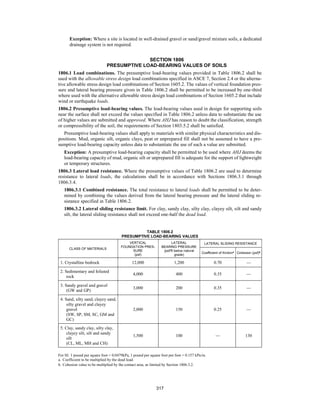
![318
1806.3.3 Increase for depth. The lateral bearing pressures specified in Table 1806.2 shall be permit-
ted to be increased by the tabular value for each additional foot (305 mm) of depth to a value that is
not greater than 15 times the tabular value.
1806.3.4 Increase for poles. Isolated poles for uses such as flagpoles or signs and poles used to sup-
port buildings that are not adversely affected by a 1
/2-inch (12.7 mm) motion at the ground surface
due to short-term lateral loads shall be permitted to be designed using lateral bearing pressures equal
to two times the tabular values.
SECTION 1807
FOUNDATION WALLS, RETAINING WALLS AND EMBEDDED POSTS AND POLES
1807.1 Foundation walls. Foundation walls shall be designed and constructed in accordance with Sec-
tions 1807.1.1 through 1807.1.6. Foundation walls shall be supported by foundations designed in accord-
ance with Section 1808.
1807.1.1 Design lateral soil loads. Foundation walls shall be designed for the lateral soil loads set
forth in Section 1610.
1807.1.2 Unbalanced backfill height. Unbalanced backfill height is the difference in height between
the exterior finish ground level and the lower of the top of the concrete footing that supports the
foundation wall or the interior finish ground level. Where an interior concrete slab on grade is pro-
vided and is in contact with the interior surface of the foundation wall, the unbalanced backfill height
shall be permitted to be measured from the exterior finish ground level to the top of the interior con-
crete slab.
1807.1.3 Rubble stone foundation walls. Foundation walls of rough or random rubble stone shall be
not less than 16 inches (406 mm) thick. Rubble stone shall not be used for foundation walls of struc-
tures assigned to Seismic Design Category C, D, E or F.
1807.1.4 Permanent wood foundation systems. This section is intentionally left blank.
1807.1.5 Concrete and masonry foundation walls. Concrete and masonry foundation walls shall be
designed in accordance with Chapter 19 or 21, as applicable.
Exception: Concrete and masonry foundation walls shall be permitted to be designed and con-
structed in accordance with Section 1807.1.6.
1807.1.6 Prescriptive design of concrete and masonry foundation walls. Concrete and masonry
foundation walls that are laterally supported at the top and bottom shall be permitted to be designed
and constructed in accordance with this section.
1807.1.6.1 Foundation wall thickness. The thickness of prescriptively designed foundation walls
shall be not less than the thickness of the wall supported, except that foundation walls of not less
than 8-inch (203 mm) nominal width shall be permitted to support brick-veneered frame walls and
10-inch-wide (254 mm) cavity walls provided that the requirements of Section 1807.1.6.2 or
1807.1.6.3 are met.
1807.1.6.2 Concrete foundation walls. Concrete foundation walls shall comply with the follow-
ing:
1. The thickness shall comply with the requirements of Table 1807.1.6.2.
2. The size and spacing of vertical reinforcement shown in Table 1807.1.6.2 are based on the
use of reinforcement with a minimum yield strength of 60,000 pounds per square inch (psi)
(414 MPa). Vertical reinforcement with a minimum yield strength of 40,000 psi (276 MPa)
or 50,000 psi (345 MPa) shall be permitted, provided that the same size bar is used and the
spacing shown in the table is reduced by multiplying the spacing by 0.67 or 0.83, respec-
tively.
3. Vertical reinforcement, where required, shall be placed nearest the inside face of the wall a
distance, d, from the outside face (soil face) of the wall. The distance, d, is equal to the wall
thickness, t, minus 1.25 inches (32 mm) plus one-half the bar diameter, db, [d = t - (1.25 + db /
2)]. The reinforcement shall be placed within a tolerance of ± 3
/8 inch (9.5 mm) where d is less
than or equal to 8 inches (203 mm) or ± 1
/2 inch (12.7 mm) where d is greater than 8 inches
(203 mm).
4. In lieu of the reinforcement shown in Table 1807.1.6.2, smaller reinforcing bar sizes with
closer spacings that provide an equivalent cross-sectional area of reinforcement per unit
length shall be permitted.](https://image.slidesharecdn.com/chapter18-250612013228-348b444f/85/chapter-18-building-code-of-pakistan-pdf-10-320.jpg)
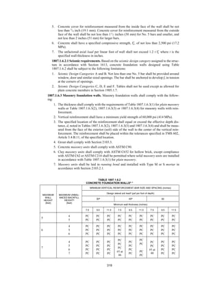
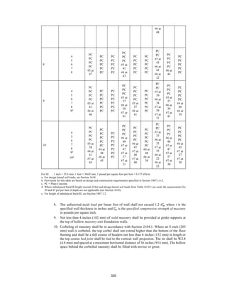
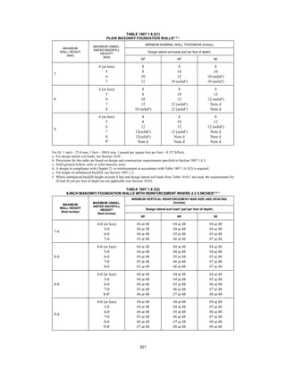

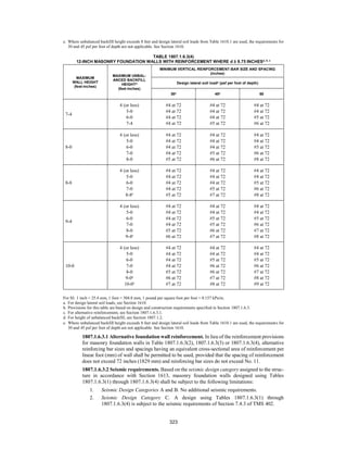
![324
3. Seismic Design Category D. A design using Tables 1807.1.6.3(2) through
1807.1.6.3(4) is subject to the seismic requirements of Section 7.4.4 of TMS 402.
4. Seismic Design Categories E and F. A design using Tables 1807.1.6.3(2) through
1807.1.6.3(4) is subject to the seismic requirements of Section 7.4.5 of TMS 402.
1807.2 Retaining walls. Retaining walls shall be designed in accordance with Sections 1807.2.1 through
1807.2.4.
1807.2.1 General. Retaining walls shall be designed to ensure stability against overturning, sliding,
excessive foundation pressure and water uplift.
1807.2.2 Design lateral soil loads. Retaining walls shall be designed for the lateral soil loads set forth
in Section 1610. For structures assigned to Seismic Design Category D, E, or F, the design of retaining
walls supporting more than 6 feet (1829 mm) of backfill height shall incorporate the additional seismic
lateral earth pressure in accordance with the geotechnical investigation where required in Section
1803.2.
1807.2.3 Safety factor. Retaining walls shall be designed to resist the lateral action of soil to produce
sliding and overturning with a minimum safety factor of 1.5 in each case. The load combinations of
Section 1605 shall not apply to this requirement. Instead, design shall be based on 0.7 times nominal
earthquake loads, 1.0 times other nominal loads, and investigation with one or more of the variable
loads set to zero. The safety factor against lateral sliding shall be taken as the available soil resistance
at the base of the retaining wall foundation divided by the net lateral force applied to the retaining
wall.
Exception: Where earthquake loads are included, the minimum safety factor for retaining wall
sliding and overturning shall be 1.1.
1807.2.4 Segmental retaining walls. Dry-cast concrete units used in the construction of segmental
retaining walls shall comply with ASTM C1372.
1807.3 Embedded posts and poles. Designs to resist both axial and lateral loads employing posts or
poles as columns embedded in earth or in concrete footings in earth shall be in accordance with Sections
1807.3.1 through 1807.3.3.
1807.3.1 Limitations. The design procedures outlined in this section are subject to the following
limitations:
1. The frictional resistance for structural walls and slabs on silts and clays shall be limited to one-
half of the normal force imposed on the soil by the weight of the footing or slab.
2. Posts embedded in earth shall not be used to provide lateral support for structural or nonstruc-
tural materials such as plaster, masonry or concrete unless bracing is provided that develops
the limited deflection required.
Wood poles shall be treated in accordance with AWPA U1 for sawn timber posts (Commodity
Specification A, Use Category 4B) and for round timber posts (Commodity Specification B, Use Cat-
egory 4B).
1807.3.2 Design criteria. The depth to resist lateral loads shall be determined using the design criteria
established in Sections 1807.3.2.1 through 1807.3.2.3, or by other methods approved by AHJ.
1807.3.2.1 Nonconstrained. The following formula shall be used in determining the depth of em-
bedment required to resist lateral loads where lateral constraint is not provided at the ground sur-
face, such as by a rigid floor or rigid ground surface pavement, and where lateral constraint is not
provided above the ground surface, such as by a structural diaphragm.
d = 0.5A{1 + [1 + (4.36h/A)]1/2
} (Equation 18-1)
where:
A = 2.34P/(S1b).
b = Diameter of round post or footing or diagonal dimension of square post or footing, feet (m).
d = Depth of embedment in earth in feet (m) but not over 12 feet (3658 mm) for purpose of
computing lateral pressure.
h = Distance in feet (m) from ground surface to point of application of “P.”
P = Applied lateral force in pounds (kN).
S1 = Allowable lateral soil-bearing pressure as set forth in Section 1806.2 based on a depth of
one-third the depth of embedment in pounds per square foot (psf) (kPa).](https://image.slidesharecdn.com/chapter18-250612013228-348b444f/85/chapter-18-building-code-of-pakistan-pdf-16-320.jpg)