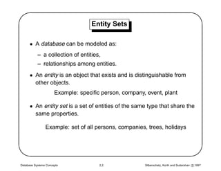
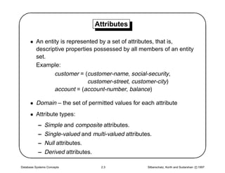
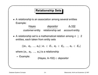
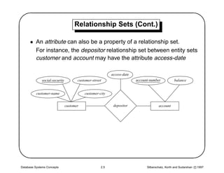
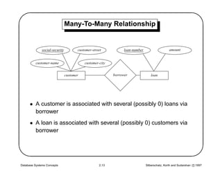
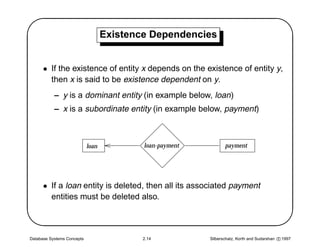
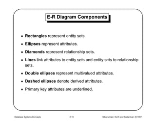
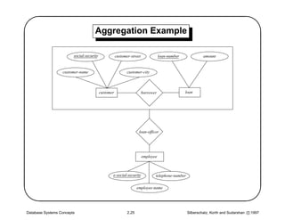
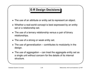
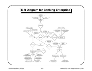
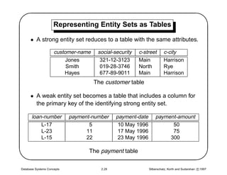
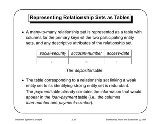
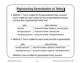
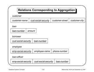
SlideShare a Scribd company logo
'                 Chapter 2: Entity-Relationship Model
                                                                                          $
      • Entity Sets
      • Relationship Sets
      • Design Issues
      • Mapping Constraints
      • Keys
      • E–R Diagram


&                                                                                         
      • Extended E-R Features
      • Design of an E-R Database Schema
      • Reduction of an E-R Schema to Tables


Database Systems Concepts        2.1           Silberschatz, Korth and Sudarshan c 1997
'                                  Entity Sets
                                                                                                  $
      • A database can be modeled as:
           – a collection of entities,
           – relationships among entities.
      • An entity is an object that exists and is distinguishable from
        other objects.
                      Example: specific person, company, event, plant

      • An entity set is a set of entities of the same type that share the
        same properties.


                Example: set of all persons, companies, trees, holidays


Database Systems Concepts             2.2              Silberschatz, Korth and Sudarshan c 1997
'                                  Attributes
                                                                                                $
      • An entity is represented by a set of attributes, that is,
        descriptive properties possessed by all members of an entity
        set.
        Example:
               customer = (customer-name, social-security,
                            customer-street, customer-city)
               account = (account-number, balance)

      • Domain – the set of permitted values for each attribute
      • Attribute types:


           – Simple and composite attributes.
           – Single-valued and multi-valued attributes.
           – Null attributes.
           – Derived attributes.

Database Systems Concepts           2.3              Silberschatz, Korth and Sudarshan c 1997
'                               Relationship Sets
                                                                                                       $
      • A relationship is an association among several entities
        Example:
                    Hayes            depositor         A-102
                     customer entity    relationship set    account entity

      • A relationship set is a mathematical relation among n ≥ 2
        entities, each taken from entity sets

                   {(e1 , e2 , ..., en ) | e1 ∈ E1 , e2 ∈ E2 , ..., en ∈ En }


          where (e1 , e2 , ..., en ) is a relationship
           – Example:
                                  (Hayes, A-102) ∈ depositor


Database Systems Concepts               2.4                 Silberschatz, Korth and Sudarshan c 1997
'                                    Relationship Sets (Cont.)
                                                                                                                          $
      • An attribute can also be a property of a relationship set.
        For instance, the depositor relationship set between entity sets
        customer and account may have the attribute access-date

                                                           access-date
              social-security          customer-street                   account-number           balance


          customer-name                    customer-city


                                customer                    depositor                  account


Database Systems Concepts                            2.5                       Silberschatz, Korth and Sudarshan c 1997
'                           Degree of a Relationship Set
                                                                                                $
      • Refers to number of entity sets that participate in a relationship
        set.
      • Relationship sets that involve two entity sets are binary (or
        degree two). Generally, most relationship sets in a database
        system are binary.
      • Relationship sets may involve more than two entity sets.
        The entity sets customer, loan, and branch may be linked by
        the ternary (degree three) relationship set CLB.


Database Systems Concepts              2.6           Silberschatz, Korth and Sudarshan c 1997
'                                                Roles
                                                                                                                     $
   Entity sets of a relationship need not be distinct

                                     employee-name


                       e-social-security               telephone-number

                                                               manager
                                           employee                          works-for
                                                                worker


      • The labels “manager” and “worker” are called roles; they
        specify how employee entities interact via the works-for


        relationship set.
      • Roles are indicated in E-R diagrams by labeling the lines that
        connect diamonds to rectangles.
      • Role labels are optional, and are used to clarify semantics of
        the relationship

Database Systems Concepts                        2.7                      Silberschatz, Korth and Sudarshan c 1997
'                            Design Issues
                                                                                                $
      • Use of entity sets vs. attributes
        Choice mainly depends on the structure of the enterprise being
        modeled, and on the semantics associated with the attribute in
        question.
      • Use of entity sets vs. relationship sets
        Possible guideline is to designate a relationship set to describe
        an action that occurs between entities
      • Binary versus n-ary relationship sets


        Although it is possible to replace a nonbinary (n-ary, for n  2)
        relationship set by a number of distinct binary relationship sets,
        a n-ary relationship set shows more clearly that several entities
        participate in a single relationship.


Database Systems Concepts         2.8                Silberschatz, Korth and Sudarshan c 1997
'                           Mapping Cardinalities
                                                                                               $
      • Express the number of entities to which another entity can be
        associated via a relationship set.
      • Most useful in describing binary relationship sets.
      • For a binary relationship set the mapping cardinality must be
        one of the following types:
           – One to one
           – One to many
           – Many to one


           – Many to many
      • We distinguish among these types by drawing either a directed
        line (→), signifying “one,” or an undirected line (—), signifying
        “many,” between the relationship set and the entity set.


Database Systems Concepts          2.9              Silberschatz, Korth and Sudarshan c 1997
'                                One-To-One Relationship
                                                                                                                          $
             social-security          customer-street            loan-number                   amount


          customer-name                   customer-city


                               customer                    borrower               loan


      • A customer is associated with at most one loan via the
        relationship borrower


      • A loan is associated with at most one customer via borrower


Database Systems Concepts                           2.10                       Silberschatz, Korth and Sudarshan c 1997
'        One-To-Many and Many-to-One Relationships
                                                                                                                                $
             social-security          customer-street                  loan-number                   amount


          customer-name                   customer-city


                               customer                          borrower               loan


                                                           (a)


             social-security          customer-street                  loan-number                   amount


          customer-name                   customer-city


                               customer                          borrower               loan


                                                           (b)


Database Systems Concepts                           2.11                             Silberschatz, Korth and Sudarshan c 1997
'                One-To-Many and Many-to-One (Cont.)
                                                                                               $
      • In the one-to-many relationship (a), a loan is associated with at
        most one customer via borrower; a customer is associated with
        several (including 0) loans via borrower

      • In the many-to-one relationship (b), a loan is associated with
        several (including 0) customers via borrower; a customer is
        associated with at most one loan via borrower


Database Systems Concepts        2.12               Silberschatz, Korth and Sudarshan c 1997
'                               Many-To-Many Relationship
                                                                                                                          $
              social-security          customer-street           loan-number                   amount


          customer-name                    customer-city


                                customer                   borrower               loan


      • A customer is associated with several (possibly 0) loans via
        borrower


      • A loan is associated with several (possibly 0) customers via
        borrower


Database Systems Concepts                           2.13                       Silberschatz, Korth and Sudarshan c 1997
'                                  Existence Dependencies
                                                                                                     $
      • If the existence of entity x depends on the existence of entity y,
        then x is said to be existence dependent on y.
           – y is a dominant entity (in example below, loan)
           – x is a subordinate entity (in example below, payment)


                            loan           loan-payment          payment


      • If a loan entity is deleted, then all its associated payment
        entities must be deleted also.


Database Systems Concepts                  2.14           Silberschatz, Korth and Sudarshan c 1997
'                                   Keys
                                                                                                $
      • A super key of an entity set is a set of one or more attributes
        whose values uniquely determine each entity
      • A candidate key of an entity set is a minimal super key
           – social-security is candidate key of customer
           – account-number is candidate key of account
      • Although several candidate keys may exist, one of the
        candidate keys is selected to be the primary key.
      • The combination of primary keys of the participating entity sets
        forms a candidate key of a relationship set.


           – must consider the mapping cardinality and the semantics of
             the relationship set when selecting the primary key.
           – (social-security, account-number) is the primary key of
             depositor

Database Systems Concepts          2.15              Silberschatz, Korth and Sudarshan c 1997
'                           E-R Diagram Components
                                                                                                 $
      • Rectangles represent entity sets.
      • Ellipses represent attributes.
      • Diamonds represent relationship sets.
      • Lines link attributes to entity sets and entity sets to relationship
        sets.
      • Double ellipses represent multivalued attributes.
      • Dashed ellipses denote derived attributes.


      • Primary key attributes are underlined.


Database Systems Concepts           2.16              Silberschatz, Korth and Sudarshan c 1997
'                           Weak Entity Sets
                                                                                                $
      • An entity set that does not have a primary key is referred to as
        a weak entity set.
      • The existence of a weak entity set depends on the existence of
        a strong entity set; it must relate to the strong set via a
        one-to-many relationship set.
      • The discriminator (or partial key) of a weak entity set is the set
        of attributes that distinguishes among all the entities of a weak
        entity set.


      • The primary key of a weak entity set is formed by the primary
        key of the strong entity set on which the weak entity set is
        existence dependent, plus the weak entity set’s discriminator.


Database Systems Concepts         2.17               Silberschatz, Korth and Sudarshan c 1997
'                                  Weak Entity Sets (Cont.)
                                                                                                                  $
      • We depict a weak entity set by double rectangles.
      • We underline the discriminator of a weak entity set with a
        dashed line.
      • payment-number – discriminator of the payment entity set
      • Primary key for payment – (loan-number, payment-number)

                                                                      payment-date

           loan-number               amount               payment-number             payment-amount


                            loan               loan-payment                payment


Database Systems Concepts                     2.18                     Silberschatz, Korth and Sudarshan c 1997
'                            Specialization
                                                                                                 $
      • Top-down design process; we designate subgroupings within
        an entity set that are distinctive from other entities in the set.

      • These subgroupings become lower-level entity sets that have
        attributes or participate in relationships that do not apply to the
        higher-level entity set.

      • Depicted by a triangle component labeled ISA (i.e.,
        savings-account “is an” account)


Database Systems Concepts          2.19               Silberschatz, Korth and Sudarshan c 1997
'                                    Specialization Example
                                                                                                                                             $
                                   account-number                     balance


                                                       account


                                                         ISA

                            interest-rate                                 overdraft-amount


                                    savings-account            checking-account


                                                                       ISA


                                            standard                  gold               senior


                     num-checks                 interest-payment                min-balance            date-of-birth


Database Systems Concepts                                      2.20                               Silberschatz, Korth and Sudarshan c 1997
'                            Generalization
                                                                                                $
      • A bottom-up design process – combine a number of entity sets
        that share the same features into a higher-level entity set

      • Specialization and generalization are simple inversions of each
        other; they are represented in an E-R diagram in the same way.

      • Attribute Inheritance – a lower-level entity set inherits all the
        attributes and relationship participation of the higher-level
        entity set to which it is linked.


Database Systems Concepts         2.21               Silberschatz, Korth and Sudarshan c 1997
'               Design Constraints on a Generalization
                                                                                             $
      • Constraint on which entities can be members of a given
        lower-level entity set.
           – condition-defined
           – user-defined
      • Constraint on whether or not entities may belong to more than
        one lower-level entity set within a single generalization.
           – disjoint
           – overlapping
      • Completeness constraint – specifies whether or not an entity in


        the higher-level entity set must belong to at least one of the
        lower-level entity sets within a generalization.
           – total
           – partial


Database Systems Concepts       2.22              Silberschatz, Korth and Sudarshan c 1997
'                                                     Aggregation
                                                                                                                                               $
      • Loan customers may be advised by a loan-officer.

                        social-security              customer-street                  loan-number            amount


                   customer-name                            customer-city


                                          customer                     borrower                     loan


                                                                       loan-officer


                                                                          employee


                                                      e-social-security          telephone-number

                                                                     employee-name


Database Systems Concepts                                     2.23                                  Silberschatz, Korth and Sudarshan c 1997
'                           Aggregation (Cont.)
                                                                                                   $
      • Relationship sets borrower and loan-officer represent the same
        information
      • Eliminate this redundancy via aggregation
           – Treat relationship as an abstract entity
           – Allows relationships between relationships
           – Abstraction of relationship into new entity
      • Without introducing redundancy, the following diagram


        represents that:
           – A customer takes out a loan
           – An employee may be a loan officer for a customer-loan pair


Database Systems Concepts          2.24                 Silberschatz, Korth and Sudarshan c 1997
'                                    Aggregation Example
                                                                                                                                            $
                        social-security              customer-street              loan-number             amount


                  customer-name                             customer-city


                                          customer                     borrower                 loan


                                                                    loan-officer


                                                                       employee


                                                 e-social-security            telephone-number

                                                                   employee-name


Database Systems Concepts                                   2.25                                 Silberschatz, Korth and Sudarshan c 1997
'                           E-R Design Decisions
                                                                                                $
      • The use of an attribute or entity set to represent an object.
      • Whether a real-world concept is best expressed by an entity
        set or a relationship set.
      • The use of a ternary relationship versus a pair of binary
        relationships.
      • The use of a strong or weak entity set.
      • The use of generalization – contributes to modularity in the


        design.
      • The use of aggregation – can treat the aggregate entity set as
        a single unit without concern for the details of its internal
        structure.


Database Systems Concepts         2.26               Silberschatz, Korth and Sudarshan c 1997
'                   E-R Diagram for Banking Enterprise
                                                                                                                                                                                            $
                                                                           branch-city

                                                           branch-name                        assets


                                                                              branch


                                                                         loan-branch

                                   social-security                                                                                         payment-date

                                                     customer-street                                                          payment-number         payment-amount
                            customer-name                                                loan-number
                                                           customer-city
                                                                                                             amount


                                                customer                     borrower              loan                loan-payment              payment


                                                                                                       access-date

                                                                                                                         account-number             balance
                                                  cust-banker                  type

                                                                                                        depositor                      account


                                                                    manager
                                                   employee                           works-for                                            ISA
                                                                    worker


                            e-social-security                      employee-name                                         savings-account     checking-account


                              dependent-name                    telephone-number


                               employment-length                start-date                                           interest-rate                   overdraft-amount


Database Systems Concepts                                                         2.27                                                           Silberschatz, Korth and Sudarshan c 1997
'                Reduction of an E-R Schema to Tables
                                                                                               $
      • Primary keys allow entity sets and relationship sets to be
        expressed uniformly as tables which represent the contents of
        the database.
      • A database which conforms to an E-R diagram can be
        represented by a collection of tables.
      • For each entity set and relationship set there is a unique table
        which is assigned the name of the corresponding entity set or
        relationship set.


      • Each table has a number of columns (generally corresponding
        to attributes), which have unique names.
      • Converting an E-R diagram to a table format is the basis for
        deriving a relational database design from an E-R diagram.


Database Systems Concepts        2.28               Silberschatz, Korth and Sudarshan c 1997
'                    Representing Entity Sets as Tables
                                                                                                        $
      • A strong entity set reduces to a table with the same attributes.

                     customer-name    social-security   c-street       c-city
                          Jones        321-12-3123      Main           Harrison
                          Smith        019-28-3746      North          Rye
                         Hayes         677-89-9011      Main           Harrison
                                     The customer table

      • A weak entity set becomes a table that includes a column for
        the primary key of the identifying strong entity set.

      loan-number           payment-number    payment-date       payment-amount


          L-17                     5           10 May 1996             50
          L-23                    11           17 May 1996             75
          L-15                    22           23 May 1996            300

                                   The payment table

Database Systems Concepts              2.29                  Silberschatz, Korth and Sudarshan c 1997
'            Representing Relationship Sets as Tables
                                                                                                         $
      • A many-to-many relationship set is represented as a table with
        columns for the primary keys of the two participating entity
        sets, and any descriptive attributes of the relationship set.

                      social-security     account-number      access-date
                            ...                  ...                    ...

                                        The depositor table

      • The table corresponding to a relationship set linking a weak


        entity set to its identifying strong entity set is redundant.
        The payment table already contains the information that would
        appear in the loan-payment table (i.e., the columns
        loan-number and payment-number).


Database Systems Concepts                 2.30                Silberschatz, Korth and Sudarshan c 1997
'                Representing Generalization as Tables
                                                                                                       $
      • Method 1: Form a table for the generalized entity account
        Form a table for each entity set that is generalized (include
        primary key of generalized entity set)

                            table                 table attributes
                 account              account-number, balance, account-type
                 savings-account      account-number, interest-rate
                 checking-account     account-number, overdraft-amount

      • Method 2: Form a table for each entity set that is generalized


                        table                     table attributes
              savings-account       account-number, balance, interest-rate
              checking-account      account-number, balance, overdraft-amount

          Method 2 has no table for generalized entity account

Database Systems Concepts               2.31                Silberschatz, Korth and Sudarshan c 1997
'             Relations Corresponding to Aggregation
                                                                                                         $
     customer

     customer-name            cust-social-security   customer-street        customer-city

     loan

     loan-number            amount

     borrower

     cust-social-security        loan-number

     employee


     emp-social-security         employee-name       phone-number

     loan-officer

     emp-social-security         cust-social-security   loan-number


Database Systems Concepts                 2.32                Silberschatz, Korth and Sudarshan c 1997

More Related Content

Viewers also liked

Database Modeling Using Entity.. Weak And Strong Entity Types
Database Modeling Using Entity.. Weak And Strong Entity TypesDatabase Modeling Using Entity.. Weak And Strong Entity Types
Database Modeling Using Entity.. Weak And Strong Entity Typesaakanksha s
 
Desigining of Database - ER Model
Desigining of Database - ER ModelDesigining of Database - ER Model
Desigining of Database - ER Model
Ajay Chhimpa
 
Database Design E R 2009
Database Design E R 2009Database Design E R 2009
Database Design E R 2009Cathie101
 
03 Ch3 Notes Revised
03 Ch3 Notes Revised03 Ch3 Notes Revised
03 Ch3 Notes Revised
guest6f408c
 
Er Model Nandha&Mani
Er Model Nandha&ManiEr Model Nandha&Mani
Er Model Nandha&Maniguest1e0229a
 
Dbms ii mca-ch3-er-model-2013
Dbms ii mca-ch3-er-model-2013Dbms ii mca-ch3-er-model-2013
Dbms ii mca-ch3-er-model-2013
Prosanta Ghosh
 
Entity-Relationship Diagrams ERD
Entity-Relationship Diagrams ERDEntity-Relationship Diagrams ERD
Entity-Relationship Diagrams ERD
torp42
 
ER model to Relational model mapping
ER model to Relational model mappingER model to Relational model mapping
ER model to Relational model mappingShubham Saini
 
Special lecture er diagram
Special lecture er diagramSpecial lecture er diagram
Special lecture er diagram
Niaz Ali
 
Entity Relationship Diagram2
Entity Relationship Diagram2Entity Relationship Diagram2
Entity Relationship Diagram2
sadeenedian08
 
2. Entity Relationship Model in DBMS
2. Entity Relationship Model in DBMS2. Entity Relationship Model in DBMS
2. Entity Relationship Model in DBMSkoolkampus
 
Computer Languages....ppt
Computer Languages....pptComputer Languages....ppt
Computer Languages....ppthashgeneration
 
How to Draw an Effective ER diagram
How to Draw an Effective ER diagramHow to Draw an Effective ER diagram
How to Draw an Effective ER diagramTech_MX
 
Entity relationship diagram
Entity relationship diagramEntity relationship diagram
Entity relationship diagram
Haseeb
 

Viewers also liked (18)

Database Modeling Using Entity.. Weak And Strong Entity Types
Database Modeling Using Entity.. Weak And Strong Entity TypesDatabase Modeling Using Entity.. Weak And Strong Entity Types
Database Modeling Using Entity.. Weak And Strong Entity Types
 
Desigining of Database - ER Model
Desigining of Database - ER ModelDesigining of Database - ER Model
Desigining of Database - ER Model
 
Database Design E R 2009
Database Design E R 2009Database Design E R 2009
Database Design E R 2009
 
Er model
Er modelEr model
Er model
 
Unit 02 dbms
Unit 02 dbmsUnit 02 dbms
Unit 02 dbms
 
03 Ch3 Notes Revised
03 Ch3 Notes Revised03 Ch3 Notes Revised
03 Ch3 Notes Revised
 
Er Model Nandha&Mani
Er Model Nandha&ManiEr Model Nandha&Mani
Er Model Nandha&Mani
 
Dbms ii mca-ch3-er-model-2013
Dbms ii mca-ch3-er-model-2013Dbms ii mca-ch3-er-model-2013
Dbms ii mca-ch3-er-model-2013
 
Entity-Relationship Diagrams ERD
Entity-Relationship Diagrams ERDEntity-Relationship Diagrams ERD
Entity-Relationship Diagrams ERD
 
ER model to Relational model mapping
ER model to Relational model mappingER model to Relational model mapping
ER model to Relational model mapping
 
RDBMS ERD
RDBMS ERDRDBMS ERD
RDBMS ERD
 
Special lecture er diagram
Special lecture er diagramSpecial lecture er diagram
Special lecture er diagram
 
Atomic bomb blasting of Hiroshima and Nagasaki .ppt
Atomic bomb blasting of Hiroshima and Nagasaki .pptAtomic bomb blasting of Hiroshima and Nagasaki .ppt
Atomic bomb blasting of Hiroshima and Nagasaki .ppt
 
Entity Relationship Diagram2
Entity Relationship Diagram2Entity Relationship Diagram2
Entity Relationship Diagram2
 
2. Entity Relationship Model in DBMS
2. Entity Relationship Model in DBMS2. Entity Relationship Model in DBMS
2. Entity Relationship Model in DBMS
 
Computer Languages....ppt
Computer Languages....pptComputer Languages....ppt
Computer Languages....ppt
 
How to Draw an Effective ER diagram
How to Draw an Effective ER diagramHow to Draw an Effective ER diagram
How to Draw an Effective ER diagram
 
Entity relationship diagram
Entity relationship diagramEntity relationship diagram
Entity relationship diagram
 

Similar to Chap2

DBMS Class 3
DBMS Class 3DBMS Class 3
DataBase ch2
DataBase ch2DataBase ch2
DataBase ch2
ayman_alawin
 
Basic er diagram
Basic er diagramBasic er diagram
Basic er diagram
Hannan Riad
 
39f1b9a797dbms chapter2 b.sc2
39f1b9a797dbms chapter2 b.sc239f1b9a797dbms chapter2 b.sc2
39f1b9a797dbms chapter2 b.sc2Mukund Trivedi
 
39f1b9a797dbms chapter2 b.sc2 (1)
39f1b9a797dbms chapter2 b.sc2 (1)39f1b9a797dbms chapter2 b.sc2 (1)
39f1b9a797dbms chapter2 b.sc2 (1)Mukund Trivedi
 
Ch2
Ch2Ch2
U2_ER_modeling.pptx
U2_ER_modeling.pptxU2_ER_modeling.pptx
U2_ER_modeling.pptx
ssusera7b660
 
E-r Model.ppt
E-r Model.pptE-r Model.ppt
E-r Model.ppt
ManoRanjani30
 
DBA
DBADBA
Datastage database design and data modeling ppt 4
Datastage database design and data modeling ppt 4Datastage database design and data modeling ppt 4
Datastage database design and data modeling ppt 4
Vibrant Technologies & Computers
 
Chapter 2. Concepctual design -.pptx
Chapter 2. Concepctual design -.pptxChapter 2. Concepctual design -.pptx
Chapter 2. Concepctual design -.pptx
santosh96234
 
Revision ch 3
Revision ch 3Revision ch 3
Revision ch 3
Rupali Rana
 
Basic concepts of Data and Databases
Basic concepts of Data and Databases Basic concepts of Data and Databases
Basic concepts of Data and Databases
Tharindu Weerasinghe
 
Er model
Er modelEr model
Er model
slidenageswaran
 
Database design
Database designDatabase design
Database design
Jennifer Polack
 

Similar to Chap2 (20)

DBMS Class 3
DBMS Class 3DBMS Class 3
DBMS Class 3
 
DataBase ch2
DataBase ch2DataBase ch2
DataBase ch2
 
Basic er diagram
Basic er diagramBasic er diagram
Basic er diagram
 
39f1b9a797dbms chapter2 b.sc2
39f1b9a797dbms chapter2 b.sc239f1b9a797dbms chapter2 b.sc2
39f1b9a797dbms chapter2 b.sc2
 
39f1b9a797dbms chapter2 b.sc2 (1)
39f1b9a797dbms chapter2 b.sc2 (1)39f1b9a797dbms chapter2 b.sc2 (1)
39f1b9a797dbms chapter2 b.sc2 (1)
 
Ch2
Ch2Ch2
Ch2
 
Ch6
Ch6Ch6
Ch6
 
U2_ER_modeling.pptx
U2_ER_modeling.pptxU2_ER_modeling.pptx
U2_ER_modeling.pptx
 
ch2.ppt
ch2.pptch2.ppt
ch2.ppt
 
ER.ppt
ER.pptER.ppt
ER.ppt
 
E-r Model.ppt
E-r Model.pptE-r Model.ppt
E-r Model.ppt
 
DBA
DBADBA
DBA
 
10287 lecture5(2)
10287 lecture5(2)10287 lecture5(2)
10287 lecture5(2)
 
Datastage database design and data modeling ppt 4
Datastage database design and data modeling ppt 4Datastage database design and data modeling ppt 4
Datastage database design and data modeling ppt 4
 
2 er
2 er2 er
2 er
 
Chapter 2. Concepctual design -.pptx
Chapter 2. Concepctual design -.pptxChapter 2. Concepctual design -.pptx
Chapter 2. Concepctual design -.pptx
 
Revision ch 3
Revision ch 3Revision ch 3
Revision ch 3
 
Basic concepts of Data and Databases
Basic concepts of Data and Databases Basic concepts of Data and Databases
Basic concepts of Data and Databases
 
Er model
Er modelEr model
Er model
 
Database design
Database designDatabase design
Database design
 

Chap2

  • 1. ' Chapter 2: Entity-Relationship Model $ • Entity Sets • Relationship Sets • Design Issues • Mapping Constraints • Keys • E–R Diagram & • Extended E-R Features • Design of an E-R Database Schema • Reduction of an E-R Schema to Tables Database Systems Concepts 2.1 Silberschatz, Korth and Sudarshan c 1997
  • 2. ' Entity Sets $ • A database can be modeled as: – a collection of entities, – relationships among entities. • An entity is an object that exists and is distinguishable from other objects. Example: specific person, company, event, plant • An entity set is a set of entities of the same type that share the same properties. Example: set of all persons, companies, trees, holidays Database Systems Concepts 2.2 Silberschatz, Korth and Sudarshan c 1997
  • 3. ' Attributes $ • An entity is represented by a set of attributes, that is, descriptive properties possessed by all members of an entity set. Example: customer = (customer-name, social-security, customer-street, customer-city) account = (account-number, balance) • Domain – the set of permitted values for each attribute • Attribute types: – Simple and composite attributes. – Single-valued and multi-valued attributes. – Null attributes. – Derived attributes. Database Systems Concepts 2.3 Silberschatz, Korth and Sudarshan c 1997
  • 4. ' Relationship Sets $ • A relationship is an association among several entities Example: Hayes depositor A-102 customer entity relationship set account entity • A relationship set is a mathematical relation among n ≥ 2 entities, each taken from entity sets {(e1 , e2 , ..., en ) | e1 ∈ E1 , e2 ∈ E2 , ..., en ∈ En } where (e1 , e2 , ..., en ) is a relationship – Example: (Hayes, A-102) ∈ depositor Database Systems Concepts 2.4 Silberschatz, Korth and Sudarshan c 1997
  • 5. ' Relationship Sets (Cont.) $ • An attribute can also be a property of a relationship set. For instance, the depositor relationship set between entity sets customer and account may have the attribute access-date access-date social-security customer-street account-number balance customer-name customer-city customer depositor account Database Systems Concepts 2.5 Silberschatz, Korth and Sudarshan c 1997
  • 6. ' Degree of a Relationship Set $ • Refers to number of entity sets that participate in a relationship set. • Relationship sets that involve two entity sets are binary (or degree two). Generally, most relationship sets in a database system are binary. • Relationship sets may involve more than two entity sets. The entity sets customer, loan, and branch may be linked by the ternary (degree three) relationship set CLB. Database Systems Concepts 2.6 Silberschatz, Korth and Sudarshan c 1997
  • 7. ' Roles $ Entity sets of a relationship need not be distinct employee-name e-social-security telephone-number manager employee works-for worker • The labels “manager” and “worker” are called roles; they specify how employee entities interact via the works-for relationship set. • Roles are indicated in E-R diagrams by labeling the lines that connect diamonds to rectangles. • Role labels are optional, and are used to clarify semantics of the relationship Database Systems Concepts 2.7 Silberschatz, Korth and Sudarshan c 1997
  • 8. ' Design Issues $ • Use of entity sets vs. attributes Choice mainly depends on the structure of the enterprise being modeled, and on the semantics associated with the attribute in question. • Use of entity sets vs. relationship sets Possible guideline is to designate a relationship set to describe an action that occurs between entities • Binary versus n-ary relationship sets Although it is possible to replace a nonbinary (n-ary, for n 2) relationship set by a number of distinct binary relationship sets, a n-ary relationship set shows more clearly that several entities participate in a single relationship. Database Systems Concepts 2.8 Silberschatz, Korth and Sudarshan c 1997
  • 9. ' Mapping Cardinalities $ • Express the number of entities to which another entity can be associated via a relationship set. • Most useful in describing binary relationship sets. • For a binary relationship set the mapping cardinality must be one of the following types: – One to one – One to many – Many to one – Many to many • We distinguish among these types by drawing either a directed line (→), signifying “one,” or an undirected line (—), signifying “many,” between the relationship set and the entity set. Database Systems Concepts 2.9 Silberschatz, Korth and Sudarshan c 1997
  • 10. ' One-To-One Relationship $ social-security customer-street loan-number amount customer-name customer-city customer borrower loan • A customer is associated with at most one loan via the relationship borrower • A loan is associated with at most one customer via borrower Database Systems Concepts 2.10 Silberschatz, Korth and Sudarshan c 1997
  • 11. ' One-To-Many and Many-to-One Relationships $ social-security customer-street loan-number amount customer-name customer-city customer borrower loan (a) social-security customer-street loan-number amount customer-name customer-city customer borrower loan (b) Database Systems Concepts 2.11 Silberschatz, Korth and Sudarshan c 1997
  • 12. ' One-To-Many and Many-to-One (Cont.) $ • In the one-to-many relationship (a), a loan is associated with at most one customer via borrower; a customer is associated with several (including 0) loans via borrower • In the many-to-one relationship (b), a loan is associated with several (including 0) customers via borrower; a customer is associated with at most one loan via borrower Database Systems Concepts 2.12 Silberschatz, Korth and Sudarshan c 1997
  • 13. ' Many-To-Many Relationship $ social-security customer-street loan-number amount customer-name customer-city customer borrower loan • A customer is associated with several (possibly 0) loans via borrower • A loan is associated with several (possibly 0) customers via borrower Database Systems Concepts 2.13 Silberschatz, Korth and Sudarshan c 1997
  • 14. ' Existence Dependencies $ • If the existence of entity x depends on the existence of entity y, then x is said to be existence dependent on y. – y is a dominant entity (in example below, loan) – x is a subordinate entity (in example below, payment) loan loan-payment payment • If a loan entity is deleted, then all its associated payment entities must be deleted also. Database Systems Concepts 2.14 Silberschatz, Korth and Sudarshan c 1997
  • 15. ' Keys $ • A super key of an entity set is a set of one or more attributes whose values uniquely determine each entity • A candidate key of an entity set is a minimal super key – social-security is candidate key of customer – account-number is candidate key of account • Although several candidate keys may exist, one of the candidate keys is selected to be the primary key. • The combination of primary keys of the participating entity sets forms a candidate key of a relationship set. – must consider the mapping cardinality and the semantics of the relationship set when selecting the primary key. – (social-security, account-number) is the primary key of depositor Database Systems Concepts 2.15 Silberschatz, Korth and Sudarshan c 1997
  • 16. ' E-R Diagram Components $ • Rectangles represent entity sets. • Ellipses represent attributes. • Diamonds represent relationship sets. • Lines link attributes to entity sets and entity sets to relationship sets. • Double ellipses represent multivalued attributes. • Dashed ellipses denote derived attributes. • Primary key attributes are underlined. Database Systems Concepts 2.16 Silberschatz, Korth and Sudarshan c 1997
  • 17. ' Weak Entity Sets $ • An entity set that does not have a primary key is referred to as a weak entity set. • The existence of a weak entity set depends on the existence of a strong entity set; it must relate to the strong set via a one-to-many relationship set. • The discriminator (or partial key) of a weak entity set is the set of attributes that distinguishes among all the entities of a weak entity set. • The primary key of a weak entity set is formed by the primary key of the strong entity set on which the weak entity set is existence dependent, plus the weak entity set’s discriminator. Database Systems Concepts 2.17 Silberschatz, Korth and Sudarshan c 1997
  • 18. ' Weak Entity Sets (Cont.) $ • We depict a weak entity set by double rectangles. • We underline the discriminator of a weak entity set with a dashed line. • payment-number – discriminator of the payment entity set • Primary key for payment – (loan-number, payment-number) payment-date loan-number amount payment-number payment-amount loan loan-payment payment Database Systems Concepts 2.18 Silberschatz, Korth and Sudarshan c 1997
  • 19. ' Specialization $ • Top-down design process; we designate subgroupings within an entity set that are distinctive from other entities in the set. • These subgroupings become lower-level entity sets that have attributes or participate in relationships that do not apply to the higher-level entity set. • Depicted by a triangle component labeled ISA (i.e., savings-account “is an” account) Database Systems Concepts 2.19 Silberschatz, Korth and Sudarshan c 1997
  • 20. ' Specialization Example $ account-number balance account ISA interest-rate overdraft-amount savings-account checking-account ISA standard gold senior num-checks interest-payment min-balance date-of-birth Database Systems Concepts 2.20 Silberschatz, Korth and Sudarshan c 1997
  • 21. ' Generalization $ • A bottom-up design process – combine a number of entity sets that share the same features into a higher-level entity set • Specialization and generalization are simple inversions of each other; they are represented in an E-R diagram in the same way. • Attribute Inheritance – a lower-level entity set inherits all the attributes and relationship participation of the higher-level entity set to which it is linked. Database Systems Concepts 2.21 Silberschatz, Korth and Sudarshan c 1997
  • 22. ' Design Constraints on a Generalization $ • Constraint on which entities can be members of a given lower-level entity set. – condition-defined – user-defined • Constraint on whether or not entities may belong to more than one lower-level entity set within a single generalization. – disjoint – overlapping • Completeness constraint – specifies whether or not an entity in the higher-level entity set must belong to at least one of the lower-level entity sets within a generalization. – total – partial Database Systems Concepts 2.22 Silberschatz, Korth and Sudarshan c 1997
  • 23. ' Aggregation $ • Loan customers may be advised by a loan-officer. social-security customer-street loan-number amount customer-name customer-city customer borrower loan loan-officer employee e-social-security telephone-number employee-name Database Systems Concepts 2.23 Silberschatz, Korth and Sudarshan c 1997
  • 24. ' Aggregation (Cont.) $ • Relationship sets borrower and loan-officer represent the same information • Eliminate this redundancy via aggregation – Treat relationship as an abstract entity – Allows relationships between relationships – Abstraction of relationship into new entity • Without introducing redundancy, the following diagram represents that: – A customer takes out a loan – An employee may be a loan officer for a customer-loan pair Database Systems Concepts 2.24 Silberschatz, Korth and Sudarshan c 1997
  • 25. ' Aggregation Example $ social-security customer-street loan-number amount customer-name customer-city customer borrower loan loan-officer employee e-social-security telephone-number employee-name Database Systems Concepts 2.25 Silberschatz, Korth and Sudarshan c 1997
  • 26. ' E-R Design Decisions $ • The use of an attribute or entity set to represent an object. • Whether a real-world concept is best expressed by an entity set or a relationship set. • The use of a ternary relationship versus a pair of binary relationships. • The use of a strong or weak entity set. • The use of generalization – contributes to modularity in the design. • The use of aggregation – can treat the aggregate entity set as a single unit without concern for the details of its internal structure. Database Systems Concepts 2.26 Silberschatz, Korth and Sudarshan c 1997
  • 27. ' E-R Diagram for Banking Enterprise $ branch-city branch-name assets branch loan-branch social-security payment-date customer-street payment-number payment-amount customer-name loan-number customer-city amount customer borrower loan loan-payment payment access-date account-number balance cust-banker type depositor account manager employee works-for ISA worker e-social-security employee-name savings-account checking-account dependent-name telephone-number employment-length start-date interest-rate overdraft-amount Database Systems Concepts 2.27 Silberschatz, Korth and Sudarshan c 1997
  • 28. ' Reduction of an E-R Schema to Tables $ • Primary keys allow entity sets and relationship sets to be expressed uniformly as tables which represent the contents of the database. • A database which conforms to an E-R diagram can be represented by a collection of tables. • For each entity set and relationship set there is a unique table which is assigned the name of the corresponding entity set or relationship set. • Each table has a number of columns (generally corresponding to attributes), which have unique names. • Converting an E-R diagram to a table format is the basis for deriving a relational database design from an E-R diagram. Database Systems Concepts 2.28 Silberschatz, Korth and Sudarshan c 1997
  • 29. ' Representing Entity Sets as Tables $ • A strong entity set reduces to a table with the same attributes. customer-name social-security c-street c-city Jones 321-12-3123 Main Harrison Smith 019-28-3746 North Rye Hayes 677-89-9011 Main Harrison The customer table • A weak entity set becomes a table that includes a column for the primary key of the identifying strong entity set. loan-number payment-number payment-date payment-amount L-17 5 10 May 1996 50 L-23 11 17 May 1996 75 L-15 22 23 May 1996 300 The payment table Database Systems Concepts 2.29 Silberschatz, Korth and Sudarshan c 1997
  • 30. ' Representing Relationship Sets as Tables $ • A many-to-many relationship set is represented as a table with columns for the primary keys of the two participating entity sets, and any descriptive attributes of the relationship set. social-security account-number access-date ... ... ... The depositor table • The table corresponding to a relationship set linking a weak entity set to its identifying strong entity set is redundant. The payment table already contains the information that would appear in the loan-payment table (i.e., the columns loan-number and payment-number). Database Systems Concepts 2.30 Silberschatz, Korth and Sudarshan c 1997
  • 31. ' Representing Generalization as Tables $ • Method 1: Form a table for the generalized entity account Form a table for each entity set that is generalized (include primary key of generalized entity set) table table attributes account account-number, balance, account-type savings-account account-number, interest-rate checking-account account-number, overdraft-amount • Method 2: Form a table for each entity set that is generalized table table attributes savings-account account-number, balance, interest-rate checking-account account-number, balance, overdraft-amount Method 2 has no table for generalized entity account Database Systems Concepts 2.31 Silberschatz, Korth and Sudarshan c 1997
  • 32. ' Relations Corresponding to Aggregation $ customer customer-name cust-social-security customer-street customer-city loan loan-number amount borrower cust-social-security loan-number employee emp-social-security employee-name phone-number loan-officer emp-social-security cust-social-security loan-number Database Systems Concepts 2.32 Silberschatz, Korth and Sudarshan c 1997