Download to read offline
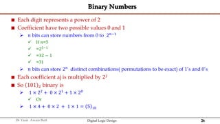
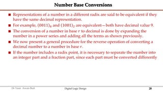
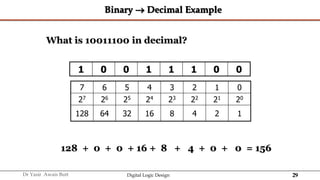
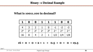
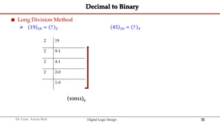
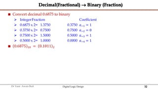
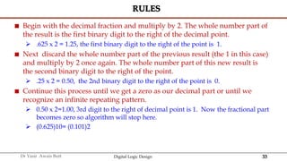
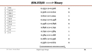
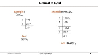
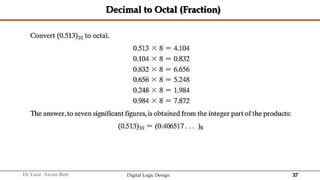

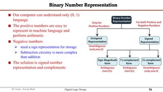

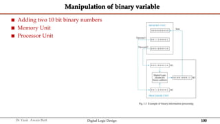


The document discusses digital systems and binary numbers. It defines a digital system as a system that processes, stores, and communicates information using discrete values. Digital systems have advantages like occupying minimum space and allowing for precise and accurate reproduction of information. The binary number system represents numbers using only two digits: 0 and 1. Each digit in a binary number represents a power of 2. The document also discusses converting between different number bases, like binary to decimal and vice versa, using place value and long division methods.


![[01] Exit Exam Preparation 2023 DLD.pptx](https://cdn.slidesharecdn.com/ss_thumbnails/01exitexampreparation2023dld-240125153029-e5ceb74d-thumbnail.jpg?width=640&height=640&fit=bounds)