Cembre 120sqmm LV Copper Cable Lugs - A24M

Cembre A24-M Copper Cable Lugs 120sqmm - designed to be crimped onto the copper conductor to enable low voltage (LV) cable termination via the crimped lug. Cembre A24-M - M8, M10, M12, M14, M16, M20 stud hole diameters (mm). Recommended crimping tools Cembre B35-50D, HT51, HT131-C. Cembre 120sqmm LV Copper Cable Lugs - A24M Cembre Copper Tube Crimping Lugs for Copper Conductors -Specification (CE Approved & UL Listed) Cembre copper cable lugs are specified to crimp stranded copper conductors to BS6360 Class 2 and Class 5 flexible copper cables, suitable for 600/1000v, 3.3kV and 11kV dry indoor cable termination when installed using suitably calibrated Cembre crimping tool and die sets. BS4579 Part 3 Standard - Specification for Compression Joints Cembre cable lugs are short circuit tested and approved to BS4579-3 : 1976 Specification for performance of mechanical and compression joints in electric cable and wire connectors. BS4579 published in August 1976 was replaced by BS EN 61238 - 1 : 2003 Cembre A-M series cable lugs are manufactured from electrolytic copper tube - the dimensions of Cembre copper tube cable crimp lugs are designed to obtain the most efficient electrical conductivity and mechanical strength to resist vibration and pull out. Cembre cable lugs are annealed to guarantee optimum ductility which is an absolute necessity for electrical cable connectors which will have to withstand the severe deformation arising when compressed by mechanical or hydraulic crimping tools. Annealing prevents cracking or breaking between the cable lug barrel and palm. Cembre lugs feature an inspection hole to facilitate the insertion of the cable conductor - whist the lug barrel length has been designed to allow easy and accurate positioning of the die sets during the cable crimping operation. Cembre Copper & Aluminium Cable Crimps, Splices & Connectors - blade terminals, pin terminals, fork terminals, ring terminals, insulated terminals (LSF), narrow palm cable lugs, single hole and two hole cable lugs, transformer lugs, bi-metallic lugs, water-blocked lugs, high voltage lugs and cable splices 11-33kV. Cembre Stainless Steel Cable Glands

Recommended
Recommended
More Related Content
More from Thorne & Derrick International
More from Thorne & Derrick International (20)
Recently uploaded
Recently uploaded (20)
Cembre 120sqmm LV Copper Cable Lugs - A24M
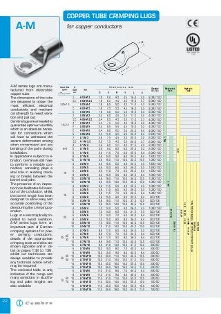
- 1. 22 Hydraulic Tools A-M series lugs are manu- factured from electrolytic copper tube. The dimensions of the tube are designed to obtain the most efficient electrical conductivity and mechani- cal strength to resist vibra- tion and pull out. Cembrelugsareannealedto guarantee optimum ductility which is an absolute neces- sity for connectors which will have to withstand the severe deformation arising when compressed and any bending of the palm during installation. In applications subject to vi- bration, terminals still have to perform a reliable con- nection, annealing plays a vital role in avoiding crack- ing or breaks between the barrel and palm. The presence of an inspec- tion hole facilitates full inser- tion of the conductor, whilst the barrel length has been designed to allow easy and accurate positioning of the dies during the crimping op- eration. Lugs are electrolytically tin- plated to avoid oxidation. A-M series lugs form an important part of Cembre crimping systems for pow- er carrying conductors, details of the appropriate crimping tools and dies are shown opposite and in de- tail on pages 132 to 136, whilst our technicians are always available to provide any technical advice which may be required. The enclosed table is only indicative of the range and many variations in stud fix- ing and palm lengths are also available. COPPER TUBE CRIMPING LUGS for copper conductors 3 A 03-M 3 1,8 6,0 4,5 3,5 16,0 3,2 3,5 A 03-M 3,5 1,8 6,5 4,5 3,5 16,0 3,7 4 A 03-M 4 1,8 6,5 5,0 4,0 17,0 4,3 5 A 03-M 5 1,8 7,5 5,5 4,5 18,0 5,3 6 A 03-M 6 1,8 9,0 6,0 5,0 19,0 6,4 3 A 06-M 3 2,4 6,0 4,5 3,5 17,0 3,2 3,5 A 06-M 3,5 2,4 6,5 4,5 3,5 17,0 3,7 4 A 06-M 4 2,4 7,5 5,0 4,0 18,0 4,3 5 A 06-M 5 2,4 8,5 5,5 4,5 19,0 5,3 6 A 06-M 6 2,4 9,0 6,0 5,0 20,0 6,4 8 A 06-M 8 2,4 12,0 9,0 8,0 26,0 8,4 3 A 1-M 3 3,6 7,5 4,5 3,5 20,5 3,2 3,5 A 1-M 3,5 3,6 7,5 4,5 3,5 20,5 3,7 4 A 1-M 4 3,6 8,0 5,0 4,0 21,5 4,3 5 A 1-M 5 3,6 9,0 6,5 6,0 25,0 5,3 6 A 1-M 6 3,6 11,0 7,0 6,0 25,5 6,4 8 A 1-M 8 3,6 14,0 9,0 8,0 29,5 8,4 10 A 1-M 10 3,6 16,5 11,0 10,0 33,5 10,5 4 A 2-M 4 4,6 10,0 5,0 4,0 22,5 4,3 5 A 2-M 5 4,6 10,0 6,5 6,0 26,0 5,3 6 A 2-M 6 4,6 11,0 7,0 6,0 26,5 6,4 8 A 2-M 8 4,6 15,0 9,0 8,0 30,5 8,4 10 A 2-M 10 4,6 18,0 11,0 10,0 34,5 10,5 12 A 2-M 12 4,6 19,0 14,0 12,0 39,5 13,2 4 A 3-M 4 5,8 11,5 5,0 4,0 25,5 4,3 5 A 3-M 5 5,8 11,5 6,5 6,0 29,0 5,3 6 A 3-M 6 5,8 11,5 7,0 6,0 29,5 6,4 8 A 3-M 8 5,8 15,0 9,0 8,0 33,5 8,4 10 A 3-M 10 5,8 18,0 11,0 10,0 37,5 10,5 12 A 3-M 12 5,8 20,0 14,0 12,0 42,5 13,2 4 A 5-M 4 7,0 14,0 5,0 4,0 28,0 4,3 5 A 5-M 5 7,0 14,0 6,5 6,0 31,5 5,3 6 A 5-M 6 7,0 14,0 7,0 6,0 32,0 6,4 8 A 5-M 8 7,0 15,0 9,0 8,0 36,0 8,4 10 A 5-M 10 7,0 18,0 11,0 10,0 40,0 10,5 12 A 5-M 12 7,0 21,0 14,0 12,0 45,0 13,2 5 A 7-M 5 8,9 17,0 6,5 6,0 34,0 5,3 6 A 7-M 6 8,9 17,0 7,0 6,0 34,5 6,4 8 A 7-M 8 8,9 17,0 9,0 8,0 38,5 8,4 10 A 7-M 10 8,9 19,0 11,0 10,0 42,5 10,5 12 A 7-M 12 8,9 21,0 14,0 12,0 47,5 13,2 6 A 10-M 6 10,0 19,0 8,0 7,0 40,5 6,4 8 A 10-M 8 10,0 19,0 9,0 8,0 42,5 8,4 10 A 10-M 10 10,0 20,0 11,0 10,0 46,5 10,5 12 A 10-M 12 10,0 21,0 14,0 12,0 51,5 13,2 14 A 10-M 14 10,0 25,0 16,0 14,0 55,5 15,0 16 A 10-M 16 10,0 26,0 18,0 16,0 59,5 17,0 6 A 14-M 6 11,3 21,0 8,0 7,0 44,0 6,4 8 A 14-M 8 11,3 21,0 9,0 8,0 46,0 8,4 10 A 14-M 10 11,3 21,0 11,0 10,0 50,0 10,5 12 A 14-M 12 11,3 22,0 14,0 12,0 55,0 13,2 14 A 14-M 14 11,3 25,0 16,0 14,0 59,0 15,0 16 A 14-M 16 11,3 26,0 18,0 16,0 63,0 17,0 5.000/100 5.000/100 5.000/100 5.000/100 5.000/100 4.000/100 4.000/100 4.000/100 4.000/100 4.000/100 2.500/100 2.000/100 2.000/100 2.000/100 2.000/100 2.000/100 1.500/100 1.000/100 1.500/100 1.500/100 1.500/100 1.000/100 1.000/100 1.000/100 1.000/100 1.000/100 1.000/100 500/100 500/100 500/100 1.000/100 500/100 500/100 500/100 500/100 500/100 500/100 500/100 400/100 400/100 300/50 200/50 200/50 200/50 200/50 200/50 200/50 200/50 200/50 200/50 150/50 100/50 100/50 Ø Stud mm Quantity Box/Bag Mechanical Tools Øi B M N L d D i m e n s i o n s m m Ref. 0,25÷1,5 1,5÷2,5 4÷6 10 16 25 25 35 35 35 50 50 50 70 70 HT45-E HT51RH50B51 HT81-URHU81 HT120andtoolsandheadswith130kNcrimpingforce ECW-H3D RHU520 HN1 HN5 TN70SE TN120SE Cond. Size sqmm flexible* low stranded A-M series lugs are manu- factured from electrolytic copper tube. The dimensions of the tube are designed to obtain the most efficient electrical conductivity and mechani- cal strength to resist vibra- tion and pull out. Cembrelugsareannealedto guarantee optimum ductility which is an absolute neces- sity for connectors which will have to withstand the severe deformation arising when compressed and any COPPER TUBE CRIMPING LUGS for copper conductors 3 A 03-M 3 1,8 6,0 4,5 3,5 16,0 3,2 3,5 A 03-M 3,5 1,8 6,5 4,5 3,5 16,0 3,7 4 A 03-M 4 1,8 6,5 5,0 4,0 17,0 4,3 5 A 03-M 5 1,8 7,5 5,5 4,5 18,0 5,3 6 A 03-M 6 1,8 9,0 6,0 5,0 19,0 6,4 3 A 06-M 3 2,4 6,0 4,5 3,5 17,0 3,2 3,5 A 06-M 3,5 2,4 6,5 4,5 3,5 17,0 3,7 4 A 06-M 4 2,4 7,5 5,0 4,0 18,0 4,3 5 A 06-M 5 2,4 8,5 5,5 4,5 19,0 5,3 6 A 06-M 6 2,4 9,0 6,0 5,0 20,0 6,4 8 A 06-M 8 2,4 12,0 9,0 8,0 26,0 8,4 3 A 1-M 3 3,6 7,5 4,5 3,5 20,5 3,2 3,5 A 1-M 3,5 3,6 7,5 4,5 3,5 20,5 3,7 4 A 1-M 4 3,6 8,0 5,0 4,0 21,5 4,3 Ø Stud mm Øi B M N D i m e n s i o n s m m Ref. 0,25÷1,5 40,25÷1,5 4 1,5÷2,5 4 1,5÷2,5 4 5 1,5÷2,5 5 Cond. Size sqmm flexible* low stranded A-M B15
- 2. 23 COPPER TUBE CRIMPING LUGS for copper conductors Hydraulic Tools 6 A 19-M 6 13,5 25,0 8,0 7,0 50,5 6,4 8 A 19-M 8 13,5 25,0 9,0 8,0 52,5 8,4 10 A 19-M 10 13,5 25,0 11,0 10,0 56,5 10,5 12 A 19-M 12 13,5 25,0 14,0 12,0 61,5 13,2 14 A 19-M 14 13,5 25,0 16,0 14,0 65,5 15,0 16 A 19-M 16 13,5 27,0 18,0 16,0 69,5 17,0 20 A 19-M 20 13,5 29,5 22,0 20,0 77,5 21,0 8 A 24-M 8 15,2 28,5 9,0 8,0 54,0 8,4 10 A 24-M 10 15,2 28,5 11,0 10,0 58,0 10,5 12 A 24-M 12 15,2 28,5 14,0 12,0 63,0 13,2 14 A 24-M 14 15,2 28,5 16,0 14,0 67,0 15,0 16 A 24-M 16 15,2 28,5 18,0 16,0 71,0 17,0 20 A 24-M 20 15,2 30,0 22,0 20,0 79,0 21,0 8 A 30-M 8 16,7 31,5 13,0 11,0 69,0 8,4 10 A 30-M 10 16,7 31,5 13,0 11,0 69,0 10,5 12 A 30-M 12 16,7 31,5 16,0 14,0 75,0 13,2 14 A 30-M 14 16,7 31,5 18,0 16,0 79,0 15,0 16 A 30-M 16 16,7 31,5 19,0 17,0 81,0 17,0 20 A 30-M 20 16,7 31,5 22,0 20,0 87,0 21,0 8 A 37-M 8 19,2 35,5 13,0 11,0 76,0 8,4 10 A 37-M 10 19,2 35,5 13,0 11,0 76,0 10,5 12 A 37-M 12 19,2 35,5 16,0 14,0 82,0 13,2 14 A 37-M 14 19,2 35,5 18,0 16,0 86,0 15,0 16 A 37-M 16 19,2 35,5 19,0 17,0 88,0 17,0 20 A 37-M 20 19,2 35,5 22,0 20,0 94,0 21,0 8 A 48-M 8 21,1 39,0 13,0 11,0 82,0 8,4 10 A 48-M 10 21,1 39,0 13,0 11,0 82,0 10,5 12 A 48-M 12 21,1 39,0 16,0 14,0 88,0 13,2 14 A 48-M 14 21,1 39,0 18,0 16,0 92,0 15,0 16 A 48-M 16 21,1 39,0 19,0 17,0 94,0 17,0 20 A 48-M 20 21,1 39,0 22,0 20,0 100,0 21,0 10 A 60-M 10 23,7 44,0 20,0 11,0 96,0 10,5 12 A 60-M 12 23,7 44,0 20,0 14,0 99,0 13,2 14 A 60-M 14 23,7 44,0 22,0 16,0 103,0 15,0 16 A 60-M 16 23,7 44,0 22,0 19,0 106,0 17,0 20 A 60-M 20 23,7 44,0 24,0 23,0 112,0 21,0 12 A 80-M 12 27,0 51,0 22,0 19,0 113,0 13,2 14 A 80-M 14 27,0 51,0 22,0 19,0 113,0 15,0 16 A 80-M 16 27,0 51,0 22,0 19,0 113,0 17,0 20 A 80-M 20 27,0 51,0 24,0 23,0 119,0 21,0 16 A 100-M 16 30,3 56,5 22,0 19,0 117,0 17,0 20 A 100-M 20 30,3 56,5 24,0 23,0 123,0 21,0 16 A 120-M 16 33,4 61,6 22,0 19,0 128,0 17,0 20 A 120-M 20 33,4 61,6 24,0 23,0 134,0 21,0 16 A 160-M 16 38,0 72,0 24,0 19,0 141,0 17,0 20 A 160-M 20 38,0 72,0 24,0 23,0 145,0 21,0 16 A 200-M 16 44,0 80,0 24,0 19,0 158,0 17,0 20 A 200-M 20 44,0 80,0 24,0 23,0 162,0 21,0 100/25 100/25 100/25 100/25 100/25 100/25 100/25 100/25 100/25 100/25 50/25 50/25 50/25 50/25 50/25 50/25 50/25 50/25 50/25 50/25 50/25 50/25 50/25 30/15 30/15 30/15 30/15 30/15 30/15 30/15 30/15 20/10 20/10 20/10 20/10 20/10 15/5 20/5 20/5 20/5 15/5 15/5 12/6 15/5 9/3 9/3 6/2 6/2 Cond. Size sqmm Ø Stud mm Quantity Box/Bag Mechanical Tools Øi B M N L d D i m e n s i o n s m m Ref. 70 95 95 95 120 120 120 150 150 150 185 185 185 240 240 300 240 400 300 500 400 630 500 800 630 1000 800 TN120SE HT45-E HT51RH50B51 HT81-URHU81 HT120andtoolsandheadswith130kNcrimpingforce ECW-H3D RHU520 flexible* low stranded *Actual conductor section may require a larger lug eg for 120mm2 size use A30-... lug. A-M
- 3. 30 Hydraulic Tools ANE-P series terminals are made from electrolytic copper, rolled, tin plated and brazed. The interior of the Nylon insulation sleeve is funnel shaped so as to ensure complete and easy introduction of the conduc- tor strands. In order to achieve the best electrical and mechanical performance it is suggest- ed that they are crimped using dies and tools spe- cifically developed for this purpose by Cembre. NYLON INSULATED PIN TERMINALS 10 ANE 2-P 12 8,0 4,3 14,5 35,1 16 ANE 3-P 14 9,2 5,5 18,0 41,1 25 ANE 5-P 16 11,1 7,0 20,3 45,0 35 ANE 7-P 20 13,6 8,0 24,5 55,0 500/100 500/100 300/100 200/50 Quantity Box/Bag Mechanical Tools Ø B P L D i m e n s i o n s m m Ref. Conductor Size Flexible sqmm TNN120 TNN70 HNN 3 HNN 4 HT51RH50 B51 HT120 andtools andheads with130kN crimpingforce ECW-H3D Hydraulic Tools A-P series pin connectors are designed to terminate conductors into contact blocks. They are manufactured from copper strip, rolled, brazed and tin plated. UNINSULATED PIN CONNECTORS 10 A 2-P 12 4,8 4,3 14,5 23,5 16 A 3-P 14 5,9 5,5 18,0 28,0 25 A 5-P 16 7,0 7,0 20,3 32,0 35 A 7-P 20 8,9 8,0 24,5 39,0 50 A 10-P 25 10,0 9,5 26,0 45,0 70 A 14-P 30 11,5 11,0 31,0 55,0 1.500/100 1.500/100 1.000/100 500/100 250/50 200/50 Quantity Box/Bag Mechanical Tools Øi B P L D i m e n s i o n s m m Ref. Conductor Size sqmm HN5 HN 1 HT45-E HT51RH50B51 HT120 andtools andheads with130kN crimpingforce ECW-H3D ANE-P series terminals are made from electrolytic NYLON INSULATED PIN TERMINALS D i m e n s i o n s m m Ref. Conductor Size Flexible ANE-P UNINSULATED PIN CONNECTORS A-P series pin connectors are designed to terminate D i m e n s i o n s m m Ref. Conductor Size A-P B15 TN120SE TN70SE