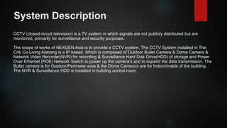
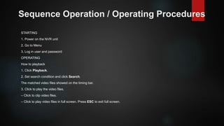
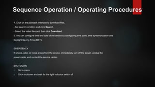
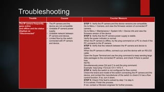
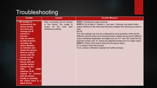
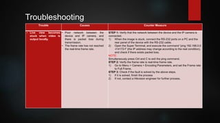
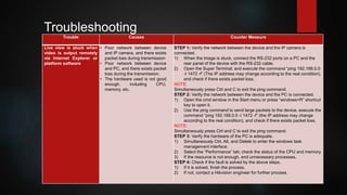
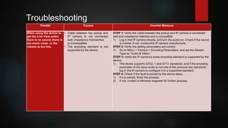
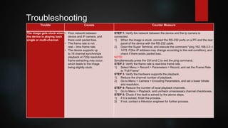
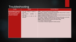
CCTV SYSTEM
THE CRIB CO-LIVING ALABANG
CCTV TRAINING MODULE
 Introduction
 Objectives
 System Description
 Sequence of Operation / Operating Procedures
(Starting, Operating, Emergency, & Shutdown)
 Safety Practices
 Testing / Troubleshooting
 Preventive Maintenance
Introduction
A Surveillance or Closed Circuit Television (CCTV) System is made up of one or many security cameras
that capture and send video to a Network Video Recorder (NVR) or a cloud-based server, which records
the video footage and presents them on a monitor or other connected device.
Objectives
The main objectives of CCTV System in The Crib Co-Living Alabang is to maximize the security
through video surveillance in the areas.
System Description
CCTV (closed-circuit television) is a TV system in which signals are not publicly distributed but are
monitored, primarily for surveillance and security purposes.
The scope of works of NEXGEN Asia is to provide a CCTV system, The CCTV System installed in The
Crib Co-Living Alabang is a IP based. Which is composed of Outdoor Bullet Camera & Dome Camera &
Network Video Recorder(NVR) for recording & Surveillance Hard Disk Drive(HDD) of storage and Power
Over Ethernet (POE) Network Switch to power up the camera’s and to expand the data transmission. The
Bullet camera is for Outdoor/Perimeter area & the Dome Camera’s are for Indoor/Inside of the building.
The NVR & Surveillance HDD is installed in building control room.
Sequence Operation / Operating Procedures
STARTING
1. Power on the NVR unit
2. Go to Menu
3. Log in user and password
OPERATING
How to playback
1. Click Playback.
2. Set search condition and click Search.
The matched video files showed on the timing bar.
3. Click to play the video files.
– Click to clip video files.
– Click to play video files in full screen. Press ESC to exit full screen.
Sequence Operation / Operating Procedures
4. Click on the playback interface to download files.
- Set search condition and click Search.
- Select the video files and then click Download.
5. You can configure time and date of the device by configuring time zone, time synchronization and
Daylight Saving Time (DST).
EMERGENCY
If smoke, odor, or noise arises from the device, immediately turn off the power, unplug the
power cable, and contact the service center.
SHUTDOWN
1. Go to menu
2. Click shutdown and wait for the light indicator switch off
Please watch the Configuration,
Basic CCTV System Operation &
Playback & download
Safety Practices
for Camera
These instructions are intended to ensure that user can use the product correctly to avoid danger or property loss.
Transportation
● Keep the device in original or similar packaging while transporting it.
Power Supply
● Make sure the plug is properly connected to the power socket.
● DO NOT connect multiple devices to one power adapter, to avoid over-heating or fire hazards caused by overload.
System Security
● The installer and user are responsible for password and security configuration and its settings.
Battery
● Improper use or replacement of the battery may result in explosion hazard.
● Replace with the same or equivalent type only. Dispose of used batteries in conformance with the local codes.
Using Environment
● Make sure the running environment meets the requirement of the device. The operating temperature shall be -30°C to 60°C (-22°F to 140°F), and the operating
humidity shall be 95% or less, no condensing.
● Do not expose the device to high electromagnetic radiation or dusty environments.
● For indoor-only device, place it in a dry and well-ventilated environment.
● Do not aim the lens at the sun or any other bright light.
Safety Practices
for NVR
● Proper configuration of all passwords and other security settings is the
responsibility of the installer and/or end-user.
● Firmly connect the plug to the power socket. Do not connect several devices
to one power adapter. Power off the device before connecting and disconnecting
accessories and peripherals.
● Shock hazard! Disconnect all power sources before maintenance.
● The equipment must be connected to an earthed mains socket-outlet.
● The socket-outlet shall be installed near the equipment and shall be easily
accessible.
● indicates hazardous live and the external wiring connected to the terminals
requires installation by an instructed person.
● Never place the equipment in an unstable location. The equipment may fall,
causing serious personal injury or death.
● Input voltage should meet the SELV (Safety Extra Low Voltage) and the LPS
(Limited Power Source) according to the IEC62368.
● High touch current! Connect to earth before connecting to the power supply.
● If smoke, odor or noise rise from the device, turn off the power at once and
unplug the power cable, and then please contact the service center.
● Use the device in conjunction with an UPS, and use factory recommended
HDD if possible.
● This product contains a coin/button cell battery. If the battery is swallowed, it
can cause severe
internal burns in just 2 hours and can lead to death.
● This equipment is not suitable for use in locations where children are likely to
be present.
● CAUTION: Risk of explosion if the battery is replaced by an incorrect type.
● Improper replacement of the battery with an incorrect type may defeat a
safeguard (for example, in the case of some lithium battery types).
● Do not dispose of the battery into fire or a hot oven, or mechanically crush or
cut the battery,
which may result in an explosion.
● Do not leave the battery in an extremely high temperature surrounding
environment, which
may result in an explosion or the leakage of flammable liquid or gas.
● Do not subject the battery to extremely low air pressure, which may result in
an explosion or
the leakage of flammable liquid or gas.
● Dispose of used batteries according to the instructions.
● Keep body parts away from fan blades and motors. Disconnect the power
source during
servicing.
● Keep body parts away from motors. Disconnect the power source during
servicing.
Testing
Once the interconnection is understood and tested, commissioning can be proceeded. Commissioning
is a detailed process and would require comprehensive but specific checklists for each item, in order to
have record of tests results for future. Commissioning of CCTV system primarily comprise of following:
1. Visual Inspections
2. Power ON Checks
3. Functional Test of field equipment
4. Test Completion
Visual inspection - is conducted for all cameras, junction boxes, major cabling locations and central
cabinet. Cameras and Junction boxes are checked for any apparent mechanical damage, correct tag
number, exact location and verification of correct termination as per design. Major cabling locations are
to be checked visually for any scratch, over bending, free hanging (if the cable is not designed for such
free hang), overstretching and correct size of glands. In central cabinet it is checked that all cabinet
units are present and arranged in the enclosure as per the cabinet arrangement drawing, all
connections (cat6/utp’s, and paired) are terminated properly and correctly as per the internal wiring
diagram of cabinet.
Testing
Power ON check - is to ensure the System Hardware is functionally correct in all respect
like redundancy, alarm indication and voltage segregation after Power on. Before turning ON the power
it is tested using calibrated voltmeter at the input terminals of incoming breaker that rated voltage are
available within tolerable range. The first half of the power ON check is cabinet main power turn ON
test, following are the steps for this test:
1. Switch ‘ON’ main breaker (usually it is Miniature Circuit Beaker, check voltage on its output
terminals.
2. Switch ‘ON’ individual and check voltage on its output terminals, ensure the respective output
devices are ‘ON’ such as NVR, CCTV power supply, network switch, access points and Power
Supply Unit (PSU) driving some equipment’s in cabinets; by checking the ON indication (LED)
where available.
3. Make sure Power is normal during this phase. If so then all connections to be verified for any
short circuit and ground fault as well as the incoming supply to be confirm within tolerable range.
Testing
Functionality Test:
Functional tests of cameras are usually performed from control room's operator workstation however
can be tested using CCTV service monitor (a handheld device) at the junction box or at central cabinet.
Result from each camera is documented in separate checklist. Following checks are confirmed while
performing the functional test of camera:
1. Verify focus whether it is auto focus or adjusted for near and far objects.
2. Check recording from HDD (hard disk drive)
3. Check NVR settings (eg: dates,time,displays etc.)
4. Check PC work station functionality.
5. Check TV monitors for clarity, image & display settings.
6. Check auto iris and manual override working correctly. (Manual override is not applicable in
Fixed cameras)
7. Check area coverage (Only for dome cameras)
8. Check Infrared (IR) function.
9. Confirm resolution is clear.
10. Check device labels and tagging including cable connection. (for maintenance use)
All Test Completion report to be generated at the end of tests attached with check lists for all tests. A
copy of the report to be keep with end user for future expansion, modification or maintenance.
Troubleshooting
Trouble Causes Counter Measure
No image displayed on the
monitor after starting up
normally.
• No VGA or HDMI connections STEP 1: Verify the device is connected to the monitor via HDMI or VGA
cable.
STEP 2: If not, connect the device to the monitor and reboot.
STEP 3: Verify the connection cable is good.
STEP 4: If there is still no image displayed on the monitor after
rebooting, check if the connection cable is good.
STEP 5: Verify Input mode of the monitor is correct.
STEP 6: Check that the monitor input mode matches the output mode of the
device (e.g., if the device’s output mode is HDMI, then the monitor input mode
must be HDMI). If not, modify the monitor’s input mode.
STEP 7: Check if the fault is solved by step 1 to step 3.
STEP 8: If it is solved, Finish the process.
STEP 9: If not, contact a Hikvision engineer for further process.
Trouble Causes Counter Measure
There is an audible
warning sound “Di-Di-Di-
DiDi” after a new device
starts up
• No HDD is installed in the
devices
• The installed HDD has not been
initialized
• The installed HDD is not
compatible with the device
or is broken
STEP 1: Verify at least one HDD is installed in the device. If not, install a
compatible HDD.
Note:
Refer to the Quick Start Guide for the HDD is initialized.
- If you don’t want to install an HDD, go to Menu > System > Event >
Normal > Event > Exception, and uncheck the “HDD Error” Audible
Warning checkbox.
STEP 2: Verify the HDD is initialized.
1) Go to Menu > Storage > Storage Device.
2) If the HDD status is “Uninitialized” check the checkbox of
the corresponding HDD and Click it
STEP 3: Verify the HDD is detected and is in good condition.
1) Select Menu > Storage > Storage Device.
2) If the HDD is not detected or the status is “Abnormal,” replace the
dedicated HDD according to the requirement.
STEP 4: Check if the fault is solved by step 1 to step 3.
1) If it is solved, Finish the process.
Troubleshooting
Trouble Causes Counter Measure
The status of the added
IP camera displays as
“Disconnected” when
it is connected through
Private protocol.
Select Menu > Camera
> IP camera to get the
camera status
• Network failure, and the
device and IP camera
• The configured parameters
are incorrect when adding
the IP camera – insufficient
bandwidth
STEP 1: Verify the network is connected.
Connect the device and PC with the RS-232 cable.
Open the Super Terminal software, and execute the ping command. Input
“ping IP”
(e.g., ping 172.6.22.131).
NOTE:
Simultaneously press Ctrl and C to exit the ping command.
If there exists return information and the time value is small, the network is
normal.
STEP 2: Verify the configuration Parameters are correct.
Go to Menu > Camera.
Verify the parameters are the same as those of connected IP devices,
including IP address, protocol, management port, username, and
password.
STEP 3: Verify the bandwidth is enough.
Go to Menu > Maintenance > Net Detect > Network Stat.
Check the usage of the access bandwidth, and see if the total bandwidth
has reached its limit.
STEP 4: If not, contact a Hikvision engineer for further process.
Troubleshooting
Troubleshooting
Trouble Causes Counter Measure
The IP camera frequently
goes online
and offline and the status
displays as
“Disconnected”
• The IP camera and the
device are not compatible
• Unstable IP camera power
supply.
• Unstable network between
IP camera and device.
• Limited flow by the switch
connected with IP camera
and device.
STEP 1: Verify the IP camera and the device versions are compatible.
Go to Menu > Camera, and view the firmware version of connected IP
camera.
Go to Menu > Maintenance > System Info > Device info and view the
firmware version of the device
STEP 2: Verify that the IP camera power supply is stable.
Verify the power indicator is normal.
When the IP camera is offline, try the ping command on a PC to check if the
PC connects to the IP camera.
STEP 3: Verify that the network between the IP camera and device is
stable.
When the IP camera is offline, connect a pc and the device with an RS-232
cable
Open the Super Terminal and use the ping command to keep sending large
data packages to the connected IP camera, and check if there is packet
loss.
NOTE:
Simultaneously press Ctrl and C to exit the ping command.
Example: Input ping 172.6.22.131-I 1472 -f.
STEP 4: Verify the switch is not configured for flow control.
Check the brand and model of the switch connecting the IP camera and the
device, and contact the manufacturer of the switch to check if it has a flow
control function. If so, turn it down.
STEP 5: Check if the fault is solved by step 1 to step 4.
If it is solved. Finish the process.
If not, contact a Hikvision engineer for further process..
Trouble Causes Counter Measure
• No monitor is
connected to the
device locally,
and when you
manage the IP
camera to
connect
with the device
by Web browser
remotely, the
status displays
as interface and
reboot the device,
there is a black
screen with the
mouse cursor.
• Connect the
device with the
monitor before
startup via the
VGA or HDMI
interface, of IP
camera to connect
with the device
locally or remotely
the status there is a
black screen
• After connecting the IP camera
to the device, the image is
output via the main spot
interface by default.
STEP 1: Enable the output channel.
STEP 2: Go to Menu > System > Live view > General, and select video
output interface in the drop-down list and configure the window you want to
view.
NOTE:
The view settings can only be configured by local operation of the device.
Different camera orders and window-division modes can be set for different
output interfaces separately, and digits such as “D1” and “D2” stand for the
channel number, and “X” means the selected window has no image output.
STEP 3: Check if the fault is solved by the above steps.
If it is solved, finish the process.
If not, contact a Hikvision engineer for further process.
Troubleshooting
Trouble Causes Counter Measure
• Live view becomes
stuck when video is
output locally.
• Poor network between the
device and IP camera, and
there is packet loss during
transmission.
• The frame rate has not reached
the real-time frame rate.
STEP 1: Verify that the network between the device and the IP camera is
connected.
1) When the image is stuck, connect the RS-232 ports on a PC and the
rear panel of the device with the RS-232 cable.
2) Open the Super Terminal, and execute the command “ping 192.168.0.0
-I14172-f” (the IP address may change according to the real condition),
and check if there exists packet loss.
NOTE:
Simultaneously press Ctrl and C to exit the ping command.
STEP 2: Verify the frame rate is real-time frame rate.
1) Go to Menu > Camera > Encoding Parameters, and set the Frame rate
to Full Frame.
STEP 3: Check if the fault is solved by the above steps.
1) If it is solved, finish the process
2) If not, contact a Hikvision engineer for further process.
Troubleshooting
Trouble Causes Counter Measure
Live view is stuck when
video is output remotely
via Internet Explorer or
platform software
• Poor network between device
and IP camera, and there exists
packet loss during transmission
• Poor network between device
and PC, and there exists packet
loss during the transmission.
• The hardware used is not good
enough, including CPU,
memory, etc.
STEP 1: Verify the network between the device and the IP camera is
connected.
1) When the image is stuck, connect the RS-232 ports on a PC and the
rear panel of the device with the RS-232 cable.
2) Open the Super Terminal, and execute the command “ping 192.168.0.0
-I 1472 -f” (The IP address may change according to the real condition),
and check if there exists packet loss.
NOTE:
Simultaneously press Ctrl and C to exit the ping command.
STEP 2: Verify the network between the device and the PC is connected.
1) Open the cmd window in the Start menu or press “windows+R” shortcut
key to open it.
2) Use the ping command to send large packets to the device, execute the
command “ping 192.168.0.0 -I 1472 -f” (the IP address may change
according to the real condition), and check if there exists packet loss.
NOTE:
Simultaneously press Ctrl and C to exit the ping command.
STEP 3: Verify the hardware of the PC is adequate.
1) Simultaneously Ctrl, Alt, and Delete to enter the windows task
management interface.
2) Select the “Performance” tab; check the status of the CPU and memory.
3) If the resource is not enough, end unnecessary processes.
STEP 4: Check if the fault is solved by the above steps.
1) If it is solved, finish the process.
2) If not, contact a Hikvision engineer for further process.
Troubleshooting
Trouble Causes Counter Measure
When using the device to
get the Live View audio,
there is no sound, there is
too much noise, or the
volume is too low.
• Cable between the pickup and
IP camera is not connected
well; impedance mismatches
or incompatible
• The encoding standard is not
supported by the device.
STEP 1: Verify the cable between the pickup and IP camera is connected
well and impedance matches and is compatible.
1) Log in the IP camera directly, and turn the audio on. Check if the sound
is normal. If not, contact the IP camera manufacturer.
STEP 2: Verify the setting parameters are correct
1) Go to Menu > Camera > Encoding Parameters, and set the Stream
Type as “Audio & Video.”
STEP 3: Verify the IP camera’s audio encoding standard is supported by the
device.
1) The device supports G722. 1 and G711 standards, and if the encoding
parameter of the input audio is not one of the previous two standards,
log in the IP camera to configure it to a supported standard.
STEP 4: Check if the fault is solved by the above steps.
1) If it is solved, finish the process.
2) If not, contact a Hikvision engineer for further process.
Troubleshooting
Trouble Causes Counter Measure
The image gets stuck when
the device is playing back
single or multi-channel.
• Poor network between
device and IP camera, and
there exist packet loss.
• The frame rate is not
real – time frame rate.
• The device supports up
to 16 channel synchronize
playback at 720p resolution
frame extracting may occur,
which leads to the image
being slightly stuck.
STEP 1: Verify the network between the device and the Ip camera is
connected.
1) When the image is stuck, connect the RS-232 ports on a PC and the rear
panel of the device with the RS-232 cable.
2) Open the Super Terminal, and execute the command “ping 192.168.0.0 -I
1472 -f”(the IP address may change according to the real condition), and
check if there exists packet loss.
NOTE:
Simultaneously press the Ctrl and C to exit the ping command.
STEP 2: Verify the frame rate is real-time frame rate.
1) Select Menu > Record > Parameters > Record, and set the Frame Rate
to “Full Frame”
STEP 3: Verify the hardware supports the playback.
1) Reduce the channel number of playback.
2) Go to Menu > Camera > Encoding Parameters, and set a lower bitrate
and resolution.
STEP 4: Reduce the number of local playback channels.
1) Go to Menu > Playback, and uncheck unnecessary channel checkboxes.
STEP 5: Check if the fault is solved by the above steps.
1) If it is solved, finish the process.
2) If not, contact a Hikvision engineer for further process.
Troubleshooting
Trouble Causes Counter Measure
No record file is found in
device’s local HDD, and a
“No record file found”
prompt is displayed.
• The time setting of system is
incorrect.
• The search condition is
incorrect.
• The HDD is in error or not
detected.
STEP 1: Verify the system time setting is correct.
Go to Menu > System > General and verify that the “Device Time” is correct.
STEP 2: Verify the search condition is correct.
Go to the playback interface, and verify that the channel and time are correct.
STEP 3: Verify that the HDD status is normal.
Go to Menu > Storage > Storage Device to view the HDD status, and verify
that the HDD is detected and can be read and written normally.
STEP 4: Check if the fault is solved by the above steps.
If it is solved, Finish the process.
If not contact a Hikvision engineer for further process.
Troubleshooting
Preventive Maintenance
CCTV Camera
Preventive Maintenance
Wiring & Cabling
Preventive Maintenance
Control Equipment
That’s all for CCTV System! Thank you!
Prepared by: RM.Tolentino

CCTV & TRAINING MODULE PRESENTATION.pptx

  • 1.
    CCTV SYSTEM THE CRIBCO-LIVING ALABANG
  • 2.
    CCTV TRAINING MODULE Introduction  Objectives  System Description  Sequence of Operation / Operating Procedures (Starting, Operating, Emergency, & Shutdown)  Safety Practices  Testing / Troubleshooting  Preventive Maintenance
  • 3.
    Introduction A Surveillance orClosed Circuit Television (CCTV) System is made up of one or many security cameras that capture and send video to a Network Video Recorder (NVR) or a cloud-based server, which records the video footage and presents them on a monitor or other connected device.
  • 4.
    Objectives The main objectivesof CCTV System in The Crib Co-Living Alabang is to maximize the security through video surveillance in the areas.
  • 5.
    System Description CCTV (closed-circuittelevision) is a TV system in which signals are not publicly distributed but are monitored, primarily for surveillance and security purposes. The scope of works of NEXGEN Asia is to provide a CCTV system, The CCTV System installed in The Crib Co-Living Alabang is a IP based. Which is composed of Outdoor Bullet Camera & Dome Camera & Network Video Recorder(NVR) for recording & Surveillance Hard Disk Drive(HDD) of storage and Power Over Ethernet (POE) Network Switch to power up the camera’s and to expand the data transmission. The Bullet camera is for Outdoor/Perimeter area & the Dome Camera’s are for Indoor/Inside of the building. The NVR & Surveillance HDD is installed in building control room.
  • 6.
    Sequence Operation /Operating Procedures STARTING 1. Power on the NVR unit 2. Go to Menu 3. Log in user and password OPERATING How to playback 1. Click Playback. 2. Set search condition and click Search. The matched video files showed on the timing bar. 3. Click to play the video files. – Click to clip video files. – Click to play video files in full screen. Press ESC to exit full screen.
  • 7.
    Sequence Operation /Operating Procedures 4. Click on the playback interface to download files. - Set search condition and click Search. - Select the video files and then click Download. 5. You can configure time and date of the device by configuring time zone, time synchronization and Daylight Saving Time (DST). EMERGENCY If smoke, odor, or noise arises from the device, immediately turn off the power, unplug the power cable, and contact the service center. SHUTDOWN 1. Go to menu 2. Click shutdown and wait for the light indicator switch off
  • 8.
    Please watch theConfiguration, Basic CCTV System Operation & Playback & download
  • 12.
    Safety Practices for Camera Theseinstructions are intended to ensure that user can use the product correctly to avoid danger or property loss. Transportation ● Keep the device in original or similar packaging while transporting it. Power Supply ● Make sure the plug is properly connected to the power socket. ● DO NOT connect multiple devices to one power adapter, to avoid over-heating or fire hazards caused by overload. System Security ● The installer and user are responsible for password and security configuration and its settings. Battery ● Improper use or replacement of the battery may result in explosion hazard. ● Replace with the same or equivalent type only. Dispose of used batteries in conformance with the local codes. Using Environment ● Make sure the running environment meets the requirement of the device. The operating temperature shall be -30°C to 60°C (-22°F to 140°F), and the operating humidity shall be 95% or less, no condensing. ● Do not expose the device to high electromagnetic radiation or dusty environments. ● For indoor-only device, place it in a dry and well-ventilated environment. ● Do not aim the lens at the sun or any other bright light.
  • 13.
    Safety Practices for NVR ●Proper configuration of all passwords and other security settings is the responsibility of the installer and/or end-user. ● Firmly connect the plug to the power socket. Do not connect several devices to one power adapter. Power off the device before connecting and disconnecting accessories and peripherals. ● Shock hazard! Disconnect all power sources before maintenance. ● The equipment must be connected to an earthed mains socket-outlet. ● The socket-outlet shall be installed near the equipment and shall be easily accessible. ● indicates hazardous live and the external wiring connected to the terminals requires installation by an instructed person. ● Never place the equipment in an unstable location. The equipment may fall, causing serious personal injury or death. ● Input voltage should meet the SELV (Safety Extra Low Voltage) and the LPS (Limited Power Source) according to the IEC62368. ● High touch current! Connect to earth before connecting to the power supply. ● If smoke, odor or noise rise from the device, turn off the power at once and unplug the power cable, and then please contact the service center. ● Use the device in conjunction with an UPS, and use factory recommended HDD if possible. ● This product contains a coin/button cell battery. If the battery is swallowed, it can cause severe internal burns in just 2 hours and can lead to death. ● This equipment is not suitable for use in locations where children are likely to be present. ● CAUTION: Risk of explosion if the battery is replaced by an incorrect type. ● Improper replacement of the battery with an incorrect type may defeat a safeguard (for example, in the case of some lithium battery types). ● Do not dispose of the battery into fire or a hot oven, or mechanically crush or cut the battery, which may result in an explosion. ● Do not leave the battery in an extremely high temperature surrounding environment, which may result in an explosion or the leakage of flammable liquid or gas. ● Do not subject the battery to extremely low air pressure, which may result in an explosion or the leakage of flammable liquid or gas. ● Dispose of used batteries according to the instructions. ● Keep body parts away from fan blades and motors. Disconnect the power source during servicing. ● Keep body parts away from motors. Disconnect the power source during servicing.
  • 14.
    Testing Once the interconnectionis understood and tested, commissioning can be proceeded. Commissioning is a detailed process and would require comprehensive but specific checklists for each item, in order to have record of tests results for future. Commissioning of CCTV system primarily comprise of following: 1. Visual Inspections 2. Power ON Checks 3. Functional Test of field equipment 4. Test Completion Visual inspection - is conducted for all cameras, junction boxes, major cabling locations and central cabinet. Cameras and Junction boxes are checked for any apparent mechanical damage, correct tag number, exact location and verification of correct termination as per design. Major cabling locations are to be checked visually for any scratch, over bending, free hanging (if the cable is not designed for such free hang), overstretching and correct size of glands. In central cabinet it is checked that all cabinet units are present and arranged in the enclosure as per the cabinet arrangement drawing, all connections (cat6/utp’s, and paired) are terminated properly and correctly as per the internal wiring diagram of cabinet.
  • 15.
    Testing Power ON check- is to ensure the System Hardware is functionally correct in all respect like redundancy, alarm indication and voltage segregation after Power on. Before turning ON the power it is tested using calibrated voltmeter at the input terminals of incoming breaker that rated voltage are available within tolerable range. The first half of the power ON check is cabinet main power turn ON test, following are the steps for this test: 1. Switch ‘ON’ main breaker (usually it is Miniature Circuit Beaker, check voltage on its output terminals. 2. Switch ‘ON’ individual and check voltage on its output terminals, ensure the respective output devices are ‘ON’ such as NVR, CCTV power supply, network switch, access points and Power Supply Unit (PSU) driving some equipment’s in cabinets; by checking the ON indication (LED) where available. 3. Make sure Power is normal during this phase. If so then all connections to be verified for any short circuit and ground fault as well as the incoming supply to be confirm within tolerable range.
  • 16.
    Testing Functionality Test: Functional testsof cameras are usually performed from control room's operator workstation however can be tested using CCTV service monitor (a handheld device) at the junction box or at central cabinet. Result from each camera is documented in separate checklist. Following checks are confirmed while performing the functional test of camera: 1. Verify focus whether it is auto focus or adjusted for near and far objects. 2. Check recording from HDD (hard disk drive) 3. Check NVR settings (eg: dates,time,displays etc.) 4. Check PC work station functionality. 5. Check TV monitors for clarity, image & display settings. 6. Check auto iris and manual override working correctly. (Manual override is not applicable in Fixed cameras) 7. Check area coverage (Only for dome cameras) 8. Check Infrared (IR) function. 9. Confirm resolution is clear. 10. Check device labels and tagging including cable connection. (for maintenance use) All Test Completion report to be generated at the end of tests attached with check lists for all tests. A copy of the report to be keep with end user for future expansion, modification or maintenance.
  • 17.
    Troubleshooting Trouble Causes CounterMeasure No image displayed on the monitor after starting up normally. • No VGA or HDMI connections STEP 1: Verify the device is connected to the monitor via HDMI or VGA cable. STEP 2: If not, connect the device to the monitor and reboot. STEP 3: Verify the connection cable is good. STEP 4: If there is still no image displayed on the monitor after rebooting, check if the connection cable is good. STEP 5: Verify Input mode of the monitor is correct. STEP 6: Check that the monitor input mode matches the output mode of the device (e.g., if the device’s output mode is HDMI, then the monitor input mode must be HDMI). If not, modify the monitor’s input mode. STEP 7: Check if the fault is solved by step 1 to step 3. STEP 8: If it is solved, Finish the process. STEP 9: If not, contact a Hikvision engineer for further process.
  • 18.
    Trouble Causes CounterMeasure There is an audible warning sound “Di-Di-Di- DiDi” after a new device starts up • No HDD is installed in the devices • The installed HDD has not been initialized • The installed HDD is not compatible with the device or is broken STEP 1: Verify at least one HDD is installed in the device. If not, install a compatible HDD. Note: Refer to the Quick Start Guide for the HDD is initialized. - If you don’t want to install an HDD, go to Menu > System > Event > Normal > Event > Exception, and uncheck the “HDD Error” Audible Warning checkbox. STEP 2: Verify the HDD is initialized. 1) Go to Menu > Storage > Storage Device. 2) If the HDD status is “Uninitialized” check the checkbox of the corresponding HDD and Click it STEP 3: Verify the HDD is detected and is in good condition. 1) Select Menu > Storage > Storage Device. 2) If the HDD is not detected or the status is “Abnormal,” replace the dedicated HDD according to the requirement. STEP 4: Check if the fault is solved by step 1 to step 3. 1) If it is solved, Finish the process. Troubleshooting
  • 19.
    Trouble Causes CounterMeasure The status of the added IP camera displays as “Disconnected” when it is connected through Private protocol. Select Menu > Camera > IP camera to get the camera status • Network failure, and the device and IP camera • The configured parameters are incorrect when adding the IP camera – insufficient bandwidth STEP 1: Verify the network is connected. Connect the device and PC with the RS-232 cable. Open the Super Terminal software, and execute the ping command. Input “ping IP” (e.g., ping 172.6.22.131). NOTE: Simultaneously press Ctrl and C to exit the ping command. If there exists return information and the time value is small, the network is normal. STEP 2: Verify the configuration Parameters are correct. Go to Menu > Camera. Verify the parameters are the same as those of connected IP devices, including IP address, protocol, management port, username, and password. STEP 3: Verify the bandwidth is enough. Go to Menu > Maintenance > Net Detect > Network Stat. Check the usage of the access bandwidth, and see if the total bandwidth has reached its limit. STEP 4: If not, contact a Hikvision engineer for further process. Troubleshooting
  • 20.
    Troubleshooting Trouble Causes CounterMeasure The IP camera frequently goes online and offline and the status displays as “Disconnected” • The IP camera and the device are not compatible • Unstable IP camera power supply. • Unstable network between IP camera and device. • Limited flow by the switch connected with IP camera and device. STEP 1: Verify the IP camera and the device versions are compatible. Go to Menu > Camera, and view the firmware version of connected IP camera. Go to Menu > Maintenance > System Info > Device info and view the firmware version of the device STEP 2: Verify that the IP camera power supply is stable. Verify the power indicator is normal. When the IP camera is offline, try the ping command on a PC to check if the PC connects to the IP camera. STEP 3: Verify that the network between the IP camera and device is stable. When the IP camera is offline, connect a pc and the device with an RS-232 cable Open the Super Terminal and use the ping command to keep sending large data packages to the connected IP camera, and check if there is packet loss. NOTE: Simultaneously press Ctrl and C to exit the ping command. Example: Input ping 172.6.22.131-I 1472 -f. STEP 4: Verify the switch is not configured for flow control. Check the brand and model of the switch connecting the IP camera and the device, and contact the manufacturer of the switch to check if it has a flow control function. If so, turn it down. STEP 5: Check if the fault is solved by step 1 to step 4. If it is solved. Finish the process. If not, contact a Hikvision engineer for further process..
  • 21.
    Trouble Causes CounterMeasure • No monitor is connected to the device locally, and when you manage the IP camera to connect with the device by Web browser remotely, the status displays as interface and reboot the device, there is a black screen with the mouse cursor. • Connect the device with the monitor before startup via the VGA or HDMI interface, of IP camera to connect with the device locally or remotely the status there is a black screen • After connecting the IP camera to the device, the image is output via the main spot interface by default. STEP 1: Enable the output channel. STEP 2: Go to Menu > System > Live view > General, and select video output interface in the drop-down list and configure the window you want to view. NOTE: The view settings can only be configured by local operation of the device. Different camera orders and window-division modes can be set for different output interfaces separately, and digits such as “D1” and “D2” stand for the channel number, and “X” means the selected window has no image output. STEP 3: Check if the fault is solved by the above steps. If it is solved, finish the process. If not, contact a Hikvision engineer for further process. Troubleshooting
  • 22.
    Trouble Causes CounterMeasure • Live view becomes stuck when video is output locally. • Poor network between the device and IP camera, and there is packet loss during transmission. • The frame rate has not reached the real-time frame rate. STEP 1: Verify that the network between the device and the IP camera is connected. 1) When the image is stuck, connect the RS-232 ports on a PC and the rear panel of the device with the RS-232 cable. 2) Open the Super Terminal, and execute the command “ping 192.168.0.0 -I14172-f” (the IP address may change according to the real condition), and check if there exists packet loss. NOTE: Simultaneously press Ctrl and C to exit the ping command. STEP 2: Verify the frame rate is real-time frame rate. 1) Go to Menu > Camera > Encoding Parameters, and set the Frame rate to Full Frame. STEP 3: Check if the fault is solved by the above steps. 1) If it is solved, finish the process 2) If not, contact a Hikvision engineer for further process. Troubleshooting
  • 23.
    Trouble Causes CounterMeasure Live view is stuck when video is output remotely via Internet Explorer or platform software • Poor network between device and IP camera, and there exists packet loss during transmission • Poor network between device and PC, and there exists packet loss during the transmission. • The hardware used is not good enough, including CPU, memory, etc. STEP 1: Verify the network between the device and the IP camera is connected. 1) When the image is stuck, connect the RS-232 ports on a PC and the rear panel of the device with the RS-232 cable. 2) Open the Super Terminal, and execute the command “ping 192.168.0.0 -I 1472 -f” (The IP address may change according to the real condition), and check if there exists packet loss. NOTE: Simultaneously press Ctrl and C to exit the ping command. STEP 2: Verify the network between the device and the PC is connected. 1) Open the cmd window in the Start menu or press “windows+R” shortcut key to open it. 2) Use the ping command to send large packets to the device, execute the command “ping 192.168.0.0 -I 1472 -f” (the IP address may change according to the real condition), and check if there exists packet loss. NOTE: Simultaneously press Ctrl and C to exit the ping command. STEP 3: Verify the hardware of the PC is adequate. 1) Simultaneously Ctrl, Alt, and Delete to enter the windows task management interface. 2) Select the “Performance” tab; check the status of the CPU and memory. 3) If the resource is not enough, end unnecessary processes. STEP 4: Check if the fault is solved by the above steps. 1) If it is solved, finish the process. 2) If not, contact a Hikvision engineer for further process. Troubleshooting
  • 24.
    Trouble Causes CounterMeasure When using the device to get the Live View audio, there is no sound, there is too much noise, or the volume is too low. • Cable between the pickup and IP camera is not connected well; impedance mismatches or incompatible • The encoding standard is not supported by the device. STEP 1: Verify the cable between the pickup and IP camera is connected well and impedance matches and is compatible. 1) Log in the IP camera directly, and turn the audio on. Check if the sound is normal. If not, contact the IP camera manufacturer. STEP 2: Verify the setting parameters are correct 1) Go to Menu > Camera > Encoding Parameters, and set the Stream Type as “Audio & Video.” STEP 3: Verify the IP camera’s audio encoding standard is supported by the device. 1) The device supports G722. 1 and G711 standards, and if the encoding parameter of the input audio is not one of the previous two standards, log in the IP camera to configure it to a supported standard. STEP 4: Check if the fault is solved by the above steps. 1) If it is solved, finish the process. 2) If not, contact a Hikvision engineer for further process. Troubleshooting
  • 25.
    Trouble Causes CounterMeasure The image gets stuck when the device is playing back single or multi-channel. • Poor network between device and IP camera, and there exist packet loss. • The frame rate is not real – time frame rate. • The device supports up to 16 channel synchronize playback at 720p resolution frame extracting may occur, which leads to the image being slightly stuck. STEP 1: Verify the network between the device and the Ip camera is connected. 1) When the image is stuck, connect the RS-232 ports on a PC and the rear panel of the device with the RS-232 cable. 2) Open the Super Terminal, and execute the command “ping 192.168.0.0 -I 1472 -f”(the IP address may change according to the real condition), and check if there exists packet loss. NOTE: Simultaneously press the Ctrl and C to exit the ping command. STEP 2: Verify the frame rate is real-time frame rate. 1) Select Menu > Record > Parameters > Record, and set the Frame Rate to “Full Frame” STEP 3: Verify the hardware supports the playback. 1) Reduce the channel number of playback. 2) Go to Menu > Camera > Encoding Parameters, and set a lower bitrate and resolution. STEP 4: Reduce the number of local playback channels. 1) Go to Menu > Playback, and uncheck unnecessary channel checkboxes. STEP 5: Check if the fault is solved by the above steps. 1) If it is solved, finish the process. 2) If not, contact a Hikvision engineer for further process. Troubleshooting
  • 26.
    Trouble Causes CounterMeasure No record file is found in device’s local HDD, and a “No record file found” prompt is displayed. • The time setting of system is incorrect. • The search condition is incorrect. • The HDD is in error or not detected. STEP 1: Verify the system time setting is correct. Go to Menu > System > General and verify that the “Device Time” is correct. STEP 2: Verify the search condition is correct. Go to the playback interface, and verify that the channel and time are correct. STEP 3: Verify that the HDD status is normal. Go to Menu > Storage > Storage Device to view the HDD status, and verify that the HDD is detected and can be read and written normally. STEP 4: Check if the fault is solved by the above steps. If it is solved, Finish the process. If not contact a Hikvision engineer for further process. Troubleshooting
  • 27.
  • 28.
  • 29.
  • 30.
    That’s all forCCTV System! Thank you! Prepared by: RM.Tolentino