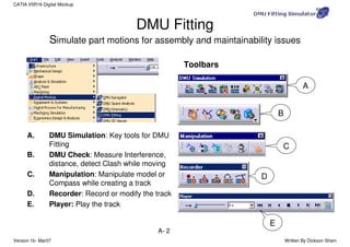
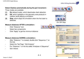
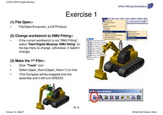
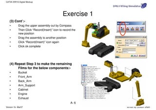
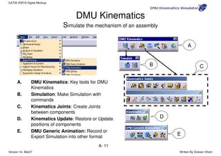
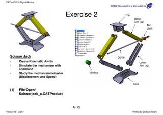
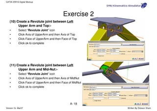
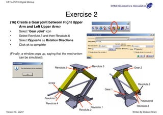
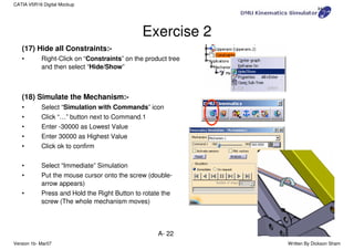
SlideShare a Scribd company logo
Version 1b- Mar07 Written By Dickson Sham
A- 1
CATIA V5R16 Digital Mockup
CATIA V5
Digital Mockup (DMU)
Version 5 Release 16
DMU Fitting
DMU Kinematics
Version 1b- Mar07 Written By Dickson Sham
A- 2
CATIA V5R16 Digital Mockup
DMU Fitting
Simulate part motions for assembly and maintainability issues
A. DMU Simulation: Key tools for DMU
Fitting
B. DMU Check: Measure Interference,
distance, detect Clash while moving
C. Manipulation: Manipulate model or
Compass while creating a track
D. Recorder: Record or modify the track
E. Player: Play the track
A
C
D
B
E
Toolbars
Version 1b- Mar07 Written By Dickson Sham
A- 3
CATIA V5R16 Digital Mockup
Open an Assembly Document
Create a Track
Move a Component
Record the Track
Repeat creating tracks for other components
Create a Sequence of Tracks
Create a Simulation
Analyze the results and modify the design if
necessary
General Process
Using DMU Manipulation Toolbar to
change the position of the Compass:-
1) “Detach” the Compass from
the selected Part (it will be
gray)
2) “Snap” the Compass onto a
new position
3) “Attach” the Compass
again (it will be Green)
Version 1b- Mar07 Written By Dickson Sham
A- 4
CATIA V5R16 Digital Mockup
Detect Clashes automatically during the part movement:-
Three modes are available:
(1) On (default mode), which deactivates clash detection
(2) Off, which highlights in the geometry area products in
collision while playing a simulation
(3) Stop, which stops the simulation when the first clash is
detected.
Measure distances AFTER a simulation:-
- Click “Distance” icon
- Select two components
- Click “Apply” to get the minimum distance
Measure distances DURING a simulation:-
- After “Distance.1” is created, double-click “Sequence.1” on
the tree
- Select the Tab Page “ Edit Analysis”
- Put “Distance.1” on the list called “Analyses in Sequence”
- Set it Active
On/ Off/ Stop
Version 1b- Mar07 Written By Dickson Sham
A- 5
CATIA V5R16 Digital Mockup
(1) File Open:-
• File/Open/Excavator_a.CATProduct
(2) Change workbench to DMU Fitting:-
• If the current workbench is not “DMU Fitting”,
select “Start/Digital Mockup/ DMU fitting” on
the top menu to change. (otherwise, it needn’t
change)
(3) Make the 1st Film:-
• Click “Track” icon
• Select Upper_Assm(Upper_Assm.1) on tree
• (The Compass will be snapped onto the
assembly and it will turn GREEN)
Exercise 1
Version 1b- Mar07 Written By Dickson Sham
A- 6
CATIA V5R16 Digital Mockup
(3) Cont’:-
• Drag the upper assembly out by Compass
• Then Click “Record(Insert)” icon to record the
new position
• Drag the assembly to another position
• Click “Record(Insert)” icon again
• Click ok complete
(4) Repeat Step 3 to make the remaining
Films for the below components:-
• Bucket
• Front_Arm
• Back_Arm
• Arm_Support
• Cabinet
• Engine
• Exhaust
Exercise 1
Version 1b- Mar07 Written By Dickson Sham
A- 7
CATIA V5R16 Digital Mockup
(5) Create a Play Sequence of the films:-
• Click “Edit Sequence” icon
• Select Track.1 under the list of “Action in
session”
• Click
• Select Track.2, then
• …Repeat the steps until all Tracks are inserted
(6) Play the Sequence of films:-
• Click “Simulation Player” icon
• Select Sequence.1
• (The Player is activated on top of the screen)
• Click “Parameters” icon
• Enter 5s as Sampling Step (Run the simulation
faster)
• Click
Exercise 1
Version 1b- Mar07 Written By Dickson Sham
A- 8
CATIA V5R16 Digital Mockup
(6) Cont’:-
• Click “Change Loop Mode” icon to run the
simulation continuously
• Click “Stop” icon to stop
• Click “Simulation Player” icon again to exit
(7) Reset the positions:-
• Click “Reset Position” icon
• (all components will be back to their original
positions)
(8) Hide all Track Lines on screen:-
• Right-Click “Tracks” on the tree
• Select “Hide/Show”
Exercise 1
Change Loop
Mode
Stop
Version 1b- Mar07 Written By Dickson Sham
A- 9
CATIA V5R16 Digital Mockup
(9) Refine Environment Settings (optional):-
• To improve the resolution, select
“Tools/options…/General/Display/Performan
ces/3D Accuracy/Fixed” on the top menu and
change it to 0.01(smallest value)
• Change the shading mode to “Shading with
Material”
• Select “View/Render Style/Perspective” on
the menu
• Select “View/ Lighting…” and then select “Two
Lights”
• To Hide Compass, Deselect “View/ Compass”
on the top menu
• To Hide Tree, Deselect “View/ Specifications”
on the top menu
Exercise 1
Version 1b- Mar07 Written By Dickson Sham
A- 10
CATIA V5R16 Digital Mockup
(10) Export Simulation into AVI format
• Click “Tools/Simulation/Generate Video” on
the top menu
• Select Sequence.1 on tree
• Select “VFW Codec” as default
• Click “Setup” button and select “Cinepak
Codec by Radius” as Compressor
• Click “File name…” to define the destination
of the exported file and the file name
• Click ok to complete
(Remark: During the conversion, we can manipulate
the geometry by mouse)
Exercise 1
END of Exercise 1
Version 1b- Mar07 Written By Dickson Sham
A- 11
CATIA V5R16 Digital Mockup
DMU Kinematics
Simulate the mechanism of an assembly
A. DMU Kinematics: Key tools for DMU
Kinematics
B. Simulation: Make Simulation with
commands
C. Kinematics Joints: Create Joints
between components
D. Kinematics Update: Restore or Update
positions of components
E. DMU Generic Animation: Record or
Export Simulation into other format
A
B C
D
E
Version 1b- Mar07 Written By Dickson Sham
A- 12
CATIA V5R16 Digital Mockup
Open an Assembly Document
Delete all Constraints & Create Joints manually
-Or-
Convert Constraints into Mechanism
Browse the Mechanism with Commands
Create a Simulation
Analyze the results and modify the design if
necessary
General Process
Version 1b- Mar07 Written By Dickson Sham
A- 13
CATIA V5R16 Digital Mockup
Scissor Jack
- Create Kinematic Joints
- Simulate the mechanism with
command
- Study the mechanism behavior
(Displacement and Speed)
(1) File/Open/
Scissorjack_a.CATProduct
Exercise 2 Top
Upper
Arm (x2)
Screw
Base
Lower
Arm (x2)
Mid
Joint
Mid Nut
Version 1b- Mar07 Written By Dickson Sham
A- 14
CATIA V5R16 Digital Mockup
(2) Change workbench to DMU kinematics:-
• If the current workbench is not “DMU
kinematics”, select “Start/Digital Mockup/
DMU kinematics” on the top menu to change.
(otherwise, it needn’t change)
(3) Delete all Constraints:-
• Right-Click on “Constraints” on the product
tree and then select “Delete”
• (We are going to create kinematic joints
manually. Once a joint is created between two
parts, the corresponding constraints will be
made automatically between them. To prevent
redundancy, we need to delete all the
constraints, which were made on the
“Assembly Design” workbench, before creating
joints.)
Exercise 2
Version 1b- Mar07 Written By Dickson Sham
A- 15
CATIA V5R16 Digital Mockup
(4) Fix “Base” in place:-
• Select “Fixed Part” icon
• Click “New Mechanism” icon on the pop-up
window
• Click ok to accept the default name
• Select “Base” (by clicking “Base” on tree or
clicking on the geometry directly)
• (A Fix Constraint is created automatically, and at
the same time, a fixed part is defined in
Mechanism.1)
(5) Create a Revolute joint between Right
Lower Arm and Base:-
• Select “Revolute Joint” icon
• Click Axis of LowerArm and then Axis of Base (Put
the mouse cursor onto the cylindrical surface to
get its axis)
• Click Face of LowerArm and then Face of Base
• Click ok to complete
Exercise 2
Version 1b- Mar07 Written By Dickson Sham
A- 16
CATIA V5R16 Digital Mockup
(6) Create a Revolute joint between Left Lower
Arm and Base:-
• Select “Revolute Joint” icon
• Click Axis of LowerArm and then Axis of Base
• Click Face of LowerArm and then Face of Base
• Click ok to complete
(7) Create a Revolute joint between Right
Lower Arm and Right Upper Arm:-
• Select “Revolute Joint” icon
• Click Axis of LowerArm and then Axis of UpperArm
• Click Face of LowerArm and then Face of
UpperArm
• Click ok to complete
Exercise 2
Version 1b- Mar07 Written By Dickson Sham
A- 17
CATIA V5R16 Digital Mockup
(8) Create a Revolute joint between Left Lower
Arm and Left Upper Arm:-
• Select “Revolute Joint” icon
• Click Axis of LowerArm and then Axis of UpperArm
• Click Face of LowerArm and then Face of
UpperArm
• Click ok to complete
(9) Create a Revolute joint between Right
Upper Arm and Top:-
• Select “Revolute Joint” icon
• Click Axis of UpperArm and then Axis of Top
• Click Face of UpperArm and then Face of Top
• Click ok to complete
Exercise 2
Version 1b- Mar07 Written By Dickson Sham
A- 18
CATIA V5R16 Digital Mockup
(10) Create a Revolute joint between Left
Upper Arm and Top:-
• Select “Revolute Joint” icon
• Click Axis of UpperArm and then Axis of Top
• Click Face of UpperArm and then Face of Top
• Click ok to complete
(11) Create a Revolute joint between Left
Upper Arm and Mid-Nut:-
• Select “Revolute Joint” icon
• Click Axis of UpperArm and then Axis of MidNut
• Click Face of UpperArm and then Face of MidNut
• Click ok to complete
Exercise 2
Version 1b- Mar07 Written By Dickson Sham
A- 19
CATIA V5R16 Digital Mockup
(12) Create a Revolute joint between Right
Upper Arm and Mid-Joint:-
• Select “Revolute Joint” icon
• Click Axis of UpperArm and then Axis of Midjoint
• Click Face of UpperArm and then Face of MidJoint
• Click ok to complete
(13) Create a Revolute joint between Mid-Joint
and Screw:-
• Drag the Screw out of the hole by Compass
• Show xy-plane, yz-plane & zx plane of Mid-Joint
• Select “Revolute Joint” icon
• Click Axis of Mid-Joint and then Axis of Screw
• Click zx Plane of Mid-Joint and then Face of Screw
• Enter 10mm as Offset
• Click ok to complete
• Hide xy-plane, yz-plane & zx plane
Exercise 2
Select this
planar face
Version 1b- Mar07 Written By Dickson Sham
A- 20
CATIA V5R16 Digital Mockup
(14) Create a Screw joint between Mid-Nut and
Screw:-
• Drag the Screw out of the hole by Compass again
so that we can see the screw hole
• Select “Screw Joint” icon
• Click Axis of MidNut and then Axis of Screw
• Select “angle driven” option
• Enter 1 as Pitch
• Click ok to complete
(15) Create a Gear joint between Right Lower
Arm and Left Lower Arm:-
• Select “Gear Joint” icon
• Select Revolute.1 and then Revolute.2
• Select Opposite as Rotation Directions
• Click ok to complete
Exercise 2
Version 1b- Mar07 Written By Dickson Sham
A- 21
CATIA V5R16 Digital Mockup
(16) Create a Gear joint between Right Upper
Arm and Left Upper Arm:-
• Select “Gear Joint” icon
• Select Revolute.5 and then Revolute.6
• Select Opposite as Rotation Directions
• Click ok to complete
(Finally, a window pops up, saying that the mechanism
can be simulated)
Exercise 2
Gear.2
Gear.1
screw
Revolute.1
Revolute.4
Revolute.7
Revolute.6 Revolute.5
Revolute.2
Revolute.9
Revolute.3
Revolute.8
Version 1b- Mar07 Written By Dickson Sham
A- 22
CATIA V5R16 Digital Mockup
(17) Hide all Constraints:-
• Right-Click on “Constraints” on the product tree
and then select “Hide/Show”
(18) Simulate the Mechanism:-
• Select “Simulation with Commands” icon
• Click “…” button next to Command.1
• Enter -30000 as Lowest Value
• Enter 30000 as Highest Value
• Click ok to confirm
• Select “Immediate” Simulation
• Put the mouse cursor onto the screw (double-
arrow appears)
• Press and Hold the Right Button to rotate the
screw (The whole mechanism moves)
Exercise 2
Version 1b- Mar07 Written By Dickson Sham
A- 23
CATIA V5R16 Digital Mockup
(19) Get the Smallest Height of Scissor Jack:-
• Select “Activate Sensors” option (another menu
pops-up)
• Select the third button “Stop when Clash”
• Select “On Request” Simulation
• Select 40 as Number of steps
• Adjust Command.1 to -30000 (lowest value)
• Click “Play” icon
• (The mechanism moves until the clash occurs;
When Command.1 is ~21000, it stops)
• Select “Close” on both menus
(20) Reset Command.1 to Zero:-
• Double-Click Command.1 on tree
• Click “Reset to Zero” button
• Click ok to complete
• (Now when Command.1=0 deg, the scissor jack is
the shortest)
Exercise 2
It is now fully contracted
Version 1b- Mar07 Written By Dickson Sham
A- 24
CATIA V5R16 Digital Mockup
(21) Define the relation between Command.1
and Time:-
• Click “Formula” icon
• Click Mechanism.1 on tree
• (Two related parameters are sorted out:
“Mechanism.1KINTime” &
“Mechanism.1CommandsCommand.1Angle”)
• Select
“Mechanism.1CommandsCommand.1Angle”
• Click “Add Formula” button
• Enter (Mechanism.1KINTime /1s)*360*2deg
• Click ok
• Click ok again
• (The formula is now stored under Mechanism.1)
Exercise 2
Version 1b- Mar07 Written By Dickson Sham
A- 25
CATIA V5R16 Digital Mockup
(22) Define a Sensor:-
• Click “Speed and Acceleration” icon
• Select Base as Reference Product
• Select any endpoint of the Top
face as Point Selection
• Select “Main axis”
• (Remark: “Main Axis” is the axis
system of the Product, which is also
the axis system of Base (1st
component))
• Click ok to complete
(23) Run the Simulation with
Formula:-
• Click “Simulation with Laws” icon
Exercise 2
Version 1b- Mar07 Written By Dickson Sham
A- 26
CATIA V5R16 Digital Mockup
(23) Con’t:-
• Select “Activate Sensors”
• Select “Speed-Acceleration.1z_vertex” and
“Speed-Acceleration.1z_LinearSpeed”
• Click “Stop when Clash” button
• Click “…” button
• Enter 200s as Maximum time bound
• Click ok
• Click button
(The mechanism moves, but stops at ~130s when
clash is detected)
Exercise 2
Version 1b- Mar07 Written By Dickson Sham
A- 27
CATIA V5R16 Digital Mockup
(24) Study Results:-
• Click “Graphics…” button
• We get two curves on the graph:
Yellow – Displacement of the Top Face;
Green – Speed of the Top Face
• Smallest Height = 95mm
• Largest Height = 326mm
• Range = (326-95) = 231mm
• Total Time (from Full contraction to Full
Extension) = 133sec (assuming the angular
speed of the screw is 2 rev/sec)
(25) Restore original positions:-
• Click “Reset Positions” button
Exercise 2
Displacement
Speed
END of Exercise 2

More Related Content

Similar to catia-v5-dmu-kinematics.pdf

Nx basics 2014 unfnished
Nx basics 2014 unfnishedNx basics 2014 unfnished
Nx basics 2014 unfnished
Miguele Davila
 
Autodesk 3ds max design 2010 tutorial
Autodesk 3ds max design 2010 tutorialAutodesk 3ds max design 2010 tutorial
Autodesk 3ds max design 2010 tutorial
George Livanos
 
AUTOCAD Report
AUTOCAD ReportAUTOCAD Report
AUTOCAD Report
AMIT RAJ
 
solidworks
solidworkssolidworks
solidworks
Amit Kamboj
 
solidworks
solidworkssolidworks
solidworks
Amit Kamboj
 
Solidworks tips - First edition.pdf
Solidworks tips - First edition.pdfSolidworks tips - First edition.pdf
Solidworks tips - First edition.pdf
ZaheerAhmed905221
 
Introduction to CATIA (KEY) - CAD/CAM
Introduction to CATIA (KEY) - CAD/CAMIntroduction to CATIA (KEY) - CAD/CAM
Introduction to CATIA (KEY) - CAD/CAM
Sisubalan Selvan
 
Motor3 d v13
Motor3 d v13Motor3 d v13
Motor3 d v13
ramdanelateb
 
Portfolio-PDF
Portfolio-PDFPortfolio-PDF
Portfolio-PDF
David Trick
 
Runner
RunnerRunner
Runner
AlexDaStar
 
Xmastcamcribboard
XmastcamcribboardXmastcamcribboard
Xmastcamcribboard
doglupo
 
Inventor project-dynamic-simulation-guide-en
Inventor project-dynamic-simulation-guide-enInventor project-dynamic-simulation-guide-en
Inventor project-dynamic-simulation-guide-en
julio valverde cruz
 
InnerSoft CAD Manual
InnerSoft CAD ManualInnerSoft CAD Manual
InnerSoft CAD Manual
InnerSoft
 
PRO ENGINEER BASIC
PRO ENGINEER BASICPRO ENGINEER BASIC
PRO ENGINEER BASIC
Parveen Kumar
 
13858158.ppt
13858158.ppt13858158.ppt
13858158.ppt
AffanWaheed6
 
Solid_Modeling_Project_Reverse engineering of a computer mouse and documentat...
Solid_Modeling_Project_Reverse engineering of a computer mouse and documentat...Solid_Modeling_Project_Reverse engineering of a computer mouse and documentat...
Solid_Modeling_Project_Reverse engineering of a computer mouse and documentat...
Mehmet Bariskan
 
Visi progress
Visi progressVisi progress
Visi progress
Frankey Sun
 
3 d autocad
3 d autocad3 d autocad
3 d autocad
Cleverson Leite
 
3 d autocad
3 d autocad3 d autocad
3 d autocad
danny perez
 
AutoCAD - 3D Notes
AutoCAD - 3D NotesAutoCAD - 3D Notes
AutoCAD - 3D Notes
Vj NiroSh
 

Similar to catia-v5-dmu-kinematics.pdf (20)

Nx basics 2014 unfnished
Nx basics 2014 unfnishedNx basics 2014 unfnished
Nx basics 2014 unfnished
 
Autodesk 3ds max design 2010 tutorial
Autodesk 3ds max design 2010 tutorialAutodesk 3ds max design 2010 tutorial
Autodesk 3ds max design 2010 tutorial
 
AUTOCAD Report
AUTOCAD ReportAUTOCAD Report
AUTOCAD Report
 
solidworks
solidworkssolidworks
solidworks
 
solidworks
solidworkssolidworks
solidworks
 
Solidworks tips - First edition.pdf
Solidworks tips - First edition.pdfSolidworks tips - First edition.pdf
Solidworks tips - First edition.pdf
 
Introduction to CATIA (KEY) - CAD/CAM
Introduction to CATIA (KEY) - CAD/CAMIntroduction to CATIA (KEY) - CAD/CAM
Introduction to CATIA (KEY) - CAD/CAM
 
Motor3 d v13
Motor3 d v13Motor3 d v13
Motor3 d v13
 
Portfolio-PDF
Portfolio-PDFPortfolio-PDF
Portfolio-PDF
 
Runner
RunnerRunner
Runner
 
Xmastcamcribboard
XmastcamcribboardXmastcamcribboard
Xmastcamcribboard
 
Inventor project-dynamic-simulation-guide-en
Inventor project-dynamic-simulation-guide-enInventor project-dynamic-simulation-guide-en
Inventor project-dynamic-simulation-guide-en
 
InnerSoft CAD Manual
InnerSoft CAD ManualInnerSoft CAD Manual
InnerSoft CAD Manual
 
PRO ENGINEER BASIC
PRO ENGINEER BASICPRO ENGINEER BASIC
PRO ENGINEER BASIC
 
13858158.ppt
13858158.ppt13858158.ppt
13858158.ppt
 
Solid_Modeling_Project_Reverse engineering of a computer mouse and documentat...
Solid_Modeling_Project_Reverse engineering of a computer mouse and documentat...Solid_Modeling_Project_Reverse engineering of a computer mouse and documentat...
Solid_Modeling_Project_Reverse engineering of a computer mouse and documentat...
 
Visi progress
Visi progressVisi progress
Visi progress
 
3 d autocad
3 d autocad3 d autocad
3 d autocad
 
3 d autocad
3 d autocad3 d autocad
3 d autocad
 
AutoCAD - 3D Notes
AutoCAD - 3D NotesAutoCAD - 3D Notes
AutoCAD - 3D Notes
 

Recently uploaded

一比一原版布兰登大学毕业证(BU毕业证书)如何办理
一比一原版布兰登大学毕业证(BU毕业证书)如何办理一比一原版布兰登大学毕业证(BU毕业证书)如何办理
一比一原版布兰登大学毕业证(BU毕业证书)如何办理
wkip62b
 
一比一原版(爱大毕业证)美国爱荷华大学毕业证如何办理
一比一原版(爱大毕业证)美国爱荷华大学毕业证如何办理一比一原版(爱大毕业证)美国爱荷华大学毕业证如何办理
一比一原版(爱大毕业证)美国爱荷华大学毕业证如何办理
ynrtjotp
 
一比一原版(Deakin毕业证书)澳洲迪肯大学毕业证文凭如何办理
一比一原版(Deakin毕业证书)澳洲迪肯大学毕业证文凭如何办理一比一原版(Deakin毕业证书)澳洲迪肯大学毕业证文凭如何办理
一比一原版(Deakin毕业证书)澳洲迪肯大学毕业证文凭如何办理
k4krdgxx
 
International Upcycling Research Network advisory board meeting 4
International Upcycling Research Network advisory board meeting 4International Upcycling Research Network advisory board meeting 4
International Upcycling Research Network advisory board meeting 4
Kyungeun Sung
 
一比一原版(ututaustin毕业证书)美国德克萨斯大学奥斯汀分校毕业证如何办理
一比一原版(ututaustin毕业证书)美国德克萨斯大学奥斯汀分校毕业证如何办理一比一原版(ututaustin毕业证书)美国德克萨斯大学奥斯汀分校毕业证如何办理
一比一原版(ututaustin毕业证书)美国德克萨斯大学奥斯汀分校毕业证如何办理
yqyquge
 
一比一原版(UoB毕业证)英国伯明翰大学毕业证如何办理
一比一原版(UoB毕业证)英国伯明翰大学毕业证如何办理一比一原版(UoB毕业证)英国伯明翰大学毕业证如何办理
一比一原版(UoB毕业证)英国伯明翰大学毕业证如何办理
zv943dhb
 
一比一原版(NU毕业证书)诺森比亚大学毕业证如何办理
一比一原版(NU毕业证书)诺森比亚大学毕业证如何办理一比一原版(NU毕业证书)诺森比亚大学毕业证如何办理
一比一原版(NU毕业证书)诺森比亚大学毕业证如何办理
21uul8se
 
Getting Data Ready for Culture Hack by Neontribe
Getting Data Ready for Culture Hack by NeontribeGetting Data Ready for Culture Hack by Neontribe
Getting Data Ready for Culture Hack by Neontribe
Harry Harrold
 
一比一原版(KPU毕业证)加拿大昆特兰理工大学毕业证如何办理
一比一原版(KPU毕业证)加拿大昆特兰理工大学毕业证如何办理一比一原版(KPU毕业证)加拿大昆特兰理工大学毕业证如何办理
一比一原版(KPU毕业证)加拿大昆特兰理工大学毕业证如何办理
kmzsy4kn
 
一比一原版(Rice毕业证)美国莱斯大学毕业证如何办理
一比一原版(Rice毕业证)美国莱斯大学毕业证如何办理一比一原版(Rice毕业证)美国莱斯大学毕业证如何办理
一比一原版(Rice毕业证)美国莱斯大学毕业证如何办理
oabn3692
 
一比一原版马里兰大学毕业证(UMD毕业证书)如何办理
一比一原版马里兰大学毕业证(UMD毕业证书)如何办理一比一原版马里兰大学毕业证(UMD毕业证书)如何办理
一比一原版马里兰大学毕业证(UMD毕业证书)如何办理
9lq7ultg
 
一比一原版(UCB毕业证)英国伯明翰大学学院毕业证如何办理
一比一原版(UCB毕业证)英国伯明翰大学学院毕业证如何办理一比一原版(UCB毕业证)英国伯明翰大学学院毕业证如何办理
一比一原版(UCB毕业证)英国伯明翰大学学院毕业证如何办理
zv943dhb
 
NHL Stenden University of Applied Sciences Diploma Degree Transcript
NHL Stenden University of Applied Sciences Diploma Degree TranscriptNHL Stenden University of Applied Sciences Diploma Degree Transcript
NHL Stenden University of Applied Sciences Diploma Degree Transcript
lhtvqoag
 
一比一原版(LSBU毕业证书)伦敦南岸大学毕业证如何办理
一比一原版(LSBU毕业证书)伦敦南岸大学毕业证如何办理一比一原版(LSBU毕业证书)伦敦南岸大学毕业证如何办理
一比一原版(LSBU毕业证书)伦敦南岸大学毕业证如何办理
k7nm6tk
 
一比一原版美国旧金山大学毕业证(USF学位证)如何办理
一比一原版美国旧金山大学毕业证(USF学位证)如何办理一比一原版美国旧金山大学毕业证(USF学位证)如何办理
一比一原版美国旧金山大学毕业证(USF学位证)如何办理
xnhwr8v
 
Practical eLearning Makeovers for Everyone
Practical eLearning Makeovers for EveryonePractical eLearning Makeovers for Everyone
Practical eLearning Makeovers for Everyone
Bianca Woods
 
一比一原版美国哥伦比亚大学毕业证Columbia成绩单一模一样
一比一原版美国哥伦比亚大学毕业证Columbia成绩单一模一样一比一原版美国哥伦比亚大学毕业证Columbia成绩单一模一样
一比一原版美国哥伦比亚大学毕业证Columbia成绩单一模一样
881evgn0
 
一比一原版(UWE毕业证书)西英格兰大学毕业证如何办理
一比一原版(UWE毕业证书)西英格兰大学毕业证如何办理一比一原版(UWE毕业证书)西英格兰大学毕业证如何办理
一比一原版(UWE毕业证书)西英格兰大学毕业证如何办理
etls06p8
 
Best Digital Marketing Strategy Build Your Online Presence 2024.pptx
Best Digital Marketing Strategy Build  Your Online Presence 2024.pptxBest Digital Marketing Strategy Build  Your Online Presence 2024.pptx
Best Digital Marketing Strategy Build Your Online Presence 2024.pptx
pavankumarpayexelsol
 
一比一原版(Brunel毕业证)英国布鲁内尔大学毕业证如何办理
一比一原版(Brunel毕业证)英国布鲁内尔大学毕业证如何办理一比一原版(Brunel毕业证)英国布鲁内尔大学毕业证如何办理
一比一原版(Brunel毕业证)英国布鲁内尔大学毕业证如何办理
ka3y2ukz
 

Recently uploaded (20)

一比一原版布兰登大学毕业证(BU毕业证书)如何办理
一比一原版布兰登大学毕业证(BU毕业证书)如何办理一比一原版布兰登大学毕业证(BU毕业证书)如何办理
一比一原版布兰登大学毕业证(BU毕业证书)如何办理
 
一比一原版(爱大毕业证)美国爱荷华大学毕业证如何办理
一比一原版(爱大毕业证)美国爱荷华大学毕业证如何办理一比一原版(爱大毕业证)美国爱荷华大学毕业证如何办理
一比一原版(爱大毕业证)美国爱荷华大学毕业证如何办理
 
一比一原版(Deakin毕业证书)澳洲迪肯大学毕业证文凭如何办理
一比一原版(Deakin毕业证书)澳洲迪肯大学毕业证文凭如何办理一比一原版(Deakin毕业证书)澳洲迪肯大学毕业证文凭如何办理
一比一原版(Deakin毕业证书)澳洲迪肯大学毕业证文凭如何办理
 
International Upcycling Research Network advisory board meeting 4
International Upcycling Research Network advisory board meeting 4International Upcycling Research Network advisory board meeting 4
International Upcycling Research Network advisory board meeting 4
 
一比一原版(ututaustin毕业证书)美国德克萨斯大学奥斯汀分校毕业证如何办理
一比一原版(ututaustin毕业证书)美国德克萨斯大学奥斯汀分校毕业证如何办理一比一原版(ututaustin毕业证书)美国德克萨斯大学奥斯汀分校毕业证如何办理
一比一原版(ututaustin毕业证书)美国德克萨斯大学奥斯汀分校毕业证如何办理
 
一比一原版(UoB毕业证)英国伯明翰大学毕业证如何办理
一比一原版(UoB毕业证)英国伯明翰大学毕业证如何办理一比一原版(UoB毕业证)英国伯明翰大学毕业证如何办理
一比一原版(UoB毕业证)英国伯明翰大学毕业证如何办理
 
一比一原版(NU毕业证书)诺森比亚大学毕业证如何办理
一比一原版(NU毕业证书)诺森比亚大学毕业证如何办理一比一原版(NU毕业证书)诺森比亚大学毕业证如何办理
一比一原版(NU毕业证书)诺森比亚大学毕业证如何办理
 
Getting Data Ready for Culture Hack by Neontribe
Getting Data Ready for Culture Hack by NeontribeGetting Data Ready for Culture Hack by Neontribe
Getting Data Ready for Culture Hack by Neontribe
 
一比一原版(KPU毕业证)加拿大昆特兰理工大学毕业证如何办理
一比一原版(KPU毕业证)加拿大昆特兰理工大学毕业证如何办理一比一原版(KPU毕业证)加拿大昆特兰理工大学毕业证如何办理
一比一原版(KPU毕业证)加拿大昆特兰理工大学毕业证如何办理
 
一比一原版(Rice毕业证)美国莱斯大学毕业证如何办理
一比一原版(Rice毕业证)美国莱斯大学毕业证如何办理一比一原版(Rice毕业证)美国莱斯大学毕业证如何办理
一比一原版(Rice毕业证)美国莱斯大学毕业证如何办理
 
一比一原版马里兰大学毕业证(UMD毕业证书)如何办理
一比一原版马里兰大学毕业证(UMD毕业证书)如何办理一比一原版马里兰大学毕业证(UMD毕业证书)如何办理
一比一原版马里兰大学毕业证(UMD毕业证书)如何办理
 
一比一原版(UCB毕业证)英国伯明翰大学学院毕业证如何办理
一比一原版(UCB毕业证)英国伯明翰大学学院毕业证如何办理一比一原版(UCB毕业证)英国伯明翰大学学院毕业证如何办理
一比一原版(UCB毕业证)英国伯明翰大学学院毕业证如何办理
 
NHL Stenden University of Applied Sciences Diploma Degree Transcript
NHL Stenden University of Applied Sciences Diploma Degree TranscriptNHL Stenden University of Applied Sciences Diploma Degree Transcript
NHL Stenden University of Applied Sciences Diploma Degree Transcript
 
一比一原版(LSBU毕业证书)伦敦南岸大学毕业证如何办理
一比一原版(LSBU毕业证书)伦敦南岸大学毕业证如何办理一比一原版(LSBU毕业证书)伦敦南岸大学毕业证如何办理
一比一原版(LSBU毕业证书)伦敦南岸大学毕业证如何办理
 
一比一原版美国旧金山大学毕业证(USF学位证)如何办理
一比一原版美国旧金山大学毕业证(USF学位证)如何办理一比一原版美国旧金山大学毕业证(USF学位证)如何办理
一比一原版美国旧金山大学毕业证(USF学位证)如何办理
 
Practical eLearning Makeovers for Everyone
Practical eLearning Makeovers for EveryonePractical eLearning Makeovers for Everyone
Practical eLearning Makeovers for Everyone
 
一比一原版美国哥伦比亚大学毕业证Columbia成绩单一模一样
一比一原版美国哥伦比亚大学毕业证Columbia成绩单一模一样一比一原版美国哥伦比亚大学毕业证Columbia成绩单一模一样
一比一原版美国哥伦比亚大学毕业证Columbia成绩单一模一样
 
一比一原版(UWE毕业证书)西英格兰大学毕业证如何办理
一比一原版(UWE毕业证书)西英格兰大学毕业证如何办理一比一原版(UWE毕业证书)西英格兰大学毕业证如何办理
一比一原版(UWE毕业证书)西英格兰大学毕业证如何办理
 
Best Digital Marketing Strategy Build Your Online Presence 2024.pptx
Best Digital Marketing Strategy Build  Your Online Presence 2024.pptxBest Digital Marketing Strategy Build  Your Online Presence 2024.pptx
Best Digital Marketing Strategy Build Your Online Presence 2024.pptx
 
一比一原版(Brunel毕业证)英国布鲁内尔大学毕业证如何办理
一比一原版(Brunel毕业证)英国布鲁内尔大学毕业证如何办理一比一原版(Brunel毕业证)英国布鲁内尔大学毕业证如何办理
一比一原版(Brunel毕业证)英国布鲁内尔大学毕业证如何办理
 

catia-v5-dmu-kinematics.pdf

  • 1. Version 1b- Mar07 Written By Dickson Sham A- 1 CATIA V5R16 Digital Mockup CATIA V5 Digital Mockup (DMU) Version 5 Release 16 DMU Fitting DMU Kinematics
  • 2. Version 1b- Mar07 Written By Dickson Sham A- 2 CATIA V5R16 Digital Mockup DMU Fitting Simulate part motions for assembly and maintainability issues A. DMU Simulation: Key tools for DMU Fitting B. DMU Check: Measure Interference, distance, detect Clash while moving C. Manipulation: Manipulate model or Compass while creating a track D. Recorder: Record or modify the track E. Player: Play the track A C D B E Toolbars
  • 3. Version 1b- Mar07 Written By Dickson Sham A- 3 CATIA V5R16 Digital Mockup Open an Assembly Document Create a Track Move a Component Record the Track Repeat creating tracks for other components Create a Sequence of Tracks Create a Simulation Analyze the results and modify the design if necessary General Process Using DMU Manipulation Toolbar to change the position of the Compass:- 1) “Detach” the Compass from the selected Part (it will be gray) 2) “Snap” the Compass onto a new position 3) “Attach” the Compass again (it will be Green)
  • 4. Version 1b- Mar07 Written By Dickson Sham A- 4 CATIA V5R16 Digital Mockup Detect Clashes automatically during the part movement:- Three modes are available: (1) On (default mode), which deactivates clash detection (2) Off, which highlights in the geometry area products in collision while playing a simulation (3) Stop, which stops the simulation when the first clash is detected. Measure distances AFTER a simulation:- - Click “Distance” icon - Select two components - Click “Apply” to get the minimum distance Measure distances DURING a simulation:- - After “Distance.1” is created, double-click “Sequence.1” on the tree - Select the Tab Page “ Edit Analysis” - Put “Distance.1” on the list called “Analyses in Sequence” - Set it Active On/ Off/ Stop
  • 5. Version 1b- Mar07 Written By Dickson Sham A- 5 CATIA V5R16 Digital Mockup (1) File Open:- • File/Open/Excavator_a.CATProduct (2) Change workbench to DMU Fitting:- • If the current workbench is not “DMU Fitting”, select “Start/Digital Mockup/ DMU fitting” on the top menu to change. (otherwise, it needn’t change) (3) Make the 1st Film:- • Click “Track” icon • Select Upper_Assm(Upper_Assm.1) on tree • (The Compass will be snapped onto the assembly and it will turn GREEN) Exercise 1
  • 6. Version 1b- Mar07 Written By Dickson Sham A- 6 CATIA V5R16 Digital Mockup (3) Cont’:- • Drag the upper assembly out by Compass • Then Click “Record(Insert)” icon to record the new position • Drag the assembly to another position • Click “Record(Insert)” icon again • Click ok complete (4) Repeat Step 3 to make the remaining Films for the below components:- • Bucket • Front_Arm • Back_Arm • Arm_Support • Cabinet • Engine • Exhaust Exercise 1
  • 7. Version 1b- Mar07 Written By Dickson Sham A- 7 CATIA V5R16 Digital Mockup (5) Create a Play Sequence of the films:- • Click “Edit Sequence” icon • Select Track.1 under the list of “Action in session” • Click • Select Track.2, then • …Repeat the steps until all Tracks are inserted (6) Play the Sequence of films:- • Click “Simulation Player” icon • Select Sequence.1 • (The Player is activated on top of the screen) • Click “Parameters” icon • Enter 5s as Sampling Step (Run the simulation faster) • Click Exercise 1
  • 8. Version 1b- Mar07 Written By Dickson Sham A- 8 CATIA V5R16 Digital Mockup (6) Cont’:- • Click “Change Loop Mode” icon to run the simulation continuously • Click “Stop” icon to stop • Click “Simulation Player” icon again to exit (7) Reset the positions:- • Click “Reset Position” icon • (all components will be back to their original positions) (8) Hide all Track Lines on screen:- • Right-Click “Tracks” on the tree • Select “Hide/Show” Exercise 1 Change Loop Mode Stop
  • 9. Version 1b- Mar07 Written By Dickson Sham A- 9 CATIA V5R16 Digital Mockup (9) Refine Environment Settings (optional):- • To improve the resolution, select “Tools/options…/General/Display/Performan ces/3D Accuracy/Fixed” on the top menu and change it to 0.01(smallest value) • Change the shading mode to “Shading with Material” • Select “View/Render Style/Perspective” on the menu • Select “View/ Lighting…” and then select “Two Lights” • To Hide Compass, Deselect “View/ Compass” on the top menu • To Hide Tree, Deselect “View/ Specifications” on the top menu Exercise 1
  • 10. Version 1b- Mar07 Written By Dickson Sham A- 10 CATIA V5R16 Digital Mockup (10) Export Simulation into AVI format • Click “Tools/Simulation/Generate Video” on the top menu • Select Sequence.1 on tree • Select “VFW Codec” as default • Click “Setup” button and select “Cinepak Codec by Radius” as Compressor • Click “File name…” to define the destination of the exported file and the file name • Click ok to complete (Remark: During the conversion, we can manipulate the geometry by mouse) Exercise 1 END of Exercise 1
  • 11. Version 1b- Mar07 Written By Dickson Sham A- 11 CATIA V5R16 Digital Mockup DMU Kinematics Simulate the mechanism of an assembly A. DMU Kinematics: Key tools for DMU Kinematics B. Simulation: Make Simulation with commands C. Kinematics Joints: Create Joints between components D. Kinematics Update: Restore or Update positions of components E. DMU Generic Animation: Record or Export Simulation into other format A B C D E
  • 12. Version 1b- Mar07 Written By Dickson Sham A- 12 CATIA V5R16 Digital Mockup Open an Assembly Document Delete all Constraints & Create Joints manually -Or- Convert Constraints into Mechanism Browse the Mechanism with Commands Create a Simulation Analyze the results and modify the design if necessary General Process
  • 13. Version 1b- Mar07 Written By Dickson Sham A- 13 CATIA V5R16 Digital Mockup Scissor Jack - Create Kinematic Joints - Simulate the mechanism with command - Study the mechanism behavior (Displacement and Speed) (1) File/Open/ Scissorjack_a.CATProduct Exercise 2 Top Upper Arm (x2) Screw Base Lower Arm (x2) Mid Joint Mid Nut
  • 14. Version 1b- Mar07 Written By Dickson Sham A- 14 CATIA V5R16 Digital Mockup (2) Change workbench to DMU kinematics:- • If the current workbench is not “DMU kinematics”, select “Start/Digital Mockup/ DMU kinematics” on the top menu to change. (otherwise, it needn’t change) (3) Delete all Constraints:- • Right-Click on “Constraints” on the product tree and then select “Delete” • (We are going to create kinematic joints manually. Once a joint is created between two parts, the corresponding constraints will be made automatically between them. To prevent redundancy, we need to delete all the constraints, which were made on the “Assembly Design” workbench, before creating joints.) Exercise 2
  • 15. Version 1b- Mar07 Written By Dickson Sham A- 15 CATIA V5R16 Digital Mockup (4) Fix “Base” in place:- • Select “Fixed Part” icon • Click “New Mechanism” icon on the pop-up window • Click ok to accept the default name • Select “Base” (by clicking “Base” on tree or clicking on the geometry directly) • (A Fix Constraint is created automatically, and at the same time, a fixed part is defined in Mechanism.1) (5) Create a Revolute joint between Right Lower Arm and Base:- • Select “Revolute Joint” icon • Click Axis of LowerArm and then Axis of Base (Put the mouse cursor onto the cylindrical surface to get its axis) • Click Face of LowerArm and then Face of Base • Click ok to complete Exercise 2
  • 16. Version 1b- Mar07 Written By Dickson Sham A- 16 CATIA V5R16 Digital Mockup (6) Create a Revolute joint between Left Lower Arm and Base:- • Select “Revolute Joint” icon • Click Axis of LowerArm and then Axis of Base • Click Face of LowerArm and then Face of Base • Click ok to complete (7) Create a Revolute joint between Right Lower Arm and Right Upper Arm:- • Select “Revolute Joint” icon • Click Axis of LowerArm and then Axis of UpperArm • Click Face of LowerArm and then Face of UpperArm • Click ok to complete Exercise 2
  • 17. Version 1b- Mar07 Written By Dickson Sham A- 17 CATIA V5R16 Digital Mockup (8) Create a Revolute joint between Left Lower Arm and Left Upper Arm:- • Select “Revolute Joint” icon • Click Axis of LowerArm and then Axis of UpperArm • Click Face of LowerArm and then Face of UpperArm • Click ok to complete (9) Create a Revolute joint between Right Upper Arm and Top:- • Select “Revolute Joint” icon • Click Axis of UpperArm and then Axis of Top • Click Face of UpperArm and then Face of Top • Click ok to complete Exercise 2
  • 18. Version 1b- Mar07 Written By Dickson Sham A- 18 CATIA V5R16 Digital Mockup (10) Create a Revolute joint between Left Upper Arm and Top:- • Select “Revolute Joint” icon • Click Axis of UpperArm and then Axis of Top • Click Face of UpperArm and then Face of Top • Click ok to complete (11) Create a Revolute joint between Left Upper Arm and Mid-Nut:- • Select “Revolute Joint” icon • Click Axis of UpperArm and then Axis of MidNut • Click Face of UpperArm and then Face of MidNut • Click ok to complete Exercise 2
  • 19. Version 1b- Mar07 Written By Dickson Sham A- 19 CATIA V5R16 Digital Mockup (12) Create a Revolute joint between Right Upper Arm and Mid-Joint:- • Select “Revolute Joint” icon • Click Axis of UpperArm and then Axis of Midjoint • Click Face of UpperArm and then Face of MidJoint • Click ok to complete (13) Create a Revolute joint between Mid-Joint and Screw:- • Drag the Screw out of the hole by Compass • Show xy-plane, yz-plane & zx plane of Mid-Joint • Select “Revolute Joint” icon • Click Axis of Mid-Joint and then Axis of Screw • Click zx Plane of Mid-Joint and then Face of Screw • Enter 10mm as Offset • Click ok to complete • Hide xy-plane, yz-plane & zx plane Exercise 2 Select this planar face
  • 20. Version 1b- Mar07 Written By Dickson Sham A- 20 CATIA V5R16 Digital Mockup (14) Create a Screw joint between Mid-Nut and Screw:- • Drag the Screw out of the hole by Compass again so that we can see the screw hole • Select “Screw Joint” icon • Click Axis of MidNut and then Axis of Screw • Select “angle driven” option • Enter 1 as Pitch • Click ok to complete (15) Create a Gear joint between Right Lower Arm and Left Lower Arm:- • Select “Gear Joint” icon • Select Revolute.1 and then Revolute.2 • Select Opposite as Rotation Directions • Click ok to complete Exercise 2
  • 21. Version 1b- Mar07 Written By Dickson Sham A- 21 CATIA V5R16 Digital Mockup (16) Create a Gear joint between Right Upper Arm and Left Upper Arm:- • Select “Gear Joint” icon • Select Revolute.5 and then Revolute.6 • Select Opposite as Rotation Directions • Click ok to complete (Finally, a window pops up, saying that the mechanism can be simulated) Exercise 2 Gear.2 Gear.1 screw Revolute.1 Revolute.4 Revolute.7 Revolute.6 Revolute.5 Revolute.2 Revolute.9 Revolute.3 Revolute.8
  • 22. Version 1b- Mar07 Written By Dickson Sham A- 22 CATIA V5R16 Digital Mockup (17) Hide all Constraints:- • Right-Click on “Constraints” on the product tree and then select “Hide/Show” (18) Simulate the Mechanism:- • Select “Simulation with Commands” icon • Click “…” button next to Command.1 • Enter -30000 as Lowest Value • Enter 30000 as Highest Value • Click ok to confirm • Select “Immediate” Simulation • Put the mouse cursor onto the screw (double- arrow appears) • Press and Hold the Right Button to rotate the screw (The whole mechanism moves) Exercise 2
  • 23. Version 1b- Mar07 Written By Dickson Sham A- 23 CATIA V5R16 Digital Mockup (19) Get the Smallest Height of Scissor Jack:- • Select “Activate Sensors” option (another menu pops-up) • Select the third button “Stop when Clash” • Select “On Request” Simulation • Select 40 as Number of steps • Adjust Command.1 to -30000 (lowest value) • Click “Play” icon • (The mechanism moves until the clash occurs; When Command.1 is ~21000, it stops) • Select “Close” on both menus (20) Reset Command.1 to Zero:- • Double-Click Command.1 on tree • Click “Reset to Zero” button • Click ok to complete • (Now when Command.1=0 deg, the scissor jack is the shortest) Exercise 2 It is now fully contracted
  • 24. Version 1b- Mar07 Written By Dickson Sham A- 24 CATIA V5R16 Digital Mockup (21) Define the relation between Command.1 and Time:- • Click “Formula” icon • Click Mechanism.1 on tree • (Two related parameters are sorted out: “Mechanism.1KINTime” & “Mechanism.1CommandsCommand.1Angle”) • Select “Mechanism.1CommandsCommand.1Angle” • Click “Add Formula” button • Enter (Mechanism.1KINTime /1s)*360*2deg • Click ok • Click ok again • (The formula is now stored under Mechanism.1) Exercise 2
  • 25. Version 1b- Mar07 Written By Dickson Sham A- 25 CATIA V5R16 Digital Mockup (22) Define a Sensor:- • Click “Speed and Acceleration” icon • Select Base as Reference Product • Select any endpoint of the Top face as Point Selection • Select “Main axis” • (Remark: “Main Axis” is the axis system of the Product, which is also the axis system of Base (1st component)) • Click ok to complete (23) Run the Simulation with Formula:- • Click “Simulation with Laws” icon Exercise 2
  • 26. Version 1b- Mar07 Written By Dickson Sham A- 26 CATIA V5R16 Digital Mockup (23) Con’t:- • Select “Activate Sensors” • Select “Speed-Acceleration.1z_vertex” and “Speed-Acceleration.1z_LinearSpeed” • Click “Stop when Clash” button • Click “…” button • Enter 200s as Maximum time bound • Click ok • Click button (The mechanism moves, but stops at ~130s when clash is detected) Exercise 2
  • 27. Version 1b- Mar07 Written By Dickson Sham A- 27 CATIA V5R16 Digital Mockup (24) Study Results:- • Click “Graphics…” button • We get two curves on the graph: Yellow – Displacement of the Top Face; Green – Speed of the Top Face • Smallest Height = 95mm • Largest Height = 326mm • Range = (326-95) = 231mm • Total Time (from Full contraction to Full Extension) = 133sec (assuming the angular speed of the screw is 2 rev/sec) (25) Restore original positions:- • Click “Reset Positions” button Exercise 2 Displacement Speed END of Exercise 2