
Recommended
More Related Content
Similar to Caterpillar Cat D7E LGP TRACK-TYPE TRACTOR (Prefix TJA) Service Repair Manual (TJA00001 and up).pdf
Similar to Caterpillar Cat D7E LGP TRACK-TYPE TRACTOR (Prefix TJA) Service Repair Manual (TJA00001 and up).pdf (17)
More from f8usueijdmm
More from f8usueijdmm (16)
Recently uploaded
Recently uploaded (20)
Caterpillar Cat D7E LGP TRACK-TYPE TRACTOR (Prefix TJA) Service Repair Manual (TJA00001 and up).pdf
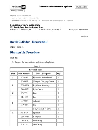
- 1. Shutdown SIS Previous Screen Product: TRACK-TYPE TRACTOR Model: D7E LGP TRACK-TYPE TRACTOR TJA Configuration: D7E TRACK-TYPE TRACTOR LGP TJA00001-UP (MACHINE) POWERED BY C9.3 Engine Disassembly and Assembly D7E Track-Type Tractor Power Train Media Number -KENR5606-03 Publication Date -01/12/2012 Date Updated -05/12/2012 i06007078 Recoil Cylinder - Disassemble SMCS - 4151-015 Disassembly Procedure Start By: A. Remove the track adjuster and the recoil cylinder. Table 1 Required Tools Tool Part Number Part Description Qty A 152-4252 Hydraulic Repair Bench 1 B 175-5507 Nitrogen Charging Group 1 338-0500 Regulator Assembly 1 346-3622 Relief Valve 1 C 8T-0372 Bolt 2 D 1H-3109 Leg 1 5F-9887 Adapter 1 5P-4807 Cap 1 - 1 1/2" Socket 1" Drive 1 E 9U-5919 Spanner 1 209-6756 Clamp As 1 4J-2620 Wear Ring 2 9X-3579 Wear Ring 2 1/10 D7E TRACK-TYPE TRACTOR LGP TJA00001-UP (MACHINE) POWERED BY C... 2021/8/27 https://127.0.0.1/sisweb/sisweb/techdoc/techdoc_print_page.jsp?returnurl=/sis...
- 2. 8T-7850 Wear Ring 2 F FT-3233 Spanner Wrench As. 1 5P-3521 Pin 3 5P-3522 Pin 3 High pressure cylinder. Parts can separate with explosive force if proper care is not used during disassembly. This can cause injury or death. Do not disassemble any part of this cylinder until you have read and understand the instructions given in the service manual. Observe the instructions given in the service manual. Illustration 1 g03483240 1. Secure cylinder (1) to the hydraulic repair bench. 2. Remove bolts (2) and guard (3) . 2/10 D7E TRACK-TYPE TRACTOR LGP TJA00001-UP (MACHINE) POWERED BY C... 2021/8/27 https://127.0.0.1/sisweb/sisweb/techdoc/techdoc_print_page.jsp?returnurl=/sis...
- 3. Illustration 2 g03483316 3. Attach Tooling (A) to valve (4) . Slowly vent the nitrogen from the cylinder, until all pressure is released. Refer to Special Instruction, REHS5464, "Accumulator Discharging and Charging Procedures" for further information. Illustration 3 g03483261 3/10 D7E TRACK-TYPE TRACTOR LGP TJA00001-UP (MACHINE) POWERED BY C... 2021/8/27 https://127.0.0.1/sisweb/sisweb/techdoc/techdoc_print_page.jsp?returnurl=/sis...
- 4. Illustration 4 g03500319 4. After all the pressure is released from the recoil cylinder, remove valve (4) from manifold (5) . 5. Remove bolts (7) , bolts (8) , manifold (5) , and spring pin (6) . Note: Cylinder groups that do not include spring pin (6) or holes for spring pin (6) Refer to Special Instruction, REHS8537, "Installation Procedure for Installing Spring Pins in the Recoil Cylinder of Certain D7E Track-Type Tractors". Illustration 5 g03512697 6. Secure cylinder (1) to the hydraulic repair bench. Use Tooling (B) and the hydraulic repair bench to remove head assembly (9) from cylinder (1) . 4/10 D7E TRACK-TYPE TRACTOR LGP TJA00001-UP (MACHINE) POWERED BY C... 2021/8/27 https://127.0.0.1/sisweb/sisweb/techdoc/techdoc_print_page.jsp?returnurl=/sis...
- 5. Note: Some oil will drain during this step. Illustration 6 g03501036 7. Remove O-ring seal (10) , O-ring seal (12) , and backup ring (11) from head assembly (9) . Illustration 7 g03501166 8. Remove plug (13) from cylinder (1) . 5/10 D7E TRACK-TYPE TRACTOR LGP TJA00001-UP (MACHINE) POWERED BY C... 2021/8/27 https://127.0.0.1/sisweb/sisweb/techdoc/techdoc_print_page.jsp?returnurl=/sis...
- 6. Illustration 8 g03501175 Illustration 9 g03501201 9. Reorient and secure cylinder (1) to the hydraulic repair bench. 10. Use Tooling (D) and the hydraulic repair bench to push the rod assembly until spacer (14) can be removed. Note: To prevent damage to cylinder (1) wrap Tooling (D) with padding (as shown). 11. Remove spacer (14) from the cylinder. 12. Remove O-ring seals (15) from spacer (14) . 6/10 D7E TRACK-TYPE TRACTOR LGP TJA00001-UP (MACHINE) POWERED BY C... 2021/8/27 https://127.0.0.1/sisweb/sisweb/techdoc/techdoc_print_page.jsp?returnurl=/sis...
- 7. Illustration 10 g03501156 13. Remove rod assembly (16) and piston assembly (17) from cylinder (1) . 14. Inspect Cylinder (1) for any internal damage. Refer to Specifications, "Recoil Cylinder" for more information. Illustration 11 g03501560 15. Secure rod assembly (16) , piston assembly (17) , and Tooling (E) to the hydraulic repair bench. 16. Remove spring pin (18) from between rod assembly (16) and piston assembly (17) . Note: Cylinder groups that did not include a spring pin or setscrew (18) or had a spring pin previously installed Refer to Special Instruction, REHS8537, "Installation Procedure for Installing Spring Pins in the Recoil Cylinder of Certain D7E Track-Type Tractors". 7/10 D7E TRACK-TYPE TRACTOR LGP TJA00001-UP (MACHINE) POWERED BY C... 2021/8/27 https://127.0.0.1/sisweb/sisweb/techdoc/techdoc_print_page.jsp?returnurl=/sis...
- 8. Illustration 12 g03501568 17. Use Tooling (F) and the hydraulic repair bench to remove piston assembly (17) while holding the rod assembly with Tooling (E) . Illustration 13 g03502309 18. Remove O-ring seal (19) and backup ring (20) from piston assembly (17) . 8/10 D7E TRACK-TYPE TRACTOR LGP TJA00001-UP (MACHINE) POWERED BY C... 2021/8/27 https://127.0.0.1/sisweb/sisweb/techdoc/techdoc_print_page.jsp?returnurl=/sis...
- 9. Illustration 14 g03502332 19. Remove wear band (21) , energized wear ring assembly (22) , backup rings (23) , T seal (24) , and wear band (25) from piston (17) . Illustration 15 g03502403 9/10 D7E TRACK-TYPE TRACTOR LGP TJA00001-UP (MACHINE) POWERED BY C... 2021/8/27 https://127.0.0.1/sisweb/sisweb/techdoc/techdoc_print_page.jsp?returnurl=/sis...
- 10. Illustration 16 g03502502 20. Use Tooling (F) and the hydraulic repair bench to remove cap assembly (26) from cylinder (1) . Note: Remove only if replacing cap assembly (26) . The seals can be replaced without removing cap assembly (26) . 21. Remove scraper seal (27) , backup rings (29) , and O-ring seal (28) from cap assembly (26) . Copyright 1993 - 2021 Caterpillar Inc. All Rights Reserved. Private Network For SIS Licensees. Fri Aug 27 00:27:46 UTC+0800 2021 10/10 D7E TRACK-TYPE TRACTOR LGP TJA00001-UP (MACHINE) POWERED BY... 2021/8/27 https://127.0.0.1/sisweb/sisweb/techdoc/techdoc_print_page.jsp?returnurl=/sis...
- 11. Shutdown SIS Previous Screen Product: TRACK-TYPE TRACTOR Model: D7E LGP TRACK-TYPE TRACTOR TJA Configuration: D7E TRACK-TYPE TRACTOR LGP TJA00001-UP (MACHINE) POWERED BY C9.3 Engine Disassembly and Assembly D7E Track-Type Tractor Power Train Media Number -KENR5606-03 Publication Date -01/12/2012 Date Updated -05/12/2012 i06537125 Recoil Cylinder - Assemble SMCS - 4151-016 Assembly Procedure Table 1 Required Tools Tool Part Number Part Description Qty A 152-4252 Hydraulic Repair Bench 1 B 175-5507 Nitrogen Charging Group 1 338-0500 Regulator Assembly 1 346-3622 Relief Valve 1 C 8T-0372 Bolt 2 D 1H-3109 Leg 1 5F-9887 Adapter 1 5P-4807 Cap 1 - 1 1/2" Socket 1" Drive 1 E 9U-5919 Spanner 1 209-6756 Clamp As 1 4J-2620 Wear Ring 2 9X-3579 Wear Ring 2 8T-7850 Wear Ring 2 F FT-3233 Spanner Wrench As. 1 1/11 D7E TRACK-TYPE TRACTOR LGP TJA00001-UP (MACHINE) POWERED BY C... 2021/8/27 https://127.0.0.1/sisweb/sisweb/techdoc/techdoc_print_page.jsp?returnurl=/sis...
- 12. 5P-3521 Pin 3 5P-3522 Pin 3 G FT-3144 Seal Installer 1 H 1U-9891 Hydraulic Oil Additive(1) - J FT-3234 Piston Sleeve 1 K - Loctite 243 - (1) Mix one part Additive with two parts clean 10wt Hydraulic Oil. Illustration 1 g03502502 2/11 D7E TRACK-TYPE TRACTOR LGP TJA00001-UP (MACHINE) POWERED BY C... 2021/8/27 https://127.0.0.1/sisweb/sisweb/techdoc/techdoc_print_page.jsp?returnurl=/sis...
- 13. Illustration 2 g03502403 1. Use Tooling (G) to install scraper seal (27) into cap assembly (26). Install O-ring seal (28) and backup rings (29) into cap assembly (26). 2. Clean the threads of cap assembly (26). Lubricate O-ring seal (28) with Tooling (H). 3. Use Tooling (F) and the hydraulic repair bench to install cap assembly (26). Tighten cap assembly (26) to a minimum torque of 300 N·m (220 lb ft). Illustration 3 g03502309 4. Install O-ring seal (19) and backup ring (20) into piston assembly (17). Lubricate O-ring seal with Tooling (H). Illustration 4 g03502332 3/11 D7E TRACK-TYPE TRACTOR LGP TJA00001-UP (MACHINE) POWERED BY C... 2021/8/27 https://127.0.0.1/sisweb/sisweb/techdoc/techdoc_print_page.jsp?returnurl=/sis...
- 14. Illustration 5 g06012716 Illustration 6 g03507586 5. Install wear band (21) and (22), backup rings (23), T seal (24), and wear band (25) onto piston (17). 6. Secure rod assembly (16) and Tooling (E) to the hydraulic repair bench. 7. Install piston assembly (17) onto rod assembly (16). Tighten piston assembly (26) to a minimum torque of 300 N·m (220 lb ft) until setscrew (18) can be installed. Note: Cylinder groups that did not include a spring pin or setscrew (18) or had a spring pin previously installed must Refer to Special Instruction, REHS8537, "Installation Procedure for Installing Spring Pins in the Recoil Cylinder of Certain D7E Track-Type Tractors". 4/11 D7E TRACK-TYPE TRACTOR LGP TJA00001-UP (MACHINE) POWERED BY C... 2021/8/27 https://127.0.0.1/sisweb/sisweb/techdoc/techdoc_print_page.jsp?returnurl=/sis...
- 15. Illustration 7 g03818600 8. Apply Tooling (K) to setscrew (18) and install. Torque to 20 ± 1 N·m (175 ± 8 lb in) . Stake the internal threads at three equally spaced locations as shown in Illustration 7. Allow 1 hour of cure time before proceeding to Step 9 or handling the piston assembly. 9. Remove piston assembly (17) and rod assembly (16) from the hydraulic repair bench. Remove Tooling (E) and Tooling (F). Illustration 8 g06012730 10. Secure cylinder (1) to the hydraulic repair bench. Install Tooling (J) and lubricate with Tooling (H). 5/11 D7E TRACK-TYPE TRACTOR LGP TJA00001-UP (MACHINE) POWERED BY C... 2021/8/27 https://127.0.0.1/sisweb/sisweb/techdoc/techdoc_print_page.jsp?returnurl=/sis...
- 16. Illustration 9 g06012733 11. Install rod assembly (16) and piston assembly (17) into Tooling (J) and cylinder (1). Illustration 10 g06012812 12. Use Tooling (D) and the hydraulic repair bench to push the head assembly and rod assembly into cylinder (1). Note: To prevent damage to cylinder (1) wrap Tooling (D) with padding (as shown). Illustration 11 g03501201 13. Install O-ring seals (15) onto spacer (14). 6/11 D7E TRACK-TYPE TRACTOR LGP TJA00001-UP (MACHINE) POWERED BY C... 2021/8/27 https://127.0.0.1/sisweb/sisweb/techdoc/techdoc_print_page.jsp?returnurl=/sis...
- 17. 14. Lubricate O-ring seals (15) with Tooling (H) and install spacer (14) into the cylinder. Illustration 12 g03507637 15. Install O-ring seal (12), and backup ring (11) into head assembly (9). Lubricate O-ring seal (11) with Tooling (H). Illustration 13 g03483582 16. Use Tooling (B) and the hydraulic repair bench to install head assembly (9) into cylinder (1). Tighten head assembly (9) to a minimum torque of 300 N·m (220 lb ft). 7/11 D7E TRACK-TYPE TRACTOR LGP TJA00001-UP (MACHINE) POWERED BY C... 2021/8/27 https://127.0.0.1/sisweb/sisweb/techdoc/techdoc_print_page.jsp?returnurl=/sis...
- 18. Illustration 14 g03507647 17. Install O-ring seal (10) onto head (9). Illustration 15 g03507655 18. Add 236.8 mL (8.0 oz) of Tooling (H) through the center hole in head (9) into the cylinder. Illustration 16 g03507682 8/11 D7E TRACK-TYPE TRACTOR LGP TJA00001-UP (MACHINE) POWERED BY C... 2021/8/27 https://127.0.0.1/sisweb/sisweb/techdoc/techdoc_print_page.jsp?returnurl=/sis...
- 19. 19. Install manifold (5), bolts (7), bolts (8), and spring pin (6). Note: Cylinder groups that do not include spring pin (6) or holes for spring pin (6) Refer to Special Instruction, REHS8537, "Installation Procedure for Installing Spring Pins in the Recoil Cylinder of Certain D7E Track-Type Tractors". Note: Align manifold (5) with nitrogen port pointing toward the plug side of cylinder (1), shown in Illustration 7. Illustration 17 g03483261 20. Install valve (4) into manifold (5). Illustration 18 g03507666 Dry nitrogen is the only gas approved for use in the accumulator. Charging the accumulator with oxygen gas will cause an explosion. This 9/11 D7E TRACK-TYPE TRACTOR LGP TJA00001-UP (MACHINE) POWERED BY C... 2021/8/27 https://127.0.0.1/sisweb/sisweb/techdoc/techdoc_print_page.jsp?returnurl=/sis...
- 20. danger will not happen if nitrogen cylinders with standard CGA (Compressed Gas Association, Inc.) Number 580 connections are used. When you order nitrogen gas, be sure that the cylinders are equipped with CGA No. 580 Connections. Do not use color codes or other methods of identification to tell the difference between nitrogen and oxygen cylinders. 21. Attach Tooling (A) to valve (4). Charge the recoil cylinder with dry nitrogen at 21° C (70° F) to 17719 ± 344 kPa (2570 ± 50 psi). Refer to Testing and Adjusting, "Accumulator (Track Tension) - Test and Charge" for more information. Illustration 19 g03507683 22. Install guard (3) and bolts (2) . Illustration 20 g03501166 23. Install plug (13) into cylinder (1). 10/11 D7E TRACK-TYPE TRACTOR LGP TJA00001-UP (MACHINE) POWERED BY... 2021/8/27 https://127.0.0.1/sisweb/sisweb/techdoc/techdoc_print_page.jsp?returnurl=/sis...
- 21. End By: a. Install the recoil cylinder and the track adjuster. Copyright 1993 - 2021 Caterpillar Inc. All Rights Reserved. Private Network For SIS Licensees. Fri Aug 27 00:28:42 UTC+0800 2021 11/11 D7E TRACK-TYPE TRACTOR LGP TJA00001-UP (MACHINE) POWERED BY... 2021/8/27 https://127.0.0.1/sisweb/sisweb/techdoc/techdoc_print_page.jsp?returnurl=/sis...
- 22. Shutdown SIS Previous Screen Product: TRACK-TYPE TRACTOR Model: D7E LGP TRACK-TYPE TRACTOR TJA Configuration: D7E TRACK-TYPE TRACTOR LGP TJA00001-UP (MACHINE) POWERED BY C9.3 Engine Disassembly and Assembly D7E Track-Type Tractor Power Train Media Number -KENR5606-03 Publication Date -01/12/2012 Date Updated -05/12/2012 i05801465 Track Roller Frame - Remove and Install SMCS - 4151-010 Removal Procedure Table 1 Required Tools Tool Part Number Part Description Qty A 477-0910 Electric Hydraulic Pump Gp (115V) 1 477-0911 Electric Hydraulic Pump Gp (230V) 1 8S-7620 Base As 1 8S-7610 Base As 1 396-9840 Cylinder As 2 8S-7615 Pins 2 B 283-1495 Stands 2 8S-7611 Tubes 2 8S-7615 Pins 2 C 439-3941 Link Brackets 4 D 8B-7557 Threaded Adapter 1 1P-0074 Slide Hammer Puller Gp 1 E 386-6032 Lever Puller Hoist 1 F 386-6030 Lever Puller Hoist 1 1/6 D7E TRACK-TYPE TRACTOR LGP TJA00001-UP (MACHINE) POWERED BY C... 2021/8/27 https://127.0.0.1/sisweb/sisweb/techdoc/techdoc_print_page.jsp?returnurl=/sis...
- 23. 1. Separate the track. Illustration 1 g01885073 2. Use Tooling (A) in order to raise the machine. Raise the machine in order to remove the track rollers. Use Tooling (B) in order to support the machine. Illustration 2 g01909994 2/6 D7E TRACK-TYPE TRACTOR LGP TJA00001-UP (MACHINE) POWERED BY C... 2021/8/27 https://127.0.0.1/sisweb/sisweb/techdoc/techdoc_print_page.jsp?returnurl=/sis...
- 24. Illustration 3 g01897658 3. Attach Tooling (C) and a suitable lifting device to track roller frame (1) . The weight of track roller frame (1) is approximately 2340 kg (5160 lb). Remove bolts (2) . Remove caps (3) . Illustration 4 g01897654 4. Remove guards (6) . Repeat for the opposite side. 5. Remove sprocket segment (4) in order to remove the frame. Refer to Disassembly and Assembly , "Sprocket Segment - Remove and Install". Remove plate (5) . Illustration 5 g01897673 6. Use Tooling (D) in order to remove retainer (7) . 3/6 D7E TRACK-TYPE TRACTOR LGP TJA00001-UP (MACHINE) POWERED BY C... 2021/8/27 https://127.0.0.1/sisweb/sisweb/techdoc/techdoc_print_page.jsp?returnurl=/sis...
- 25. Illustration 6 g01897676 7. Attach Tooling (C) , Tooling (E) , Tooling (F) , and a suitable lifting device to track roller frame (1) . The weight of track roller frame (1) is approximately 2340 kg (5160 lb). Illustration 7 g01897717 8. Remove bolts (8) . Remove plate (9) . Illustration 8 g01897659 4/6 D7E TRACK-TYPE TRACTOR LGP TJA00001-UP (MACHINE) POWERED BY C... 2021/8/27 https://127.0.0.1/sisweb/sisweb/techdoc/techdoc_print_page.jsp?returnurl=/sis...
- 26. 9. Remove thrust washer (10) . Remove the track roller frame. Illustration 9 g01910005 10. Remove seal (11) . Illustration 10 g01897719 Illustration 11 g01897722 5/6 D7E TRACK-TYPE TRACTOR LGP TJA00001-UP (MACHINE) POWERED BY C... 2021/8/27 https://127.0.0.1/sisweb/sisweb/techdoc/techdoc_print_page.jsp?returnurl=/sis...
- 27. 11. Remove bearings (12) and (13) from the track roller frame. Installation Procedure 1. Install track roller frame (1) in the reverse order of removal. a. Lubricate seal (11) with lubricant that is being sealed. Note: Do not reuse bolts (8) . Because bolts (8) have been torqued to a yield, the bolts can only be used one time. Failure to replace bolts (8) with new bolts (8) could result in damage to the machine. b. Tighten bolts (8) to a torque of 300 ± 40 N·m (220 ± 30 lb ft). c. Tighten bolts (2) to a torque of 900 ± 100 N·m (664 ± 74 lb ft). Copyright 1993 - 2021 Caterpillar Inc. All Rights Reserved. Private Network For SIS Licensees. Fri Aug 27 00:29:38 UTC+0800 2021 6/6 D7E TRACK-TYPE TRACTOR LGP TJA00001-UP (MACHINE) POWERED BY C... 2021/8/27 https://127.0.0.1/sisweb/sisweb/techdoc/techdoc_print_page.jsp?returnurl=/sis...
- 28. Shutdown SIS Previous Screen Product: TRACK-TYPE TRACTOR Model: D7E LGP TRACK-TYPE TRACTOR TJA Configuration: D7E TRACK-TYPE TRACTOR LGP TJA00001-UP (MACHINE) POWERED BY C9.3 Engine Disassembly and Assembly D7E Track-Type Tractor Power Train Media Number -KENR5606-03 Publication Date -01/12/2012 Date Updated -05/12/2012 i04948309 Pivot Shaft - Remove and Install SMCS - 4153-010 Removal Procedure Table 1 Required Tools Tool Part Number Part Description Qty A 154-6185 Forcing Bolts 2 B 5P-3931 Anti-Seize Compound - Start By: A. Remove the track roller frame. Illustration 1 g01878479 1/3 D7E TRACK-TYPE TRACTOR LGP TJA00001-UP (MACHINE) POWERED BY C... 2021/8/27 https://127.0.0.1/sisweb/sisweb/techdoc/techdoc_print_page.jsp?returnurl=/sis...
- 29. Illustration 2 g01878482 1. Attach a suitable lifting device to pivot shaft (2). The weight of pivot shaft (2) is approximately 90 kg (200 lb). Remove bolts (1). Use Tooling (A) to remove pivot shaft (2). Remove pivot shaft (2) . Illustration 3 g01878483 2. Remove ring (3) from pivot shaft (2) . Installation Procedure 1. Install pivot shaft (2) in the reverse order of removal. 2/3 D7E TRACK-TYPE TRACTOR LGP TJA00001-UP (MACHINE) POWERED BY C... 2021/8/27 https://127.0.0.1/sisweb/sisweb/techdoc/techdoc_print_page.jsp?returnurl=/sis...
- 30. Illustration 4 g01879523 a. Raise the temperature of ring (3). Install ring (3) to Dimension (X). Dimension (X) is 375.5 mm (14.78 inch). b. Apply Tooling (B) to the flange of pivot shaft (2) prior to installation. c. Tighten bolts (1) to a torque of 1800 ± 200 N·m (1330 ± 150 lb ft). Copyright 1993 - 2021 Caterpillar Inc. All Rights Reserved. Private Network For SIS Licensees. Fri Aug 27 00:30:34 UTC+0800 2021 3/3 D7E TRACK-TYPE TRACTOR LGP TJA00001-UP (MACHINE) POWERED BY C... 2021/8/27 https://127.0.0.1/sisweb/sisweb/techdoc/techdoc_print_page.jsp?returnurl=/sis...
- 31. Please write to us. Our email: aservicemanualpdf@yahoo.com Please go to the homepage to get the full manual, or other brand PDF manuals. Home Site: aservicemanualpdf.com
- 32. Thank you very much for your reading. Please Click Here. Then Get COMPLETE MANUAL. NO WAITING NOTE: If there is no response to click on the link above, please download the PDF document first and then click on it. GET MORE OTHER MANUALS https://www.aservicemanualpdf.com/ GET MORE OTHER MANUALS https://www.aservicemanualpdf.com/
- 33. Shutdown SIS Previous Screen Product: TRACK-TYPE TRACTOR Model: D7E LGP TRACK-TYPE TRACTOR TJA Configuration: D7E TRACK-TYPE TRACTOR LGP TJA00001-UP (MACHINE) POWERED BY C9.3 Engine Disassembly and Assembly D7E Track-Type Tractor Power Train Media Number -KENR5606-03 Publication Date -01/12/2012 Date Updated -05/12/2012 i05873371 Idler - Remove and Install SMCS - 4159-010 Removal Procedure Table 1 Required Tools Tool Part Number Part Description Qty A 1U-9200 Lever Puller Hoist 1 B 138-7574 Link Bracket 1 C 316-6042 Puller Gp 1 6V-3175 Double Acting Cylinder 1 350-7768 Electric Hydraulic Pump Gp (115 V) 1 350-7769 Electric Hydraulic Pump Gp (230 V) 1 D 5P-3931 Anti-Seize Compound - E 1P-0510 Driver Gp 1 Start By: A. Separate the track over the idler. When you are using hydraulic cylinders and puller studs, always ensure that the rated capacity of the puller stud meets or exceeds the rated capacity of the hydraulic cylinder. If the puller stud does not meet or 1/7 D7E TRACK-TYPE TRACTOR LGP TJA00001-UP (MACHINE) POWERED BY C... 2021/8/27 https://127.0.0.1/sisweb/sisweb/techdoc/techdoc_print_page.jsp?returnurl=/sis...
- 34. exceed the rated capacity of the hydraulic cylinder, a sudden failure of the puller stud could occur. The sudden failure of the puller stud could result in personal injury or death. Illustration 1 g01883059 1. Remove guards (1) . Illustration 2 g01883060 2. Reposition idler (2) and the yoke assembly. Attach Tooling (A) , Tooling (B) , and a suitable lifting device to idler (2) and the yoke assembly. The combined weight of idler (2) and the yoke assembly is approximately 254 kg (560 lb). Remove idler (2) and the yoke assembly. 2/7 D7E TRACK-TYPE TRACTOR LGP TJA00001-UP (MACHINE) POWERED BY C... 2021/8/27 https://127.0.0.1/sisweb/sisweb/techdoc/techdoc_print_page.jsp?returnurl=/sis...
- 35. Illustration 3 g01883061 3. Reposition idler (2) and the yoke assembly, as shown. 4. Attach Tooling (B) and a suitable lifting device to yoke assembly (4) . The weight of yoke assembly (4) is approximately 45 kg (100 lb). Remove bolts (3) and yoke assembly (4) . 5. Attach a suitable lifting device to idler (2) . The weight of idler (2) is approximately 209 kg (460 lb). Remove idler (2) . Illustration 4 g03086016 3/7 D7E TRACK-TYPE TRACTOR LGP TJA00001-UP (MACHINE) POWERED BY C... 2021/8/27 https://127.0.0.1/sisweb/sisweb/techdoc/techdoc_print_page.jsp?returnurl=/sis...