
Recommended
More Related Content
Similar to Caterpillar Cat 943 TRACK LOADER (Prefix 04Z) Service Repair Manual Instant Download (04Z00307 and up).pdf
Similar to Caterpillar Cat 943 TRACK LOADER (Prefix 04Z) Service Repair Manual Instant Download (04Z00307 and up).pdf (20)
More from gua6982552kun
More from gua6982552kun (20)
Recently uploaded
Recently uploaded (20)
Caterpillar Cat 943 TRACK LOADER (Prefix 04Z) Service Repair Manual Instant Download (04Z00307 and up).pdf
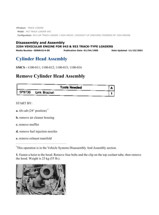
- 1. Product: TRACK LOADER Model: 943 TRACK LOADER 04Z Configuration: 943 LGP TRACK-LOADER / HIGH DRIVE / 04Z00307-UP (MACHINE) POWERED BY 3204 ENGINE Disassembly and Assembly 3204 VEHICULAR ENGINE FOR 943 & 953 TRACK-TYPE LOADERS Media Number -SENR4214-00 Publication Date -01/04/1985 Date Updated -11/10/2001 Cylinder Head Assembly SMCS - 1100-011; 1100-012; 1100-015; 1100-016 Remove Cylinder Head Assembly START BY: a. tilt cab (24° position) * b. remove air cleaner housing c. remove muffler d. remove fuel injection nozzles e. remove exhaust manifold * This operation is in the Vehicle Systems Disassembly And Assembly section. 1. Fasten a hoist to the hood. Remove four bolts and the clip on the top coolant tube; then remove the hood. Weight is 25 kg (55 lb.). 1/8 943 LGP TRACK-LOADER / HIGH DRIVE / 04Z00307-UP (MACHINE) POWERE... 2022/1/13 https://127.0.0.1/sisweb/sisweb/techdoc/techdoc_print_page.jsp?returnurl=/sis...
- 2. 2. Disconnect hose (1) for the air cleaner indicator and from air inlet elbow (3). Disconnect line (2) for the ether starting aid from air inlet elbow (3). 3. Remove air inlet elbow (3) from the cylinder head assembly. 4. Remove tube assembly (4). Loosen hose clamp (5) between the cylinder head assembly and timing gear cover. 5. Remove 22 bolts (6) that hold the cylinder head assembly to the cylinder block. Fasten tool (A) and a hoist to the cylinder head assembly. Remove the cylinder head assembly. Weight is 54 kg (120 lb.). Install Cylinder Head Assembly 1. Clean the surfaces of the cylinder head assembly and the cylinder block that make contact with each other. Check the cylinder head and cylinder block deck for flatness. The overall flatness for both the cylinder block and cylinder head should be 0.15 mm (.006 in.) or less. The maximum allowable for any 152.4 mm (6.00 in.) span is 0.08 mm (.003 in.). Make sure the surfaces are clean and dry. Install a new dry gasket on the cylinder block. 2. Inspect the condition of water ferrule and seal (2). Make a replacement if needed. Put water ferrule and seal (2) in position with the adjusting screw of hose clamp (1) toward the top and approximately 45° to the right of vertical as seen from the front of the engine. 3. Make sure the seal is installed all the way in the counterbore. NOTE: If the plugs in the oil passages in the cylinder head were removed, put 5P3413 Pipe Sealant with Teflon on the threads, and install the plugs in the head. 2/8 943 LGP TRACK-LOADER / HIGH DRIVE / 04Z00307-UP (MACHINE) POWERE... 2022/1/13 https://127.0.0.1/sisweb/sisweb/techdoc/techdoc_print_page.jsp?returnurl=/sis...
- 3. 4. Fasten tool (A) and a hoist to the cylinder head assembly. Put cylinder head assembly (3) in position on the cylinder block. 5. Put 5P3931 Anti-Seize Compound on all the threads of the head bolts. Head Bolt Location And Tightening Sequence 6. Install the head bolts, and tighten as follows: 3/8 943 LGP TRACK-LOADER / HIGH DRIVE / 04Z00307-UP (MACHINE) POWERE... 2022/1/13 https://127.0.0.1/sisweb/sisweb/techdoc/techdoc_print_page.jsp?returnurl=/sis...
- 4. a. Tighten bolts (1) to (18) by number sequence to a torque of 80 ± 14 N·m (60 ± 10 lb.ft.). b. Tighten bolts (1) to (18) by number sequence to a torque of 150 ± 7 N·m (110 ± 5 lb.ft.). c. Tighten bolts (1) to (18) again by number sequence to a torque of 150 ± 7 N·m (110 ± 5 lb.ft.). d. Tighten bolts (19) to (22) by number sequence to a torque of 43 ± 7 N·m (32 ± lb.ft.). 7. Tighten hose clamp (1). 8. Install tube assembly (4). 9. Install the gasket and air inlet elbow (7) on the cylinder head assembly. 10. Connect hose (5) for the air cleaner indicator to air inlet elbow (7). Connect line (6) for the ether starting aid to the air inlet elbow. 11. Fasten a hoist to the hood, and put the hood in position on the machine. Weight of the hood is 25 kg (55 lb.). Install the four bolts that hold the hood in place. Install the clip on the top coolant tube. END BY: a. install muffler b. install exhaust manifold c. install air cleaner housing d. install fuel injection nozzles e. lower cab * * This operation is in the Vehicle Systems Disassembly And Assembly section. 4/8 943 LGP TRACK-LOADER / HIGH DRIVE / 04Z00307-UP (MACHINE) POWERE... 2022/1/13 https://127.0.0.1/sisweb/sisweb/techdoc/techdoc_print_page.jsp?returnurl=/sis...
- 5. Disassemble Cylinder Head Assembly START BY: a. remove cylinder head assembly NOTE: New cylinder head components are effective with the 943 and 953 Loaders with engine serial numbers 10X2188-2205, 10X2210 and 45V32874. New valve springs, retainers, washers and fuel nozzle clamp assemblies are available as a direct replacement for the former components. All new parts must be used together when a replacement is made of the former parts. It is recommended to change all the retainers, valve springs, fuel nozzle clamp assemblies, washers and spacers on a cylinder head or engine at the same time. Do not mix new and used components on the same cylinder head or engine. 1. Fasten a hoist, and put the cylinder head assembly in position on tool (A). Use adapter plates (1) from tooling (A) to hold the head in place. 5/8 943 LGP TRACK-LOADER / HIGH DRIVE / 04Z00307-UP (MACHINE) POWERE... 2022/1/13 https://127.0.0.1/sisweb/sisweb/techdoc/techdoc_print_page.jsp?returnurl=/sis...
- 6. 2. Put the valves under compression with tool (C). 3. Remove the locks from the valves. 4. Remove tool (C), retainer, spring, washer and valve from the cylinder head. Put identification marks on the valve as to its location in the cylinder head. 5. There is an earlier and later valve spring used. The earlier spring, a 9N3617, has a 4.877 mm (.1920 in.) wire diameter and an outside coil diameter of 36.6 mm (1.44 in.). The later spring, a 1W4259, has a 5.232 mm (.2059 in.) wire diameter and an outside coil diameter of 39.6 mm (1.56 in.). Check the valve spring force with tool (B). The minimum spring force of a 9N3617 Spring (used) is 191 N (43 lb.) at a length (height) of 42.04 mm (1.655 in.). The spring force of a new 9N3617 Spring is 222 ± 22 N (50 ± 5 lb.). The length (height) is the same as the used spring. The minimum spring force of a used 1W4259 Spring is 187 N (42 lb.) at a length height of 45.8 mm (1.80 in.). The spring force of a new 1W4259 Spring is 216 ± 22 N (49 ± 5 lb.) when the height is the same as above. For additional information, see Guidelines For Reusable Parts - Valve And Valve Springs Specifications, Form No. 8034-03. Also see Guideline For Reusable Parts And Salvage Operation, Form No. SEBF8002. 6. Do Steps 2 through 5 for the remainder of the valves. 7. Remove the valve seat inserts with tooling (D). 8. Inspect valve guides for wear with tooling (E) or (F). Measure both ends of the valve guide. The diameter of a new valve guide bore is 9.512 ± .013 mm (.3745 ± .0005 in.). The maximum 6/8 943 LGP TRACK-LOADER / HIGH DRIVE / 04Z00307-UP (MACHINE) POWERE... 2022/1/13 https://127.0.0.1/sisweb/sisweb/techdoc/techdoc_print_page.jsp?returnurl=/sis...
- 7. permissible diameter is 9.550 mm (.3760 in.). Any valve guide worn beyond the maximum permissible tolerance must be replaced or knurled. Assemble Cylinder Head Assembly 1. Clean and remove burrs and all foreign material from the valve seat bores. 2. Lower the temperature of the valve seat inserts, and install them with tooling (A). NOTICE Do not make the diameter of the extractor [part of tooling (A)] in valve seat insert larger when the insert is installed in the cylinder head. 3. Grind the valve inserts according to specifications given in Engine Specifications. Use tooling (D) and Special Instructions, Form No. SMHS8319 to measure the valve seat height. 7/8 943 LGP TRACK-LOADER / HIGH DRIVE / 04Z00307-UP (MACHINE) POWERE... 2022/1/13 https://127.0.0.1/sisweb/sisweb/techdoc/techdoc_print_page.jsp?returnurl=/sis...
- 8. 4. Put clean engine oil on the valve stem. Install the valve, washer (3), spring (2) and retainer (1) in the cylinder head. 5. Put the valve spring under compression with tool (C). 6. Install the locks on the valve stem with tool (B). Make sure locks (4) are in their correct position on the valve. The locks can be thrown from the valve when tool (C) is released if the locks are not in their correct position on the valve. 7. Remove tool (C) and hit the valve with a rubber hammer to be sure the locks are in their correct position. 8. Do Steps 4 through 7 for the remainder of the valves. END BY: a. install cylinder head assembly 8/8 943 LGP TRACK-LOADER / HIGH DRIVE / 04Z00307-UP (MACHINE) POWERE... 2022/1/13 https://127.0.0.1/sisweb/sisweb/techdoc/techdoc_print_page.jsp?returnurl=/sis...
- 9. Product: TRACK LOADER Model: 943 TRACK LOADER 04Z Configuration: 943 LGP TRACK-LOADER / HIGH DRIVE / 04Z00307-UP (MACHINE) POWERED BY 3204 ENGINE Disassembly and Assembly 3204 VEHICULAR ENGINE FOR 943 & 953 TRACK-TYPE LOADERS Media Number -SENR4214-00 Publication Date -01/04/1985 Date Updated -11/10/2001 Valve Lifters SMCS - 1209-010 Remove And Install Valve Lifters START BY: a. remove cylinder head assembly 1. Remove valve lifters (1) from the cylinder block with tool (A). Put identification marks on the lifters as to their location in the cylinder block. 2. Put 8T2998 Lubricant on the lifter face that makes contact with the camshaft. 1/2 943 LGP TRACK-LOADER / HIGH DRIVE / 04Z00307-UP (MACHINE) POWERE... 2022/1/13 https://127.0.0.1/sisweb/sisweb/techdoc/techdoc_print_page.jsp?returnurl=/sis...
- 10. 3. Install the valve lifters in the cylinder block with tool (A). Install the lifters in their original locations. New valve lifters can be mixed. END BY: a. install cylinder head assembly 2/2 943 LGP TRACK-LOADER / HIGH DRIVE / 04Z00307-UP (MACHINE) POWERE... 2022/1/13 https://127.0.0.1/sisweb/sisweb/techdoc/techdoc_print_page.jsp?returnurl=/sis...
- 11. Product: TRACK LOADER Model: 943 TRACK LOADER 04Z Configuration: 943 LGP TRACK-LOADER / HIGH DRIVE / 04Z00307-UP (MACHINE) POWERED BY 3204 ENGINE Disassembly and Assembly 3204 VEHICULAR ENGINE FOR 943 & 953 TRACK-TYPE LOADERS Media Number -SENR4214-00 Publication Date -01/04/1985 Date Updated -11/10/2001 Fan SMCS - 1356-011; 1356-012 Remove Fan NOTE: The battery was removed for better photo illustration only. 1. Loosen fan belt tightener (1), and move fan belt (2) off the pulley. 2. Remove both halves of fan guard (3) from the radiator guard. 1/3 943 LGP TRACK-LOADER / HIGH DRIVE / 04Z00307-UP (MACHINE) POWERE... 2022/1/13 https://127.0.0.1/sisweb/sisweb/techdoc/techdoc_print_page.jsp?returnurl=/sis...
- 12. NOTICE Use extra care not to damage the radiator or oil cooler core when the fan is removed. 3. Remove six bolts, nuts and washers (4). Pull the fan and adapter off the bearing and O-ring seal on the fan drive. Remove fan (5) out of the right side of the machine. Weight is 20 kg (45 lb.). Install Fan 1. Put fan (1) in position on the fan drive through the opening on the right side of the machine as shown. Install the six bolts, nuts and washers that hold the fan in position on the fan drive. 2. Install both halves of fan guard (2) on the radiator guard. 2/3 943 LGP TRACK-LOADER / HIGH DRIVE / 04Z00307-UP (MACHINE) POWERE... 2022/1/13 https://127.0.0.1/sisweb/sisweb/techdoc/techdoc_print_page.jsp?returnurl=/sis...
- 13. 3. Put fan belt (3) in position on the pulleys on the crankshaft, fan drive and fan belt tightener (4). 4. Adjust the fan belt. See the V-Belt Tension Chart that follows. When the fan belt tension is correct, tighten the bolt in fan belt tightener (4). 3/3 943 LGP TRACK-LOADER / HIGH DRIVE / 04Z00307-UP (MACHINE) POWERE... 2022/1/13 https://127.0.0.1/sisweb/sisweb/techdoc/techdoc_print_page.jsp?returnurl=/sis...
- 14. Product: TRACK LOADER Model: 943 TRACK LOADER 04Z Configuration: 943 LGP TRACK-LOADER / HIGH DRIVE / 04Z00307-UP (MACHINE) POWERED BY 3204 ENGINE Disassembly and Assembly 3204 VEHICULAR ENGINE FOR 943 & 953 TRACK-TYPE LOADERS Media Number -SENR4214-00 Publication Date -01/04/1985 Date Updated -11/10/2001 Fan Belts SMCS - 1357-010 Remove And Install Fan Belts 1. Remove bolts (1), and move fan adapter (2) and the fan clear of the fan drive. NOTE: The radiator and guard were removed for better photo illustration. 2. Loosen bolts and nut (3) on the alternator, bolts (4) on the belt tightener, and the nuts on belt tightener (5) for the air conditioner compressor. Remove the fan belts. NOTE: When a replacement of one belt in a V-belt set is necessary, a replacement of the complete set should be made. 3. Install the fan belts on the engine. Adjust the fan belts. See the V-Belt Tension Chart at the bottom of the page. Tighten bolts (3) and (4) and the locknut on belt tightener (5) after the belts are adjusted. NOTE: When the tension on a V-belt set is measured, measure the belt farthest from the engine block. 1/2 943 LGP TRACK-LOADER / HIGH DRIVE / 04Z00307-UP (MACHINE) POWERE... 2022/1/13 https://127.0.0.1/sisweb/sisweb/techdoc/techdoc_print_page.jsp?returnurl=/sis...
- 15. 4. Put fan adapter (2) and the fan in position on the fan drive, and install the bolts that hold it in place. 2/2 943 LGP TRACK-LOADER / HIGH DRIVE / 04Z00307-UP (MACHINE) POWERE... 2022/1/13 https://127.0.0.1/sisweb/sisweb/techdoc/techdoc_print_page.jsp?returnurl=/sis...
- 16. Product: TRACK LOADER Model: 943 TRACK LOADER 04Z Configuration: 943 LGP TRACK-LOADER / HIGH DRIVE / 04Z00307-UP (MACHINE) POWERED BY 3204 ENGINE Disassembly and Assembly 3204 VEHICULAR ENGINE FOR 943 & 953 TRACK-TYPE LOADERS Media Number -SENR4214-00 Publication Date -01/04/1985 Date Updated -11/10/2001 Fan Drive SMCS - 1359-011; 1359-012; 1359-015; 1359-016 Remove Fan Drive 1. Loosen the bolts in belt tightener (1) so the fan belts can be removed from the fan drive. 2. Remove bolts (2) that hold the adapter to the fan drive. Move the adapter and fan clear of the fan drive. 3. Remove the belts from the fan drive. NOTE: The radiator guard was removed for better photo illustration only. 4. Remove bolts (3), and remove fan drive (4). Install Fan Drive 1/4 943 LGP TRACK-LOADER / HIGH DRIVE / 04Z00307-UP (MACHINE) POWERE... 2022/1/13 https://127.0.0.1/sisweb/sisweb/techdoc/techdoc_print_page.jsp?returnurl=/sis...
- 17. 1. Put fan drive (1) in position on the timing gear cover, and install the bolts that hold it in place. 2. Put fan belts (2) in position on the fan drive pulley. 3. Put adapter (3) for the fan in position on the fan drive, and install the bolts that hold it in place. 4. Adjust the fan belt tension. See Fan Belt Removal And Installation for the correct belt tension. Disassemble Fan Drive START BY: a. remove fan drive 1. Remove bolts (1), the lock and washer (2) from the bracket assembly. 2. Remove hub (3) and the pulley from the bracket assembly. 2/4 943 LGP TRACK-LOADER / HIGH DRIVE / 04Z00307-UP (MACHINE) POWERE... 2022/1/13 https://127.0.0.1/sisweb/sisweb/techdoc/techdoc_print_page.jsp?returnurl=/sis...
- 18. 3. Remove bearing (4), the spacer and other bearing from the hub. 4. Turn the hub and pulley over, and remove seal (5) from the hub. 5. Remove spacer (6) from the bracket assembly. Assemble Fan Drive 1. Install spacer (1) on the bracket assembly. 3/4 943 LGP TRACK-LOADER / HIGH DRIVE / 04Z00307-UP (MACHINE) POWERE... 2022/1/13 https://127.0.0.1/sisweb/sisweb/techdoc/techdoc_print_page.jsp?returnurl=/sis...
- 19. 2. Use tooling (A) to install the lip-type seal in the hub with the lip out as shown. Put clean grease on the lip of the seal. 3. Turn the hub and pulley over, and install bearing (3), spacer (4) and bearing (2) in the hub. 4. Install hub (7) and the pulley on the bracket assembly. 5. Put washer (5) and lock (6) in position on the bracket assembly, and install the two bolts that hold the washer in place. Bend the ends of the lock over the bolt heads. 6. Use a grease gun to fill the fan drive with 5P960 Multipurpose Type Grease. END BY: a. install fan drive 4/4 943 LGP TRACK-LOADER / HIGH DRIVE / 04Z00307-UP (MACHINE) POWERE... 2022/1/13 https://127.0.0.1/sisweb/sisweb/techdoc/techdoc_print_page.jsp?returnurl=/sis...
- 20. Product: TRACK LOADER Model: 943 TRACK LOADER 04Z Configuration: 943 LGP TRACK-LOADER / HIGH DRIVE / 04Z00307-UP (MACHINE) POWERED BY 3204 ENGINE Disassembly and Assembly 3204 VEHICULAR ENGINE FOR 943 & 953 TRACK-TYPE LOADERS Media Number -SENR4214-00 Publication Date -01/04/1985 Date Updated -11/10/2001 Radiator SMCS - 1353-011; 1353-012 Remove Radiator START BY: a. remove muffler 1. Remove the four bolts that hold the tube for the air cleaner to the hood. Remove the clip that holds the top radiator tube to the hood. Fasten nylon straps and a hoist to hood (1). Remove the four bolts that hold the hood in place, and remove the hood. The weight of the hood for the 943 is 25 kg (55 lb.). The weight of the hood for the 953 is 30 kg (66 lb.). 1/7 943 LGP TRACK-LOADER / HIGH DRIVE / 04Z00307-UP (MACHINE) POWERE... 2022/1/13 https://127.0.0.1/sisweb/sisweb/techdoc/techdoc_print_page.jsp?returnurl=/sis...
- 21. 2. Fasten a nylon strap and hoist to grille (3). Remove brackets (2) and grille (3). 3. Disconnect the wires from lights (4). Remove lights (4) and guards (5) from the guard on the radiator. Disconnect the wire for lights and back-up alarm at the bottom of the guard. 4. Install tooling (A) on the guard, and fasten a hoist as shown. Remove bolts (6). 5. Remove bolts (8) from both sides of guard (7). Remove guard (7) from the radiator guard. The weight of the guard for the 943 is 29 kg (65 lb.). The weight of the guard for the 953 is 34 kg (75 lb.). 6. Drain the coolant from the radiator. 7. Remove guard (9) below the radiator. 2/7 943 LGP TRACK-LOADER / HIGH DRIVE / 04Z00307-UP (MACHINE) POWERE... 2022/1/13 https://127.0.0.1/sisweb/sisweb/techdoc/techdoc_print_page.jsp?returnurl=/sis...
- 22. 8. Remove two bolts and spacers (12). Loosen hose clamp (10), and disconnect hose (11) from the tube. 9. Loosen hose clamp (13), and disconnect the top hose from the radiator. 10. Remove six bolts (14) from the channel assembly. Remove two bolts (15) from the clamp. 11. Remove bolts (19), and move hydraulic oil cooler (20) away from the radiator. NOTICE Tooling (A) must be fastened to frame (16) not to the radiator core. 12. Fasten tooling (A) and a hoist to frame (16). 13. Remove the clips that hold wire (17) and oil line (18) to frame (16). 14. Carefully remove frame (16) and the radiator as a unit. Weight is approximately 54 kg (120 lb.). Put the frame and radiator on blocks to prevent damage to the lower radiator hose. 3/7 943 LGP TRACK-LOADER / HIGH DRIVE / 04Z00307-UP (MACHINE) POWERE... 2022/1/13 https://127.0.0.1/sisweb/sisweb/techdoc/techdoc_print_page.jsp?returnurl=/sis...
- 23. 15. Remove tooling (A) from frame (16), and fasten tooling (A) to the radiator core. Fasten a hoist to tooling (A). 16. Remove the two bolts and spacers from the bottom of the radiator core. Remove bolts (21) and plate (22) from the frame. Remove the radiator core from the frame. Install Radiator 1. Fasten tooling (A) and a hoist to the radiator core. Put the radiator core in position in frame (1). Install the two bolts and spacers in the bottom of the radiator. Install the plate and the remainder of the bolts that hold the radiator core to the frame. 2. Remove tooling (A) from the radiator core, and install tooling (A) on frame (1), and fasten a hoist. 3. Put the radiator and frame (1) in position in the radiator guard. Put the clips on the oil line to the oil cooler in position on frame (1), and install the bolts that hold the clips in place. Put the wire for the left light and clips in position on frame (1), and install the bolts that hold the clips in place. 4/7 943 LGP TRACK-LOADER / HIGH DRIVE / 04Z00307-UP (MACHINE) POWERE... 2022/1/13 https://127.0.0.1/sisweb/sisweb/techdoc/techdoc_print_page.jsp?returnurl=/sis...
- 24. Suggest: For more complete manuals. Please go to the home page. https://www.ebooklibonline.com If the above button click is invalid. Please download this document first, and then click the above link to download the complete manual. Thank you so much for reading
- 25. 4. Install eight bolts (2) that hold the frame for the radiator core to channel (3). 5. Connect the top radiator hose to the radiator, and tighten hose clamp (4). 6. Connect the bottom radiator hose to tube (5), and tighten hose clamp (6). 7. Install two spacers and bolts (7) that hold the frame for the radiator core to the radiator guard. 8. Install guard (8) below the radiator. 9. Put hydraulic oil cooler (10) in position, and install the bolts that hold it in place. 10. Fasten tooling (A) and a hoist to guard (9). Put guard (9) in position on the radiator guard, and install the bolts in holes (11). 5/7 943 LGP TRACK-LOADER / HIGH DRIVE / 04Z00307-UP (MACHINE) POWERE... 2022/1/13 https://127.0.0.1/sisweb/sisweb/techdoc/techdoc_print_page.jsp?returnurl=/sis...
- 26. 11. Install bolts (12) in both sides of the guard. Remove the hoist and tooling (A) from the guard. 12. Install guards (13) for the lights on the radiator guard. 13. Connect the wires to lights (14), and install the lights in guards (13). Connect the wires for the lights and back-up alarm at the bottom of the guard. 14. Install the grille. 15. Fasten nylon straps and a hoist to hood (15). Put the hood in position on the machine, and install the four bolts that hold it in place. 16. Install the clip that holds the top radiator tube to the hood. Put the tube for the air cleaner in position on the hood, and install the four bolts that hold it in place. 17. Fill the radiator to the correct level with coolant. 6/7 943 LGP TRACK-LOADER / HIGH DRIVE / 04Z00307-UP (MACHINE) POWERE... 2022/1/13 https://127.0.0.1/sisweb/sisweb/techdoc/techdoc_print_page.jsp?returnurl=/sis...