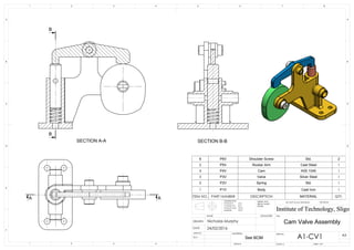
This document is an exploded view assembly drawing of a cam valve assembly with bill of materials. The assembly consists of 6 main parts: a shoulder screw, rocker arm, cam, valve, spring, and body. The drawing shows the parts in their exploded positions with labels and dimensions. The bill of materials lists each part number, name, material, and quantity.
1. AA
B
B
SECTION A-A SECTION B-B
Cam Valve Assembly
See BOM
ITEM NO. PART NUMBER DESCRIPTION MATERIAL QTY.
6 P6V Shoulder Screw Std. 2
5 P5V Rocker Arm Cast Steel 1
4 P4V Cam AISI 1040 1
3 P3V Valve Silver Steel 1
2 P2V Spring Std. 1
1 P1V Body Cast Iron 1
D
E
F
C
1 2 3 4
B
A
321 5
C
D
4 6 7 8
A
B
A1-CV1
Institute of Technology, Sligo
24/02/2016
WEIGHT:
A3
SHEET 1 OF 1SCALE:1:5
DWG NO.
TITLE:
REVISIONDO NOT SCALE DRAWING
MATERIAL:
SIGNATURENAME
Q.A
D
E
F
C
1 2 3 4
B
A
321 5
C
D
4 6 7 8
A
B
Institute of Technology, Sligo
TOLERANCES:
0 PLACE X 0.2
1 PLACE X.X 0.1
2 PLACE X.XX 0.01
ANGLES: 0.5
A3
SHEET 1 OF 1SCALE:1:5
DWG NO.
TITLE:
DEBUR AND
BREAK SHARP
EDGES
APPV'D
DATE
Nicholas MurphyDRAWN