SlideShare a Scribd company logo
1 of 14
Download to read offline
User's Manual
Benutzerhandbuch
Mode d’emploi
Manual del usuario
Manuale dell’utente
Manual do Utilizador
安裝說明書
用戶手冊
ユーザーズマニュアル
Руководство пользователя
kullanıcı elkitabı
(EEE Yönetmeliğine Uygundur)
คู่มือการใช้
© 2020 Thermaltake Technology Co., Ltd. All Rights Reserved. 2020.01
All other registered trademarks belong to their respective companies. www.thermaltake.com
Tested To Comply
With FCC Standards
FOR HOME OR OFFICE USE
Picture is for reference only
view 51 TG ARGB
Join Tt Community To Receive Benefits
Tt LCS-Liquid Cooling Support Certification
TT Premium
Dear Valued Customer,
Thank you for choosing Thermaltake.
As a new user we value your thoughts and opinions and
your feedback is important to us. We at Thermaltake
would like to use this opportunity to invite you to join our
Community Forums. Register today to start enjoying the
full benefits of our community.
Benefits of being a member:
Quick and responsive user support
Receive help and advice with new builds
Keep up to date with new product releases
Share your thoughts and builds with the community
Enter monthly contests and giveaways
Tt LCS Certified is a Thermaltake exclusive certification
applied to only products that pass the design and
hardcore enthusiasts standards that a true LCS chassis
should be held to. The Tt LCS certification was created
so that we at Thermaltake can designate to all power
users which chassis have been tested to be best
compatible with extreme liquid cooling configurations to
ensure you get the best performance from the best
features and fitment.
Brand official website
http://www.thermaltake.com/
Global Facebook
https://www.facebook.com/ThermaltakeInc
TT Premium
To continue achieving the corporate mission of delivering the
perfect user experience, Thermaltake developed “TT Premium”
with the essence of combining supreme quality products with a
new logo design. TT Premium is far more than just a guarantee
of quality. Behind the name, it represents the passion in DIY,
Modding and Thermaltake’s desire to be the most innovative
brand in the PC hardware market. To satisfy the demand of the
high-end PC users, TT Premium follows its core values of
Excellent Quality, Unique Design, Diverse Combinations and
Boundless Creativity to provide a high performance PC product
for every enthusiast. http://ttpremium.com
Taiwan Facebook
http://www.facebook.com/ThermaltakeTW
Global community forums
http://community.thermaltake.com
Chapter 1. Product Introduction
Specification
Accessory
Warning and Notice
1.0
1.1
1.2
01
02
03
Contents
Chapter 2. Installation Guide
2.0
2.1
2.2
2.3
2.4
2.5
2.6
2.7
2.8
2.9
Side Panels Disassembly
Power Supply Unit (PSU) Installation
Motherboard Installation
3.5" & 2.5" HDD Installation
PCI Card Installation
RGB Switch Mode
Air Cooling Installation
Liquid Cooling Installation
Liquid Cooling Installation - 200mm Fan
Pump Installation
05
06
07
08
10
12
13
14
15
16
Chapter 3. Leads Installation
Case LED Connection
USB 3.0 Connection
Audio Connection
3.1
3.2
3.3
17
17
17
Chapter 4. Other
4.1
4.2
23
24
Thermaltake Power Supply Series (Optional)
Tt RGB Plus Ecosystem
*Picture for reference only
*Information in the user manual is subject to change without notice
Specification Accessory
8
Figure Parts Name Q'ty
2
4
24
1
8
10
1
Used for
2
Full Tower
Radiator Support
Case Type
Dimension (H*W*D)
2.5” x 2 or 3.5” x 2 (With HDD Rack) ;
2.5” x 2 (With HDD Bracket)
550 x 315 x 525 mm (21.65 x 12.4 x 20.67 inch)
Side Panel Tempered Glass x 3 (4mm thickness)
Material SPCC
Cooling System
Front (intake) :
200 x 200 x 30 mm Addressable RGB fan (600rpm, 24dBA) x 2
Rear (exhaust) :
120 x 120 x 25 mm Addressable RGB fan (1000rpm, 27.2dBA)
Drive Bays
- Accessible
- Hidden
Expansion Slots 8
Motherboards
6.7” x 6.7” (Mini ITX), 9.6” x 9.6” (Micro ATX),
12” x 9.6” (ATX), 12” x 10.5” (CEB)
I/O Port Type-C x 1, USB 3.0 x 2, USB 2.0 x 2, HD Audio x 1
PSU Standard PS2 PSU (optional)
Fan Support
Front: 3 x 120mm, 3 x 140mm, 2 x 200mm
Top: 3 x 120mm, 3 x 140mm, 2 x 200mm
Rear: 1 x 120mm
Right: 3 x 120mm, 2 x 140mm
Bottom: 3 x 120mm (Without Water Pump)
Front: 1 x 360mm, 1 x 280mm
Top: 1 x 360mm, 1 x 280mm
Right: 1 x 360mm, 1 x 280mm
Bottom: 1 x 360mm (Without Water Pump)
Clearance
CPU cooler height limitation: 175mm
VGA length limitation: 300mm (With Water Pump)
440mm (Without Water Pump)
PSU length limitation: 200mm
MB, 3.5” HDD
Power
MB Stand-off
Cable Management
Motherboard Alarm
2030 Fan
Backup
Backup
2.5” HDD / SSD
Backup
Stand-off #6-32 x 6.5mm
Screw #6-32 x 6mm
Screw #6-32 x 6mm
Screw M3 x 5mm
Cable ties
Buzzer
Thumb Screw #6-32 x 5mm
Rubber
Screw #6-32 x 38mm
Nut setter
16
Velcro cable tip 3
MB Signal bridge cable
(ASUS / MSI) 1
MB Signal bridge cable
(GIGABYTE) 1
Cable Management
LED Signal Sync
LED Signal Sync
1 2
Warning and Notice
<175 mm
<300 mm
Warning!!
CPU Cooler Height Limitation:
Please ensure that your CPU cooler does NOT exceed 175mm (6.89 inches) height.
VGA (Add-on card) Length Limitation:
Please ensure that your VGA (Add-on card) does NOT exceed 300mm (11.81 inches) length.
Warnung!!
CPU-Kühler Höhenbeschränkung:
Bitte stellen Sie sicher, dass Ihr CPU-Kühler 175 mm (6,89 Zoll) Höhe nicht überschreitet.
VGA (Add-on-Karte) Längenbeschränkung:
Bitte stellen Sie sicher, dass Ihre VGA (Add-on-Karte) 300 mm (11,81 Zoll) Länge nicht
überschreitet.
Avertissement !
Limite de hauteur du ventilateur de CPU :
Vérifiez que la hauteur du ventilateur de CPU ne dépasse pas 175 mm.
Limite de longueur de la carte (complémentaire) VGA :
Vérifiez que la longueur de votre carte (complémentaire) VGA ne dépasse pas 300 mm
Precaución
Limitación de altura del refrigerador de CPU:
Asegúrese de que la altura de su refrigerador de CPU no excede los 175 mm (6,89 pulgadas).
Limitación de longitud de la tarjeta de vídeo (adicional):
Asegúrese de que la longitud de su tarjeta de vídeo (adicional) no excede los 300 mm (11,81
pulgadas).
Attenzione!
Limitazione altezza dissipatore CPU:
Assicurarsi che l’altezza del dissipatore CPU NON superi 175 mm (6,89 pollici).
Limitazione lunghezza VGA (scheda aggiuntiva):
Assicurarsi che la lunghezza del VGA (scheda aggiuntiva) NON superi 300 mm (11,81 pollici).
Atenção!!
Limite de altura para o dissipador do CPU:
O limite de altura para o dissipador do CPU é 175 mm (6,89 polegadas).
CPU 冷卻器的高度限制:
請確保 CPU 冷卻器的高度不超過 175 mm (6.89 英吋)。
VGA (附加介面卡) 的長度限制:
請確保 VGA (附加介面卡) 的長度不超過 300 mm (11.81 英吋)。
CPU 散热器高度限制:
请确保 CPU 散热器的高度不超过 175 mm(6.89 英寸)。
VGA(附加卡)长度限制:
请确保 VGA(附加卡)的长度不超过 300 mm(11.81 英寸)。
CPUクーラーの高さ制限:
CPUクーラーの高さが175mmを超えていないことを確認してください。
VGA(アドオンカード)の長さ制限:
VGA(アドオンカード)の長さが300mmを超えていないことを確認してください。
Ограничение по высоте охладителя ЦП
Убедитесь, что высота охладителя ЦП (центрального процессора) НЕ превышает 175 м
(6,89 дюйма).
Ограничение по длине видеокарты VGA (плата расширения)
Убедитесь, что длина видеокарты VGA (плата расширения) НЕ превышает 300 мм
(11,81 дюйма).
CPU Soğutucu Yükseklik Sınırlaması:
Lütfen CPU soğutucunuzun yüksekliğinin 175mm’yi (6,89 inç) GEÇMEDİĞİNDEN emin olun.
VGA (Eklenti kartı) Uzunluk Sınırlaması:
Lütfen VGA’nızın (Eklenti kartı) uzunluğunun 300mm’yi (11,81 inç) GEÇMEDİĞİNDEN emin
olun.
Limite de comprimento para VGA (placa gráfica):
O limite de comprimento para VGA (placa gráfica) é 300 mm (11,81 polegadas).
警告!!
警告!!
警告
Внимание!
Uyarı!!
คำเตือน!!
ขีดจำกัดความสูงสำหรับฮีตซิงก์ของ CPU:
ขีดจำกัดความสูงสำหรับฮีตซิงก์ของ CPU คือ 175 มม. (6.89 นิ้ว)
ขีดจำกัดความยาวสำหรับ VGA (การ์ดแสดงผล):
ขีดจำกัดความยาวสำหรับ VGA (การ์ดแสดงผล) คือ 300 มม. (11.81 นิ้ว)
3 4
Side Panels Disassembly
English /
Remove the screws on the back of the chassis,
and open the side panel
Deutsch /
Entfernen Sie die Schrauben auf der Rückseite
des Gehäuses und öffnen Sie das Seitenteil
Français /
Enlevez les vis à l’arrière du châssis et ouvrez le
panneau latéral
Español /
Extraiga los tornillos de la parte posterior de la
caja y abra el panel lateral
Italiano /
Rimuovere le viti sulla parte posteriore dello
chassis e aprire il pannello laterale
Português/
Remova os parafusos na parte de trás da caixa e
abra o painel lateral
繁體中文 /
移除機殼後方螺絲,將側窗打開
日本語 /
シャーシ背面のねじを取り外し、サイドパネ
ルを開きます
Русский /
Открутите винты на задней стенке корпуса
и откройте боковую панель
简体中文 /
卸除机壳后方螺丝,将侧窗打开
Türkçe /
Kasanın arkasındaki vidaları çıkarın ve yan
paneli açın
ภาษาไทย /
ถอดสกรูที่ด้านหลังของแชสซีส์
แล้วเปิดแผงด้านข้าง
Power Supply Unit (PSU) Installation
English /
Deutsch /
Français /
Placez l’alimentation dans la position appropriée.
Español /
Instale la PSU en la ubicación correcta.
Italiano /
Place the PSU in proper location.
Platzieren Sie das Netzteil in der richtigen Position.
Posizionare la PSU in modo corretto.
Português/
Coloque o PSU na sua devida posição.
繁體中文 /
简体中文 /
日本語 /
Русский /
Установите блок питания в надлежащее место.
Türkçe /
將電源供應器放在正確的位置
将电源供应器放在正确的位置
PSUを適切なロケーションに取り付けます。
PSU’yu, uygun konuma yerleştirin.
ภาษาไทย /
วาง PSU ในตำแหน่งที่เหมาะสม
5 6
Motherboard Installation
English /
1.Lay down the chassis.
2.Install the motherboard in proper location and
secure it with screws.
Deutsch /
1.Legen Sie das Gehäuse auf die Seite.
2.Installieren Sie die Hauptplatine in ihrer
vorgesehenen Position und sichern Sie sie mit
Schrauben.
Français /
1.Posez à plat le châssis.
2.Installez la carte mère dans l'endroit approprié et
sécurisez-la avec des vis.
Español /
1. Tumbe el chasis.
2. Instale la placa madre en la ubicación adecuada
y asegúrela con tornillos.
Italiano /
1.Poggiare lo chassis.
2.Installare la scheda madre nella posizione
appropriata e fissarla con le viti.
Português/
1. Deixe a caixa.
2. Instale a motherboard no local adequado e
aparafuse.
繁體中文 /
1. 將機殼平放。
2. 將主機板放置在合適的位置並用零件包中之螺
絲固定。
日本語 /
1.シャーシを下に置きます。
2.マザーボードを適切な場所に取り付け、ねじで
固定します。
Русский /
1. Раскройте системный блок.
2. Установите материнскую плату в
надлежащее место и закрепите ее винтами.
简体中文 /
1. 放平机箱。
2. 在合适的位置安装主板并以螺丝安全固定。
Türkçe /
1.Kasayı yan yatırın.
2.Ana kartı uygun konuma takın ve vidalarla
sabitleyin.
ภาษาไทย /
1.วางแชสซีส์นอนลง
2.ติดตั้งเมนบอร์ดในตำแหน่งที่เหมาะสม
แล้วขันสกรูยึดให้แน่น
3.5" & 2.5" HDD Installation
TypeA
3.5” HDD SSD / 2.5” HDD
7 8
English / 繁體中文 /
1. Pull the HDD tray out. 1. 將硬碟托盤取出
2. Place the 2.5” or 3.5” hard drive on the tray 2. 將2.5”或3.5”硬碟放置在硬碟托盤上,用螺絲固
and secure it with screws. 定硬碟
3. Slide the HDD tray back to the HDD cage. 3. 將硬碟托盤放回硬碟磁架中
Deutsch / 简体中文 /
1. Ziehen Sie den HD-Schacht heraus. 1. 将硬盘托盘取出
2. Montieren Sie die 2,5 oder 3,5 Zoll Festplatte 2. 将2.5”或3.5”硬盘放置在硬盘托盘上,
im Schacht und sichern Sie sie mit Schrauben. 用螺丝固定硬盘
3. Schieben Sie den Schacht wieder in den 3. 将硬盘托盘放回硬盘磁架中
Festplattenkäfig.
日本語 /
Français / 1.HDDトレイを引き出して外します。
1. Enlevez le boîtier du disque dur. 2.2.5インチHDD、SSD もしくは 3.5インチ
2. Placez le disque dur de 2,5” ou de 3,5” dans le HDDドライブをトレイにネジで固定します。
boîtier et fixez-le avec des vis. 3. HDDトレイをHDDケージに戻します。
3. Refaites glisser le boîtier du disque dur dans
la cage de disques durs. Русский /
1. Вытяните лоток для жестких дисков.
Español / 2. Установите 2,5- или 3,5-дюймовый жесткий
1. Extraiga la bandeja del disco duro. диск в лоток и закрепите его винтами.
2. Coloque el disco duro de 2’5 ó 3'5” en la 3. Установите лоток для жестких дисков
bandeja y fíjelo con los tornillos. обратно в каркас.
3. Vuelva a meter la bandeja del disco duro en su
hueco. Türkçe /
1. HDD tepsisini dışarı çekin.
Italiano / 2. 2,5” veya 3,5” sabit disk sürücüsünü tepsinin
1. Estrarre il vano HDD. üzerine yerleştirin ve vidalarla sabitleyin.
2. Posizionare il disco fisso da 2,5” o 3,5” nel 3. HDD tepsisini HDD kafesine geri yerleştirin.
vano e fissarlo con le viti.
3. Fare scorrere l’HDD indietro verso la struttura ภาษาไทย /
a gabbia HDD. 1. ดึงถาด HDD ออกมา
2. วางฮาร์ดไดร์ฟขนาด 2.5” หรือ 3.5”
Português / ลงบนถาดแล้วขันสกรูยึดให้แน่น
1. Puxe a bandeja do disco rígido para fora. 3. เลื่อนถาด HDD กลับเข้าในโครง HDD
2. Coloque o disco rígido de 2,5” ou 3,5” na
bandeja e fixe com parafusos.
3. Deslize a bandeja do disco rígido de volta para
a caixa do disco rígido.
TypeB TypeC
SSD / 2.5” HDD SSD / 2.5” HDD PCI Card Installation
TypeA
9 10
(Optional) Vertical GPU installation
※Riser Cable is not included
TypeB
RGB Switch Mode
I/O Port
How to connect MB
Flow Mode
Wave Mode
RGB Lighting
Radar Mode
Breath Mode
Single Color
Full Lighted Mode
Light Off
Mode 2
Mode 1
Mode 3 (Single Color)
Mode 4~10 (Red, Yellow, Green, Cyan, Blue, White, Purple)
Mode 11~18 (RGB, Red, Yellow, Green, Cyan, Blue, White, Purple)
Mode 20~26 (Red, Yellow, Green, Cyan, Blue, White, Purple)
Mode 19
Mode 27
※ Long press on RGB button for 3 seconds, fan will blink twice which
now are controlled by MB software. And vice versa.
Aura Addressable Strip Header(s) Addressable RGB LED Header(s) AORUS RGB Fusion with Digital LEDs
ASUS GIGABYTE
JRGB-strip Header(S)
MSI
MSI
+5V D G
JRAINBOW
G
ASROCK
11 12
Air Cooling Installation Liquid Cooling Installation
Front
120mm x 3
or
140mm x 3
or
200mm x 2
Bottom
120mm x 3
120mm x 3
or
140mm x 2
Top
360 x 30 mm
or
280 x 55 mm
Bottom
360 x 30 mm Front
360 x 30 mm
or
280 x 55 mm
Right
360 x 64 mm
or
280 x 55 mm
Top
120mm x 3
or
140mm x 3
or
200mm x 2
Right
120mm x 1
Back
※ The Radiators are recommended to mount inside the chassis.
13 14
Liquid Cooling Installation - 200mm Fan
Radiator 360mm + 200mm Fan
Pump Installation
or
Rubber
15 16
Leads Installation
Leads Installation Guide
A. Case LED Connection / On the front of the case, you can find some LEDs and switch leads. Please consult your
user manual of your motherboard manufacturer, then connect these leads to the panel header on the motherboard.
B. USB 3.0 connection /
1. Make sure your motherboard supports USB 3.0 connection.
2. Connect the USB 3.0 cable to the available USB 3.0 port on your computer.
C. Audio Connection / Please refer to the following illustration of Audio connector and your motherboard user
manual. Please select the motherboard which used AC’97 or HD Audio(Azalia),(be aware of that your audio supports
AC’97 or HD Audio (Azalia)) or it will damage your device(s).
Anschlüsse herstellen
A. Gehäuse-LED-Verbindungen / Auf der Gehäusevorderseite finden Sie einige LEDs und Verbindungen. Bitte
nehmen Sie die Gebrauchsanweisung Ihres Motherboard Herstellers zur Hilfe und schließen Sie diese Verbindungen an
die Panel Header Belegung des Motherboards an.
B. USB 3.0 Anschluss /
1. Stellen Sie sicher, dass Ihre Hauptplatine den USB 3.0 Anschluss unterstützt.
2. Verbinden Sie das USB 3.0 Kabel mit dem USB 3.0 Port auf Ihrem Computer.
C. Audio Anschlüsse / Bitte beachten Sie die folgende Abbildung der Audio Anschlüsse und die Anweisung in der
Gebrauchsanweisung Ihres Motherboards. Bitte wählen Sie das Motherboard, das AC’97 oder HD Audio(Azalia)
verwendet, (achten Sie darauf, dass Ihr Audio AC’97 bzw. HD Audio (Azalia unterstützt)). Andernfalls entstehen schwere
Schäden an Ihrem(n) Gerät(en)!!!
USB 3.0 Connection USB 3.0 Connection
PRESENCE# PRESENCE#
BLACK BLACK
SENSE1_RETURN SENSE1_RETURN
AUD GND AUD GND
SENSE2_RETURN SENSE2_RETURN
YELLOW YELLOW
BROWN BROWN
RED RED
PORT1 R PORT1 R
PORT2 R PORT2 R
PORT1 L PORT1 L
BLUE BLUE
PORT2 L PORT2 L
SENSE_SEND SENSE_SEND
KEY KEY
PURPLE PURPLE
GREEN GREEN
ORANGE ORANGE
BLACK BLACK
AUDIO HD AUDIO Function AUDIO HD AUDIO Function
English
Deutsch
Guide d'installation des fils
A. Connexion des voyants du boîtier / Sur la face avant du boîtier, vous trouverez plusieurs voyants et les fils des
boutons. S'il vous plaît consultez le guide d'utilisateur du fabricant de votre carte mère, puis connectez ces fils aux
onnecteurs sur la carte mère.
B. Connexion USB 3.0 /
1. Vérifiez que votre carte mère prend en charge la connexion USB 3.0.
2. Connectez le câble USB 3.0 au port USB 3.0 disponible sur votre ordinateur.
C. Connexion Audio / S'il vous plaît référez vous à l'illustration suivante du connecteur audio et au guide de l'utilisateur
de votre carte mère. S'il vous plaît sélectionnez une carte mère supportant AC'97 ou HD Audi (Azalia), (faites attention que
votre audio supporte l'AC'97 ou HD Audio (Azalia)) sinon cela pourrait endommager votre matériel.
Guía de Instalación de Cables
A. Conexión del LED de la caja / En la parte frontal de la caja, encontrará algunos LED y cables de interruptores.
Consulte el manual del usuario del fabricante de la placa madre, a continuación conecte estos cables al conector de la placa
madre.
B. Conexión USB 3.0 /
1. Asegúrese de que la placa base admite conexión USB 3.0.
2. Conecte el cable USB 3.0 al puerto USB 3.0 disponible en el equipo.
C. Conexión de Audio / Consulte la siguiente ilustración del conector de Audio y el manual del usuario de la placa madre.
Seleccione la placa madre que utiliza AC’97 o HD Audio (Azalia), (asegúrese de que su audio admite AC’97 o HD Audio
(Azalia)) si no, sus dispositivos resultarán dañados
Français
Español
A A
B B
C C
17 18
Guida di installazione dei contatti
A. Connessione del LED del case / Nella parte anteriore del case, sono presenti alcuni contatti per interruttori e LED.
Consultare il manuale utente del produttore della scheda madre, quindi connettere i contatti alla parte superiore del
pannello sulla scheda madre.
B. Connessione USB 3.0 /
1. Accertarsi che la scheda madre supporti la connessione USB 3.0.
2. Collegare il cavo USB 3.0 alla porta USB 3.0 disponibile sul computer.
C. Connessione Audio / Fare riferimento all’illustrazione riportata di seguito del connettore Audio e al manuale utente
per la scheda madre.Selezionare la scheda madre relativa a AC’97 o HD Audio (Azalia) e considerare che il supporto audio
è compatibile con AC’97 o HD Audio (Azalia); in caso contrario, le periferiche potrebbero venire danneggiate.
Guia de Instalação Eléctrica
A. Ligação do LED da Caixa / Na parte dianteira da caixa pode encontrar alguns LEDs e fios eléctricos. Consulte o
manual de utilizador do fabricante da sua motherboard e ligue os fios à parte superior do painel na motherboard.
B. Ligação USB 3.0 /
1. Certifique-se que a sua motherboard suporta ligação USB 3.0.
2. Ligue o cabo USB 3.0 à porta USB 3.0 disponível no seu computador.
C. Ligação Áudio / Consulte a imagem seguinte do conector Áudio e o manual de utilizador da sua motherboard.
Seleccione a motherboard que utiliza AC’97 ou HD Áudio(Azalia), (verifique se a sua placa de áudio suporta AC’97 ou HD
Áudio(Azalia)) ou irá danificar o(s) seu(s) dispositivo(s).
Italiano
Português
線材安裝說明
A. 機殼LED連接方式 / 在機殼前方的面板後面,可以找到一些LED與開關線材(POWER Switch….),請參考主機板使用說明
書,並將機殼上的線材正確地連接到主機板上,這些線材通常都會印有標籤在上面,如果沒有的話,請找出機殼前方面板上線
材原本的位置以知道正確的來源。
B. USB 3.0 連接 /
1. 請確認主機板是否支援USB 3.0傳輸介面。
2. 連接USB 3.0傳輸線至主機板上的USB3.0接埠。
C. 音效連接 / 請根據下面的音源接頭圖示與主機板使用手冊來連接音效裝置,請確認主機板上的音效裝置是支援AC' 97音效或
是HD音效(Azalia),裝置錯誤可能會導致主機板音效裝置的毀損,某些主機板的音效裝置不會與下方的圖示完全相同,請參酌
主機板使用手冊以得到正確的安裝資訊
线材安装说明
A. 机壳LED连接方式 / 在机壳前方的面板后面,可以找到一些LED与开关线材(POWER Switch….),请参考主板使用说明
书,并将机壳上的线材正确地连接到主板上,这些线材通常都会印有标签在上面,如果没有的话,请找出机壳前方面板上线
材原本的位置以知道正确的来源。
B. USB 3.0 连接 /
1.请确认主板是否支持USB 3.0传输接口。
2.连接USB 3.0传输线至主板上的USB3.0接埠。
音效连接 / 请根据下面的音源接头图示与主板使用手册来连接音效装置,请确认主板上的音效装置是支持AC' 97音效或是
C. HD音效(Azalia),装置错误可能会导致主板音效装置的毁损,某些主板的音效装置不会与下方的图标完全相同,请参酌主
板使用手册以得到正确的安装信息
繁體中文
简体中文
USB 3.0 Connection USB 3.0 Connection
PRESENCE# PRESENCE#
BLACK BLACK
SENSE1_RETURN SENSE1_RETURN
AUD GND AUD GND
SENSE2_RETURN SENSE2_RETURN
YELLOW YELLOW
BROWN BROWN
RED RED
PORT1 R PORT1 R
PORT2 R PORT2 R
PORT1 L PORT1 L
BLUE BLUE
PORT2 L PORT2 L
SENSE_SEND SENSE_SEND
KEY KEY
PURPLE PURPLE
GREEN GREEN
ORANGE ORANGE
BLACK BLACK
AUDIO HD AUDIO Function AUDIO HD AUDIO Function
A A
B B
C C
20
19
Указания по прокладке кабелей
A. Подключение индикаторов корпуса / В передней части корпуса расположены индикаторы и провода выключател
ей. Перед подсоединением этих проводов к монтажной колодке панели на материнской плате изучите руководство
пользователя производителя материнской платы.
B. Подключение USB 3.0 /
1. Убедитесь, что материнская плата поддерживает подключение по стандарту USB 3.0.
2. Подсоедините кабель USB 3.0 к свободному порту USB 3.0 компьютера.
C. Подключение аудиоразъема / См. следующую иллюстрацию аудиоразъема и руководство пользователя материн
ской платы. Выберите материнскую плату, в которой используется кодек AC'97 или HD Audio (Azalia) (убедитесь, что
звуковая плата поддерживает кодек AC'97 или HD Audio (Azalia)). В противном случае можно повредить устройства.
リード線の取り付けガイド
A. ケース LED の接続 / ケース前面には、LEDとスイッチリード線があります。 マザーボードメーカーのユーザーマニュ
アルを参照し、これらのリード線をマザーボードのパネルヘッダに接続してください。
B. USB 3.0 の接続 /
1. お使いのマザーボードがUSB 3.0接続をサポートしていることを確認してください。
2. USB 3.0ケーブルをコンピュータの空いているUSB 3.0ポートに接続します。
C. オーディオ接続 / オーディオコネクタの次の図とマザーボードのユーザーマニュアルを参照してください。AC’97または
HDオーディオ(Azalia)を使用するマザーボードを選択してください(オーディオがAC’97またはHDオーディオ(Azalia)をサポ
ートしていることを確認してください)。サポートしていないと、デバイスが損傷します)。
日本語
Русский
Ara Kablo Kurulum Kılavuzu
A. Kasa ışık bağlantısı / Kasanın ön kısmında bazı ışıklar ve anahtar ara kabloları görebilirsiniz. Lütfen anakart üreticinizin
sağladığı kullanım kılavuzuna bakın ve daha sonra, bu ara kabloları, anakart üzerindeki panel bağlantı noktalarına bağlayın.
B. USB 3.0 Bağlantısı /
1. Ana kartınızın USB 3.0 bağlantısını desteklediğinden emin olun.
2. USB 3.0 kablosunu, bilgisayarınızdaki kullanılabilir USB 3.0 bağlantı noktasına bağlayın.
C. Ses Bağlantısı / Lütfen aşağıdaki Ses konektörü resmine ve anakartınızın kullanım kılavuzuna bakın. Lütfen AC’97 veya
HD Audio(Azalia) spesifikasyonunu kullanan bir anakart seçin (ses sisteminizin AC’97 veya HD Audio (Azalia)
spesifikasyonunu desteklediğini unutmayın); aksi takdirde, aygıt(lar)ınız zarar görür.
คู่มือการติดตั้งสายไฟ
A. การเชื่อมต่อไฟ LED ของเคส / ที่ด้านหน้าของเคส คุณจะเห็นไฟ LED และสายไฟของสวิตซ์
กรุณาศึกษารายละเอียดจากคู่มือผู้ใช้ของผู้ผลิตแผงวงจรหลักของคุณ
จากนั้นให้เชื่อมต่อสายไฟเหล่านี้เข้ากับส่วนหัวของแผงบนแผงวงจรหลัก
B. การเชื่อมต่อ USB 3.0 /
1. ตรวจดูให้แน่ใจว่าแผงวงจรหลักของคุณรองรับการเชื่อมต่อ USB 3.0
2. เชื่อมต่อสาย USB 3.0 เข้ากับพอร์ต USB 3.0 ที่สามารถใช้งานได้บนคอมพิวเตอร์ของคุณ
C. การเชื่อมต่ออุปกรณ์รับส่งสัญญาณเสียง/ กรุณาดูรายละเอียดจากภาพประกอบของตัวเชื่อมต่อสัญญาณเสียงต่อไปนี้
และคู่มือผู้ใช้ของผู้ผลิตแผงวงจรหลักของคุณ
กรุณาเลือกแผงวงจรหลักที่ใช้ AC’97 หรือ HD Audio(Azalia)
(กรุณาตรวจสอบให้แน่ใจว่าอุปกรณ์รับส่งสัญญาณเสียงของคุณรองรับ AC’97 หรือ HD Audio (Azalia))
มิฉะนั้นอุปกรณ์ของคุณอาจเสียหายได้
Türkçe
ภาษาไทย
USB 3.0 Connection USB 3.0 Connection
PRESENCE# PRESENCE#
BLACK BLACK
SENSE1_RETURN SENSE1_RETURN
AUD GND AUD GND
SENSE2_RETURN SENSE2_RETURN
YELLOW YELLOW
BROWN BROWN
RED RED
PORT1 R PORT1 R
PORT2 R PORT2 R
PORT1 L PORT1 L
BLUE BLUE
PORT2 L PORT2 L
SENSE_SEND SENSE_SEND
KEY KEY
PURPLE PURPLE
GREEN GREEN
ORANGE ORANGE
BLACK BLACK
AUDIO HD AUDIO Function AUDIO HD AUDIO Function
A A
B B
C C
22
21
24
23

More Related Content

Featured

AI Trends in Creative Operations 2024 by Artwork Flow.pdf
AI Trends in Creative Operations 2024 by Artwork Flow.pdfAI Trends in Creative Operations 2024 by Artwork Flow.pdf
AI Trends in Creative Operations 2024 by Artwork Flow.pdfmarketingartwork
 
PEPSICO Presentation to CAGNY Conference Feb 2024
PEPSICO Presentation to CAGNY Conference Feb 2024PEPSICO Presentation to CAGNY Conference Feb 2024
PEPSICO Presentation to CAGNY Conference Feb 2024Neil Kimberley
 
Content Methodology: A Best Practices Report (Webinar)
Content Methodology: A Best Practices Report (Webinar)Content Methodology: A Best Practices Report (Webinar)
Content Methodology: A Best Practices Report (Webinar)contently
 
How to Prepare For a Successful Job Search for 2024
How to Prepare For a Successful Job Search for 2024How to Prepare For a Successful Job Search for 2024
How to Prepare For a Successful Job Search for 2024Albert Qian
 
Social Media Marketing Trends 2024 // The Global Indie Insights
Social Media Marketing Trends 2024 // The Global Indie InsightsSocial Media Marketing Trends 2024 // The Global Indie Insights
Social Media Marketing Trends 2024 // The Global Indie InsightsKurio // The Social Media Age(ncy)
 
Trends In Paid Search: Navigating The Digital Landscape In 2024
Trends In Paid Search: Navigating The Digital Landscape In 2024Trends In Paid Search: Navigating The Digital Landscape In 2024
Trends In Paid Search: Navigating The Digital Landscape In 2024Search Engine Journal
 
5 Public speaking tips from TED - Visualized summary
5 Public speaking tips from TED - Visualized summary5 Public speaking tips from TED - Visualized summary
5 Public speaking tips from TED - Visualized summarySpeakerHub
 
ChatGPT and the Future of Work - Clark Boyd
ChatGPT and the Future of Work - Clark Boyd ChatGPT and the Future of Work - Clark Boyd
ChatGPT and the Future of Work - Clark Boyd Clark Boyd
 
Getting into the tech field. what next
Getting into the tech field. what next Getting into the tech field. what next
Getting into the tech field. what next Tessa Mero
 
Google's Just Not That Into You: Understanding Core Updates & Search Intent
Google's Just Not That Into You: Understanding Core Updates & Search IntentGoogle's Just Not That Into You: Understanding Core Updates & Search Intent
Google's Just Not That Into You: Understanding Core Updates & Search IntentLily Ray
 
Time Management & Productivity - Best Practices
Time Management & Productivity -  Best PracticesTime Management & Productivity -  Best Practices
Time Management & Productivity - Best PracticesVit Horky
 
The six step guide to practical project management
The six step guide to practical project managementThe six step guide to practical project management
The six step guide to practical project managementMindGenius
 
Beginners Guide to TikTok for Search - Rachel Pearson - We are Tilt __ Bright...
Beginners Guide to TikTok for Search - Rachel Pearson - We are Tilt __ Bright...Beginners Guide to TikTok for Search - Rachel Pearson - We are Tilt __ Bright...
Beginners Guide to TikTok for Search - Rachel Pearson - We are Tilt __ Bright...RachelPearson36
 
Unlocking the Power of ChatGPT and AI in Testing - A Real-World Look, present...
Unlocking the Power of ChatGPT and AI in Testing - A Real-World Look, present...Unlocking the Power of ChatGPT and AI in Testing - A Real-World Look, present...
Unlocking the Power of ChatGPT and AI in Testing - A Real-World Look, present...Applitools
 
12 Ways to Increase Your Influence at Work
12 Ways to Increase Your Influence at Work12 Ways to Increase Your Influence at Work
12 Ways to Increase Your Influence at WorkGetSmarter
 

Featured (20)

AI Trends in Creative Operations 2024 by Artwork Flow.pdf
AI Trends in Creative Operations 2024 by Artwork Flow.pdfAI Trends in Creative Operations 2024 by Artwork Flow.pdf
AI Trends in Creative Operations 2024 by Artwork Flow.pdf
 
Skeleton Culture Code
Skeleton Culture CodeSkeleton Culture Code
Skeleton Culture Code
 
PEPSICO Presentation to CAGNY Conference Feb 2024
PEPSICO Presentation to CAGNY Conference Feb 2024PEPSICO Presentation to CAGNY Conference Feb 2024
PEPSICO Presentation to CAGNY Conference Feb 2024
 
Content Methodology: A Best Practices Report (Webinar)
Content Methodology: A Best Practices Report (Webinar)Content Methodology: A Best Practices Report (Webinar)
Content Methodology: A Best Practices Report (Webinar)
 
How to Prepare For a Successful Job Search for 2024
How to Prepare For a Successful Job Search for 2024How to Prepare For a Successful Job Search for 2024
How to Prepare For a Successful Job Search for 2024
 
Social Media Marketing Trends 2024 // The Global Indie Insights
Social Media Marketing Trends 2024 // The Global Indie InsightsSocial Media Marketing Trends 2024 // The Global Indie Insights
Social Media Marketing Trends 2024 // The Global Indie Insights
 
Trends In Paid Search: Navigating The Digital Landscape In 2024
Trends In Paid Search: Navigating The Digital Landscape In 2024Trends In Paid Search: Navigating The Digital Landscape In 2024
Trends In Paid Search: Navigating The Digital Landscape In 2024
 
5 Public speaking tips from TED - Visualized summary
5 Public speaking tips from TED - Visualized summary5 Public speaking tips from TED - Visualized summary
5 Public speaking tips from TED - Visualized summary
 
ChatGPT and the Future of Work - Clark Boyd
ChatGPT and the Future of Work - Clark Boyd ChatGPT and the Future of Work - Clark Boyd
ChatGPT and the Future of Work - Clark Boyd
 
Getting into the tech field. what next
Getting into the tech field. what next Getting into the tech field. what next
Getting into the tech field. what next
 
Google's Just Not That Into You: Understanding Core Updates & Search Intent
Google's Just Not That Into You: Understanding Core Updates & Search IntentGoogle's Just Not That Into You: Understanding Core Updates & Search Intent
Google's Just Not That Into You: Understanding Core Updates & Search Intent
 
How to have difficult conversations
How to have difficult conversations How to have difficult conversations
How to have difficult conversations
 
Introduction to Data Science
Introduction to Data ScienceIntroduction to Data Science
Introduction to Data Science
 
Time Management & Productivity - Best Practices
Time Management & Productivity -  Best PracticesTime Management & Productivity -  Best Practices
Time Management & Productivity - Best Practices
 
The six step guide to practical project management
The six step guide to practical project managementThe six step guide to practical project management
The six step guide to practical project management
 
Beginners Guide to TikTok for Search - Rachel Pearson - We are Tilt __ Bright...
Beginners Guide to TikTok for Search - Rachel Pearson - We are Tilt __ Bright...Beginners Guide to TikTok for Search - Rachel Pearson - We are Tilt __ Bright...
Beginners Guide to TikTok for Search - Rachel Pearson - We are Tilt __ Bright...
 
Unlocking the Power of ChatGPT and AI in Testing - A Real-World Look, present...
Unlocking the Power of ChatGPT and AI in Testing - A Real-World Look, present...Unlocking the Power of ChatGPT and AI in Testing - A Real-World Look, present...
Unlocking the Power of ChatGPT and AI in Testing - A Real-World Look, present...
 
12 Ways to Increase Your Influence at Work
12 Ways to Increase Your Influence at Work12 Ways to Increase Your Influence at Work
12 Ways to Increase Your Influence at Work
 
ChatGPT webinar slides
ChatGPT webinar slidesChatGPT webinar slides
ChatGPT webinar slides
 
More than Just Lines on a Map: Best Practices for U.S Bike Routes
More than Just Lines on a Map: Best Practices for U.S Bike RoutesMore than Just Lines on a Map: Best Practices for U.S Bike Routes
More than Just Lines on a Map: Best Practices for U.S Bike Routes
 

ca-1q6-00m1wn-00_view_51_tg_argb_manual_191224.pdf

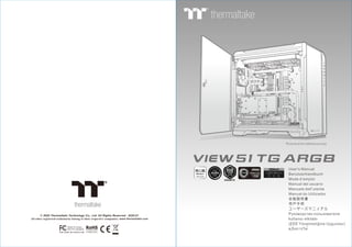
  • 1. User's Manual Benutzerhandbuch Mode d’emploi Manual del usuario Manuale dell’utente Manual do Utilizador 安裝說明書 用戶手冊 ユーザーズマニュアル Руководство пользователя kullanıcı elkitabı (EEE Yönetmeliğine Uygundur) คู่มือการใช้ © 2020 Thermaltake Technology Co., Ltd. All Rights Reserved. 2020.01 All other registered trademarks belong to their respective companies. www.thermaltake.com Tested To Comply With FCC Standards FOR HOME OR OFFICE USE Picture is for reference only view 51 TG ARGB
  • 2. Join Tt Community To Receive Benefits Tt LCS-Liquid Cooling Support Certification TT Premium Dear Valued Customer, Thank you for choosing Thermaltake. As a new user we value your thoughts and opinions and your feedback is important to us. We at Thermaltake would like to use this opportunity to invite you to join our Community Forums. Register today to start enjoying the full benefits of our community. Benefits of being a member: Quick and responsive user support Receive help and advice with new builds Keep up to date with new product releases Share your thoughts and builds with the community Enter monthly contests and giveaways Tt LCS Certified is a Thermaltake exclusive certification applied to only products that pass the design and hardcore enthusiasts standards that a true LCS chassis should be held to. The Tt LCS certification was created so that we at Thermaltake can designate to all power users which chassis have been tested to be best compatible with extreme liquid cooling configurations to ensure you get the best performance from the best features and fitment. Brand official website http://www.thermaltake.com/ Global Facebook https://www.facebook.com/ThermaltakeInc TT Premium To continue achieving the corporate mission of delivering the perfect user experience, Thermaltake developed “TT Premium” with the essence of combining supreme quality products with a new logo design. TT Premium is far more than just a guarantee of quality. Behind the name, it represents the passion in DIY, Modding and Thermaltake’s desire to be the most innovative brand in the PC hardware market. To satisfy the demand of the high-end PC users, TT Premium follows its core values of Excellent Quality, Unique Design, Diverse Combinations and Boundless Creativity to provide a high performance PC product for every enthusiast. http://ttpremium.com Taiwan Facebook http://www.facebook.com/ThermaltakeTW Global community forums http://community.thermaltake.com Chapter 1. Product Introduction Specification Accessory Warning and Notice 1.0 1.1 1.2 01 02 03 Contents Chapter 2. Installation Guide 2.0 2.1 2.2 2.3 2.4 2.5 2.6 2.7 2.8 2.9 Side Panels Disassembly Power Supply Unit (PSU) Installation Motherboard Installation 3.5" & 2.5" HDD Installation PCI Card Installation RGB Switch Mode Air Cooling Installation Liquid Cooling Installation Liquid Cooling Installation - 200mm Fan Pump Installation 05 06 07 08 10 12 13 14 15 16 Chapter 3. Leads Installation Case LED Connection USB 3.0 Connection Audio Connection 3.1 3.2 3.3 17 17 17 Chapter 4. Other 4.1 4.2 23 24 Thermaltake Power Supply Series (Optional) Tt RGB Plus Ecosystem *Picture for reference only *Information in the user manual is subject to change without notice
  • 3. Specification Accessory 8 Figure Parts Name Q'ty 2 4 24 1 8 10 1 Used for 2 Full Tower Radiator Support Case Type Dimension (H*W*D) 2.5” x 2 or 3.5” x 2 (With HDD Rack) ; 2.5” x 2 (With HDD Bracket) 550 x 315 x 525 mm (21.65 x 12.4 x 20.67 inch) Side Panel Tempered Glass x 3 (4mm thickness) Material SPCC Cooling System Front (intake) : 200 x 200 x 30 mm Addressable RGB fan (600rpm, 24dBA) x 2 Rear (exhaust) : 120 x 120 x 25 mm Addressable RGB fan (1000rpm, 27.2dBA) Drive Bays - Accessible - Hidden Expansion Slots 8 Motherboards 6.7” x 6.7” (Mini ITX), 9.6” x 9.6” (Micro ATX), 12” x 9.6” (ATX), 12” x 10.5” (CEB) I/O Port Type-C x 1, USB 3.0 x 2, USB 2.0 x 2, HD Audio x 1 PSU Standard PS2 PSU (optional) Fan Support Front: 3 x 120mm, 3 x 140mm, 2 x 200mm Top: 3 x 120mm, 3 x 140mm, 2 x 200mm Rear: 1 x 120mm Right: 3 x 120mm, 2 x 140mm Bottom: 3 x 120mm (Without Water Pump) Front: 1 x 360mm, 1 x 280mm Top: 1 x 360mm, 1 x 280mm Right: 1 x 360mm, 1 x 280mm Bottom: 1 x 360mm (Without Water Pump) Clearance CPU cooler height limitation: 175mm VGA length limitation: 300mm (With Water Pump) 440mm (Without Water Pump) PSU length limitation: 200mm MB, 3.5” HDD Power MB Stand-off Cable Management Motherboard Alarm 2030 Fan Backup Backup 2.5” HDD / SSD Backup Stand-off #6-32 x 6.5mm Screw #6-32 x 6mm Screw #6-32 x 6mm Screw M3 x 5mm Cable ties Buzzer Thumb Screw #6-32 x 5mm Rubber Screw #6-32 x 38mm Nut setter 16 Velcro cable tip 3 MB Signal bridge cable (ASUS / MSI) 1 MB Signal bridge cable (GIGABYTE) 1 Cable Management LED Signal Sync LED Signal Sync 1 2
  • 4. Warning and Notice <175 mm <300 mm Warning!! CPU Cooler Height Limitation: Please ensure that your CPU cooler does NOT exceed 175mm (6.89 inches) height. VGA (Add-on card) Length Limitation: Please ensure that your VGA (Add-on card) does NOT exceed 300mm (11.81 inches) length. Warnung!! CPU-Kühler Höhenbeschränkung: Bitte stellen Sie sicher, dass Ihr CPU-Kühler 175 mm (6,89 Zoll) Höhe nicht überschreitet. VGA (Add-on-Karte) Längenbeschränkung: Bitte stellen Sie sicher, dass Ihre VGA (Add-on-Karte) 300 mm (11,81 Zoll) Länge nicht überschreitet. Avertissement ! Limite de hauteur du ventilateur de CPU : Vérifiez que la hauteur du ventilateur de CPU ne dépasse pas 175 mm. Limite de longueur de la carte (complémentaire) VGA : Vérifiez que la longueur de votre carte (complémentaire) VGA ne dépasse pas 300 mm Precaución Limitación de altura del refrigerador de CPU: Asegúrese de que la altura de su refrigerador de CPU no excede los 175 mm (6,89 pulgadas). Limitación de longitud de la tarjeta de vídeo (adicional): Asegúrese de que la longitud de su tarjeta de vídeo (adicional) no excede los 300 mm (11,81 pulgadas). Attenzione! Limitazione altezza dissipatore CPU: Assicurarsi che l’altezza del dissipatore CPU NON superi 175 mm (6,89 pollici). Limitazione lunghezza VGA (scheda aggiuntiva): Assicurarsi che la lunghezza del VGA (scheda aggiuntiva) NON superi 300 mm (11,81 pollici). Atenção!! Limite de altura para o dissipador do CPU: O limite de altura para o dissipador do CPU é 175 mm (6,89 polegadas). CPU 冷卻器的高度限制: 請確保 CPU 冷卻器的高度不超過 175 mm (6.89 英吋)。 VGA (附加介面卡) 的長度限制: 請確保 VGA (附加介面卡) 的長度不超過 300 mm (11.81 英吋)。 CPU 散热器高度限制: 请确保 CPU 散热器的高度不超过 175 mm(6.89 英寸)。 VGA(附加卡)长度限制: 请确保 VGA(附加卡)的长度不超过 300 mm(11.81 英寸)。 CPUクーラーの高さ制限: CPUクーラーの高さが175mmを超えていないことを確認してください。 VGA(アドオンカード)の長さ制限: VGA(アドオンカード)の長さが300mmを超えていないことを確認してください。 Ограничение по высоте охладителя ЦП Убедитесь, что высота охладителя ЦП (центрального процессора) НЕ превышает 175 м (6,89 дюйма). Ограничение по длине видеокарты VGA (плата расширения) Убедитесь, что длина видеокарты VGA (плата расширения) НЕ превышает 300 мм (11,81 дюйма). CPU Soğutucu Yükseklik Sınırlaması: Lütfen CPU soğutucunuzun yüksekliğinin 175mm’yi (6,89 inç) GEÇMEDİĞİNDEN emin olun. VGA (Eklenti kartı) Uzunluk Sınırlaması: Lütfen VGA’nızın (Eklenti kartı) uzunluğunun 300mm’yi (11,81 inç) GEÇMEDİĞİNDEN emin olun. Limite de comprimento para VGA (placa gráfica): O limite de comprimento para VGA (placa gráfica) é 300 mm (11,81 polegadas). 警告!! 警告!! 警告 Внимание! Uyarı!! คำเตือน!! ขีดจำกัดความสูงสำหรับฮีตซิงก์ของ CPU: ขีดจำกัดความสูงสำหรับฮีตซิงก์ของ CPU คือ 175 มม. (6.89 นิ้ว) ขีดจำกัดความยาวสำหรับ VGA (การ์ดแสดงผล): ขีดจำกัดความยาวสำหรับ VGA (การ์ดแสดงผล) คือ 300 มม. (11.81 นิ้ว) 3 4
  • 5. Side Panels Disassembly English / Remove the screws on the back of the chassis, and open the side panel Deutsch / Entfernen Sie die Schrauben auf der Rückseite des Gehäuses und öffnen Sie das Seitenteil Français / Enlevez les vis à l’arrière du châssis et ouvrez le panneau latéral Español / Extraiga los tornillos de la parte posterior de la caja y abra el panel lateral Italiano / Rimuovere le viti sulla parte posteriore dello chassis e aprire il pannello laterale Português/ Remova os parafusos na parte de trás da caixa e abra o painel lateral 繁體中文 / 移除機殼後方螺絲,將側窗打開 日本語 / シャーシ背面のねじを取り外し、サイドパネ ルを開きます Русский / Открутите винты на задней стенке корпуса и откройте боковую панель 简体中文 / 卸除机壳后方螺丝,将侧窗打开 Türkçe / Kasanın arkasındaki vidaları çıkarın ve yan paneli açın ภาษาไทย / ถอดสกรูที่ด้านหลังของแชสซีส์ แล้วเปิดแผงด้านข้าง Power Supply Unit (PSU) Installation English / Deutsch / Français / Placez l’alimentation dans la position appropriée. Español / Instale la PSU en la ubicación correcta. Italiano / Place the PSU in proper location. Platzieren Sie das Netzteil in der richtigen Position. Posizionare la PSU in modo corretto. Português/ Coloque o PSU na sua devida posição. 繁體中文 / 简体中文 / 日本語 / Русский / Установите блок питания в надлежащее место. Türkçe / 將電源供應器放在正確的位置 将电源供应器放在正确的位置 PSUを適切なロケーションに取り付けます。 PSU’yu, uygun konuma yerleştirin. ภาษาไทย / วาง PSU ในตำแหน่งที่เหมาะสม 5 6
  • 6. Motherboard Installation English / 1.Lay down the chassis. 2.Install the motherboard in proper location and secure it with screws. Deutsch / 1.Legen Sie das Gehäuse auf die Seite. 2.Installieren Sie die Hauptplatine in ihrer vorgesehenen Position und sichern Sie sie mit Schrauben. Français / 1.Posez à plat le châssis. 2.Installez la carte mère dans l'endroit approprié et sécurisez-la avec des vis. Español / 1. Tumbe el chasis. 2. Instale la placa madre en la ubicación adecuada y asegúrela con tornillos. Italiano / 1.Poggiare lo chassis. 2.Installare la scheda madre nella posizione appropriata e fissarla con le viti. Português/ 1. Deixe a caixa. 2. Instale a motherboard no local adequado e aparafuse. 繁體中文 / 1. 將機殼平放。 2. 將主機板放置在合適的位置並用零件包中之螺 絲固定。 日本語 / 1.シャーシを下に置きます。 2.マザーボードを適切な場所に取り付け、ねじで 固定します。 Русский / 1. Раскройте системный блок. 2. Установите материнскую плату в надлежащее место и закрепите ее винтами. 简体中文 / 1. 放平机箱。 2. 在合适的位置安装主板并以螺丝安全固定。 Türkçe / 1.Kasayı yan yatırın. 2.Ana kartı uygun konuma takın ve vidalarla sabitleyin. ภาษาไทย / 1.วางแชสซีส์นอนลง 2.ติดตั้งเมนบอร์ดในตำแหน่งที่เหมาะสม แล้วขันสกรูยึดให้แน่น 3.5" & 2.5" HDD Installation TypeA 3.5” HDD SSD / 2.5” HDD 7 8
  • 7. English / 繁體中文 / 1. Pull the HDD tray out. 1. 將硬碟托盤取出 2. Place the 2.5” or 3.5” hard drive on the tray 2. 將2.5”或3.5”硬碟放置在硬碟托盤上,用螺絲固 and secure it with screws. 定硬碟 3. Slide the HDD tray back to the HDD cage. 3. 將硬碟托盤放回硬碟磁架中 Deutsch / 简体中文 / 1. Ziehen Sie den HD-Schacht heraus. 1. 将硬盘托盘取出 2. Montieren Sie die 2,5 oder 3,5 Zoll Festplatte 2. 将2.5”或3.5”硬盘放置在硬盘托盘上, im Schacht und sichern Sie sie mit Schrauben. 用螺丝固定硬盘 3. Schieben Sie den Schacht wieder in den 3. 将硬盘托盘放回硬盘磁架中 Festplattenkäfig. 日本語 / Français / 1.HDDトレイを引き出して外します。 1. Enlevez le boîtier du disque dur. 2.2.5インチHDD、SSD もしくは 3.5インチ 2. Placez le disque dur de 2,5” ou de 3,5” dans le HDDドライブをトレイにネジで固定します。 boîtier et fixez-le avec des vis. 3. HDDトレイをHDDケージに戻します。 3. Refaites glisser le boîtier du disque dur dans la cage de disques durs. Русский / 1. Вытяните лоток для жестких дисков. Español / 2. Установите 2,5- или 3,5-дюймовый жесткий 1. Extraiga la bandeja del disco duro. диск в лоток и закрепите его винтами. 2. Coloque el disco duro de 2’5 ó 3'5” en la 3. Установите лоток для жестких дисков bandeja y fíjelo con los tornillos. обратно в каркас. 3. Vuelva a meter la bandeja del disco duro en su hueco. Türkçe / 1. HDD tepsisini dışarı çekin. Italiano / 2. 2,5” veya 3,5” sabit disk sürücüsünü tepsinin 1. Estrarre il vano HDD. üzerine yerleştirin ve vidalarla sabitleyin. 2. Posizionare il disco fisso da 2,5” o 3,5” nel 3. HDD tepsisini HDD kafesine geri yerleştirin. vano e fissarlo con le viti. 3. Fare scorrere l’HDD indietro verso la struttura ภาษาไทย / a gabbia HDD. 1. ดึงถาด HDD ออกมา 2. วางฮาร์ดไดร์ฟขนาด 2.5” หรือ 3.5” Português / ลงบนถาดแล้วขันสกรูยึดให้แน่น 1. Puxe a bandeja do disco rígido para fora. 3. เลื่อนถาด HDD กลับเข้าในโครง HDD 2. Coloque o disco rígido de 2,5” ou 3,5” na bandeja e fixe com parafusos. 3. Deslize a bandeja do disco rígido de volta para a caixa do disco rígido. TypeB TypeC SSD / 2.5” HDD SSD / 2.5” HDD PCI Card Installation TypeA 9 10
  • 8. (Optional) Vertical GPU installation ※Riser Cable is not included TypeB RGB Switch Mode I/O Port How to connect MB Flow Mode Wave Mode RGB Lighting Radar Mode Breath Mode Single Color Full Lighted Mode Light Off Mode 2 Mode 1 Mode 3 (Single Color) Mode 4~10 (Red, Yellow, Green, Cyan, Blue, White, Purple) Mode 11~18 (RGB, Red, Yellow, Green, Cyan, Blue, White, Purple) Mode 20~26 (Red, Yellow, Green, Cyan, Blue, White, Purple) Mode 19 Mode 27 ※ Long press on RGB button for 3 seconds, fan will blink twice which now are controlled by MB software. And vice versa. Aura Addressable Strip Header(s) Addressable RGB LED Header(s) AORUS RGB Fusion with Digital LEDs ASUS GIGABYTE JRGB-strip Header(S) MSI MSI +5V D G JRAINBOW G ASROCK 11 12
  • 9. Air Cooling Installation Liquid Cooling Installation Front 120mm x 3 or 140mm x 3 or 200mm x 2 Bottom 120mm x 3 120mm x 3 or 140mm x 2 Top 360 x 30 mm or 280 x 55 mm Bottom 360 x 30 mm Front 360 x 30 mm or 280 x 55 mm Right 360 x 64 mm or 280 x 55 mm Top 120mm x 3 or 140mm x 3 or 200mm x 2 Right 120mm x 1 Back ※ The Radiators are recommended to mount inside the chassis. 13 14
  • 10. Liquid Cooling Installation - 200mm Fan Radiator 360mm + 200mm Fan Pump Installation or Rubber 15 16
  • 11. Leads Installation Leads Installation Guide A. Case LED Connection / On the front of the case, you can find some LEDs and switch leads. Please consult your user manual of your motherboard manufacturer, then connect these leads to the panel header on the motherboard. B. USB 3.0 connection / 1. Make sure your motherboard supports USB 3.0 connection. 2. Connect the USB 3.0 cable to the available USB 3.0 port on your computer. C. Audio Connection / Please refer to the following illustration of Audio connector and your motherboard user manual. Please select the motherboard which used AC’97 or HD Audio(Azalia),(be aware of that your audio supports AC’97 or HD Audio (Azalia)) or it will damage your device(s). Anschlüsse herstellen A. Gehäuse-LED-Verbindungen / Auf der Gehäusevorderseite finden Sie einige LEDs und Verbindungen. Bitte nehmen Sie die Gebrauchsanweisung Ihres Motherboard Herstellers zur Hilfe und schließen Sie diese Verbindungen an die Panel Header Belegung des Motherboards an. B. USB 3.0 Anschluss / 1. Stellen Sie sicher, dass Ihre Hauptplatine den USB 3.0 Anschluss unterstützt. 2. Verbinden Sie das USB 3.0 Kabel mit dem USB 3.0 Port auf Ihrem Computer. C. Audio Anschlüsse / Bitte beachten Sie die folgende Abbildung der Audio Anschlüsse und die Anweisung in der Gebrauchsanweisung Ihres Motherboards. Bitte wählen Sie das Motherboard, das AC’97 oder HD Audio(Azalia) verwendet, (achten Sie darauf, dass Ihr Audio AC’97 bzw. HD Audio (Azalia unterstützt)). Andernfalls entstehen schwere Schäden an Ihrem(n) Gerät(en)!!! USB 3.0 Connection USB 3.0 Connection PRESENCE# PRESENCE# BLACK BLACK SENSE1_RETURN SENSE1_RETURN AUD GND AUD GND SENSE2_RETURN SENSE2_RETURN YELLOW YELLOW BROWN BROWN RED RED PORT1 R PORT1 R PORT2 R PORT2 R PORT1 L PORT1 L BLUE BLUE PORT2 L PORT2 L SENSE_SEND SENSE_SEND KEY KEY PURPLE PURPLE GREEN GREEN ORANGE ORANGE BLACK BLACK AUDIO HD AUDIO Function AUDIO HD AUDIO Function English Deutsch Guide d'installation des fils A. Connexion des voyants du boîtier / Sur la face avant du boîtier, vous trouverez plusieurs voyants et les fils des boutons. S'il vous plaît consultez le guide d'utilisateur du fabricant de votre carte mère, puis connectez ces fils aux onnecteurs sur la carte mère. B. Connexion USB 3.0 / 1. Vérifiez que votre carte mère prend en charge la connexion USB 3.0. 2. Connectez le câble USB 3.0 au port USB 3.0 disponible sur votre ordinateur. C. Connexion Audio / S'il vous plaît référez vous à l'illustration suivante du connecteur audio et au guide de l'utilisateur de votre carte mère. S'il vous plaît sélectionnez une carte mère supportant AC'97 ou HD Audi (Azalia), (faites attention que votre audio supporte l'AC'97 ou HD Audio (Azalia)) sinon cela pourrait endommager votre matériel. Guía de Instalación de Cables A. Conexión del LED de la caja / En la parte frontal de la caja, encontrará algunos LED y cables de interruptores. Consulte el manual del usuario del fabricante de la placa madre, a continuación conecte estos cables al conector de la placa madre. B. Conexión USB 3.0 / 1. Asegúrese de que la placa base admite conexión USB 3.0. 2. Conecte el cable USB 3.0 al puerto USB 3.0 disponible en el equipo. C. Conexión de Audio / Consulte la siguiente ilustración del conector de Audio y el manual del usuario de la placa madre. Seleccione la placa madre que utiliza AC’97 o HD Audio (Azalia), (asegúrese de que su audio admite AC’97 o HD Audio (Azalia)) si no, sus dispositivos resultarán dañados Français Español A A B B C C 17 18
  • 12. Guida di installazione dei contatti A. Connessione del LED del case / Nella parte anteriore del case, sono presenti alcuni contatti per interruttori e LED. Consultare il manuale utente del produttore della scheda madre, quindi connettere i contatti alla parte superiore del pannello sulla scheda madre. B. Connessione USB 3.0 / 1. Accertarsi che la scheda madre supporti la connessione USB 3.0. 2. Collegare il cavo USB 3.0 alla porta USB 3.0 disponibile sul computer. C. Connessione Audio / Fare riferimento all’illustrazione riportata di seguito del connettore Audio e al manuale utente per la scheda madre.Selezionare la scheda madre relativa a AC’97 o HD Audio (Azalia) e considerare che il supporto audio è compatibile con AC’97 o HD Audio (Azalia); in caso contrario, le periferiche potrebbero venire danneggiate. Guia de Instalação Eléctrica A. Ligação do LED da Caixa / Na parte dianteira da caixa pode encontrar alguns LEDs e fios eléctricos. Consulte o manual de utilizador do fabricante da sua motherboard e ligue os fios à parte superior do painel na motherboard. B. Ligação USB 3.0 / 1. Certifique-se que a sua motherboard suporta ligação USB 3.0. 2. Ligue o cabo USB 3.0 à porta USB 3.0 disponível no seu computador. C. Ligação Áudio / Consulte a imagem seguinte do conector Áudio e o manual de utilizador da sua motherboard. Seleccione a motherboard que utiliza AC’97 ou HD Áudio(Azalia), (verifique se a sua placa de áudio suporta AC’97 ou HD Áudio(Azalia)) ou irá danificar o(s) seu(s) dispositivo(s). Italiano Português 線材安裝說明 A. 機殼LED連接方式 / 在機殼前方的面板後面,可以找到一些LED與開關線材(POWER Switch….),請參考主機板使用說明 書,並將機殼上的線材正確地連接到主機板上,這些線材通常都會印有標籤在上面,如果沒有的話,請找出機殼前方面板上線 材原本的位置以知道正確的來源。 B. USB 3.0 連接 / 1. 請確認主機板是否支援USB 3.0傳輸介面。 2. 連接USB 3.0傳輸線至主機板上的USB3.0接埠。 C. 音效連接 / 請根據下面的音源接頭圖示與主機板使用手冊來連接音效裝置,請確認主機板上的音效裝置是支援AC' 97音效或 是HD音效(Azalia),裝置錯誤可能會導致主機板音效裝置的毀損,某些主機板的音效裝置不會與下方的圖示完全相同,請參酌 主機板使用手冊以得到正確的安裝資訊 线材安装说明 A. 机壳LED连接方式 / 在机壳前方的面板后面,可以找到一些LED与开关线材(POWER Switch….),请参考主板使用说明 书,并将机壳上的线材正确地连接到主板上,这些线材通常都会印有标签在上面,如果没有的话,请找出机壳前方面板上线 材原本的位置以知道正确的来源。 B. USB 3.0 连接 / 1.请确认主板是否支持USB 3.0传输接口。 2.连接USB 3.0传输线至主板上的USB3.0接埠。 音效连接 / 请根据下面的音源接头图示与主板使用手册来连接音效装置,请确认主板上的音效装置是支持AC' 97音效或是 C. HD音效(Azalia),装置错误可能会导致主板音效装置的毁损,某些主板的音效装置不会与下方的图标完全相同,请参酌主 板使用手册以得到正确的安装信息 繁體中文 简体中文 USB 3.0 Connection USB 3.0 Connection PRESENCE# PRESENCE# BLACK BLACK SENSE1_RETURN SENSE1_RETURN AUD GND AUD GND SENSE2_RETURN SENSE2_RETURN YELLOW YELLOW BROWN BROWN RED RED PORT1 R PORT1 R PORT2 R PORT2 R PORT1 L PORT1 L BLUE BLUE PORT2 L PORT2 L SENSE_SEND SENSE_SEND KEY KEY PURPLE PURPLE GREEN GREEN ORANGE ORANGE BLACK BLACK AUDIO HD AUDIO Function AUDIO HD AUDIO Function A A B B C C 20 19
  • 13. Указания по прокладке кабелей A. Подключение индикаторов корпуса / В передней части корпуса расположены индикаторы и провода выключател ей. Перед подсоединением этих проводов к монтажной колодке панели на материнской плате изучите руководство пользователя производителя материнской платы. B. Подключение USB 3.0 / 1. Убедитесь, что материнская плата поддерживает подключение по стандарту USB 3.0. 2. Подсоедините кабель USB 3.0 к свободному порту USB 3.0 компьютера. C. Подключение аудиоразъема / См. следующую иллюстрацию аудиоразъема и руководство пользователя материн ской платы. Выберите материнскую плату, в которой используется кодек AC'97 или HD Audio (Azalia) (убедитесь, что звуковая плата поддерживает кодек AC'97 или HD Audio (Azalia)). В противном случае можно повредить устройства. リード線の取り付けガイド A. ケース LED の接続 / ケース前面には、LEDとスイッチリード線があります。 マザーボードメーカーのユーザーマニュ アルを参照し、これらのリード線をマザーボードのパネルヘッダに接続してください。 B. USB 3.0 の接続 / 1. お使いのマザーボードがUSB 3.0接続をサポートしていることを確認してください。 2. USB 3.0ケーブルをコンピュータの空いているUSB 3.0ポートに接続します。 C. オーディオ接続 / オーディオコネクタの次の図とマザーボードのユーザーマニュアルを参照してください。AC’97または HDオーディオ(Azalia)を使用するマザーボードを選択してください(オーディオがAC’97またはHDオーディオ(Azalia)をサポ ートしていることを確認してください)。サポートしていないと、デバイスが損傷します)。 日本語 Русский Ara Kablo Kurulum Kılavuzu A. Kasa ışık bağlantısı / Kasanın ön kısmında bazı ışıklar ve anahtar ara kabloları görebilirsiniz. Lütfen anakart üreticinizin sağladığı kullanım kılavuzuna bakın ve daha sonra, bu ara kabloları, anakart üzerindeki panel bağlantı noktalarına bağlayın. B. USB 3.0 Bağlantısı / 1. Ana kartınızın USB 3.0 bağlantısını desteklediğinden emin olun. 2. USB 3.0 kablosunu, bilgisayarınızdaki kullanılabilir USB 3.0 bağlantı noktasına bağlayın. C. Ses Bağlantısı / Lütfen aşağıdaki Ses konektörü resmine ve anakartınızın kullanım kılavuzuna bakın. Lütfen AC’97 veya HD Audio(Azalia) spesifikasyonunu kullanan bir anakart seçin (ses sisteminizin AC’97 veya HD Audio (Azalia) spesifikasyonunu desteklediğini unutmayın); aksi takdirde, aygıt(lar)ınız zarar görür. คู่มือการติดตั้งสายไฟ A. การเชื่อมต่อไฟ LED ของเคส / ที่ด้านหน้าของเคส คุณจะเห็นไฟ LED และสายไฟของสวิตซ์ กรุณาศึกษารายละเอียดจากคู่มือผู้ใช้ของผู้ผลิตแผงวงจรหลักของคุณ จากนั้นให้เชื่อมต่อสายไฟเหล่านี้เข้ากับส่วนหัวของแผงบนแผงวงจรหลัก B. การเชื่อมต่อ USB 3.0 / 1. ตรวจดูให้แน่ใจว่าแผงวงจรหลักของคุณรองรับการเชื่อมต่อ USB 3.0 2. เชื่อมต่อสาย USB 3.0 เข้ากับพอร์ต USB 3.0 ที่สามารถใช้งานได้บนคอมพิวเตอร์ของคุณ C. การเชื่อมต่ออุปกรณ์รับส่งสัญญาณเสียง/ กรุณาดูรายละเอียดจากภาพประกอบของตัวเชื่อมต่อสัญญาณเสียงต่อไปนี้ และคู่มือผู้ใช้ของผู้ผลิตแผงวงจรหลักของคุณ กรุณาเลือกแผงวงจรหลักที่ใช้ AC’97 หรือ HD Audio(Azalia) (กรุณาตรวจสอบให้แน่ใจว่าอุปกรณ์รับส่งสัญญาณเสียงของคุณรองรับ AC’97 หรือ HD Audio (Azalia)) มิฉะนั้นอุปกรณ์ของคุณอาจเสียหายได้ Türkçe ภาษาไทย USB 3.0 Connection USB 3.0 Connection PRESENCE# PRESENCE# BLACK BLACK SENSE1_RETURN SENSE1_RETURN AUD GND AUD GND SENSE2_RETURN SENSE2_RETURN YELLOW YELLOW BROWN BROWN RED RED PORT1 R PORT1 R PORT2 R PORT2 R PORT1 L PORT1 L BLUE BLUE PORT2 L PORT2 L SENSE_SEND SENSE_SEND KEY KEY PURPLE PURPLE GREEN GREEN ORANGE ORANGE BLACK BLACK AUDIO HD AUDIO Function AUDIO HD AUDIO Function A A B B C C 22 21
  • 14. 24 23