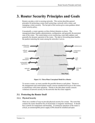
This document provides a router security configuration guide that aims to help network administrators and security officers improve the security of their networks by configuring routers to control access, resist attacks, shield other network components, and protect network traffic integrity and confidentiality, with a focus on implementing these security measures on Cisco routers running Cisco IOS software. The guide covers background topics, security principles and goals, configuration examples, advanced security services, testing approaches, and additional issues.


![Background and Review
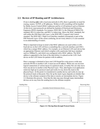
2.3.3. Classful IP Addressing
Under the original IP standards, there are four “classes” of IP addresses, referred to
as Classes A, B, C, and D. In addition there a number of special addresses. Special
addresses are used for such things as to broadcast to all hosts on a network or to
specify a loopback packet which will never leave the host. The class determines how
much of the 32 bit address is used to specify the network address and how much is
used to specify the host within that network. The class is determined by the first one
to four bits of the address. Any address beginning with a zero bit is a Class A
address. Any address beginning with bits 10 is a Class B address. Any address
beginning with bits 110 is Class C, and any beginning with bits 1110 is class D.
For any class, it is also possible to take the host portion of the address and further
divide that range into two fields, which specify a subnet address and a host address
respectively. This is done by specifying a parameter called a subnet mask. For a
fuller discussion of subnetting see Albritton’s book [1] or one of the other references
listed in Section 2.7.1.
There are also a set of IP addresses that are reserved for experimental or private
networks; these addresses should not be used on the Internet or other wide-area
networks (see Section 4.3).
In addition to both source and destination addresses, there is a good bit of
information in an IP header. It should be noted that the first 4 bits of an IP header
contain a version number so new versions of the protocol can be implemented.
Moreover the second 4 bits specify the length of the header. Thus it is quite feasible
to introduce longer IP addresses. For a detailed explanation of TCP/IP packet header
formats, see Stevens’ book [10].
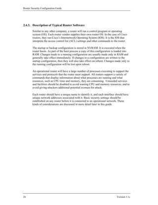
2.3.4. Classless Inter-Domain Routing (CIDR) and IP Addressing
As the Internet grew over the 1980s and early 1990s, it encountered two problems
related to the expanding number of networks and hosts. One was address depletion,
most notably the exhaustion of Class B networks, and the other was increased route
table sizes. While many networks have more hosts than a single Class C address can
accommodate (255 hosts), very few have enough to “fill” a Class B address range
(65,535 hosts). Allocating an entire Class B network to an organization that only
needed 1000 addresses would be (and was) terribly wasteful. CIDR avoids this
problem by eliminating the notion of a ‘class’, and allocating a block of addresses
using a netmask of the smallest size that satisfies the needs of the recipient. The
netmask simply specifies the number of bits in the assigned address that designate the
network portion, the remaining bits are the host (or subnet) portion.
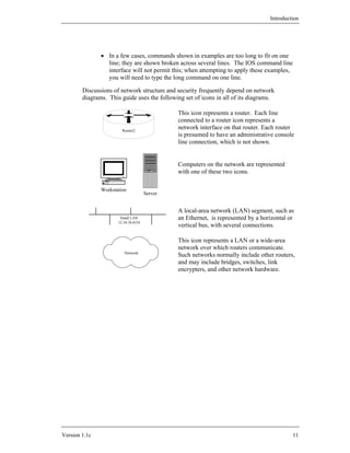
For example, under CIDR, an organization that needed 1000 addresses would be
assigned a netmask of 22 bits. (Another way to think of this is that CIDR allocates
several contiguous Class C addresses to a network. The number of contiguous Class
C addresses allocated is a function of the size of the network.)
Version 1.1c 21](https://image.slidesharecdn.com/c4-040r-02-130310054952-phpapp01/85/C4-040-r-02-21-320.jpg)
![Router Security Configuration Guide
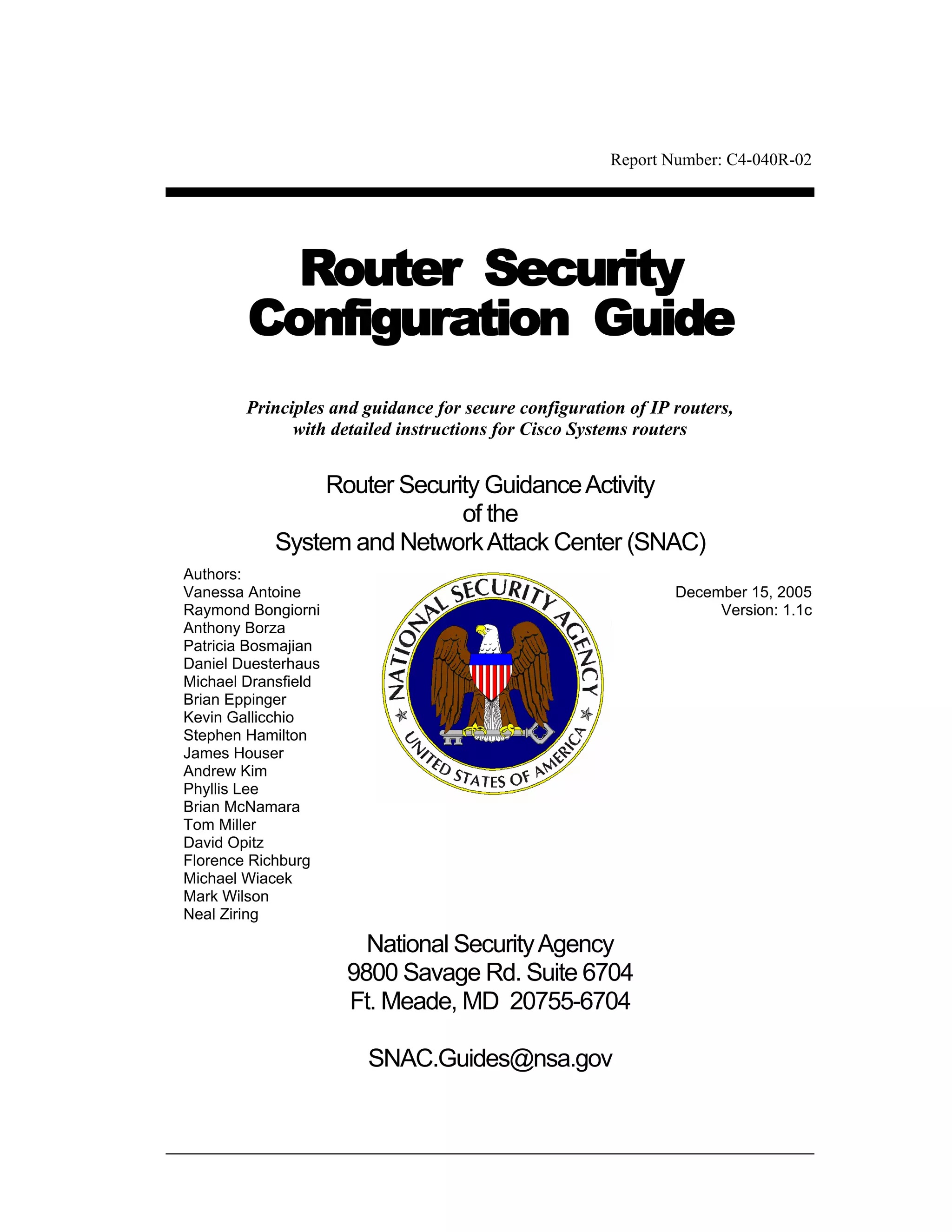
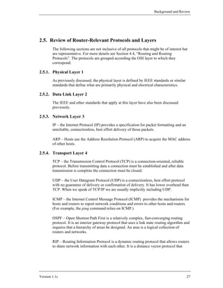
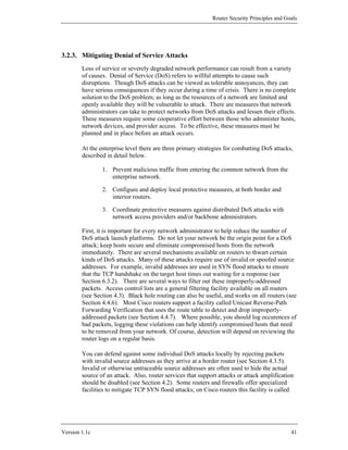
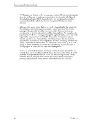
CIDR also permits address allocation authorities to allocate blocks of addresses
smaller than a Class C network. For example, if an organization required only 10
addresses, then they might be assigned a netmask of 28 bits.
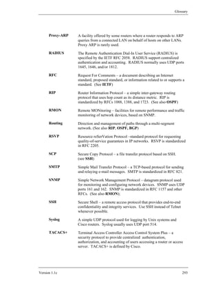
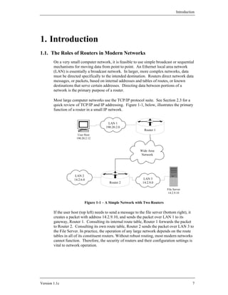
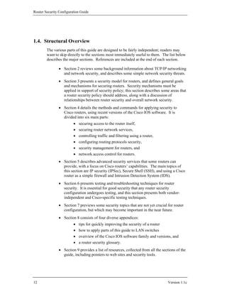
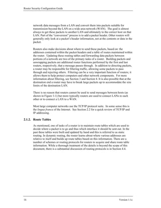
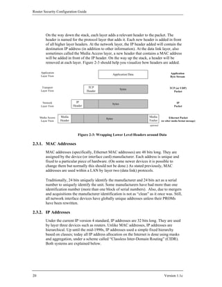
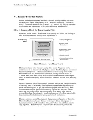
Another important aspect of CIDR is that it is hierarchical. A major allocation
authority might obtain a block of addresses with a netmask of 8 bits (16777216
addresses). They might allocate part of that large space as a block with netmask of
13 bits (524288 addresses) to a large ISP. The ISP might give big customer X a
block with netmask of 18 bits, and smaller customer Y a block with netmask of 28
bits. The addresses of customers X and Y would still be within the large block
‘owned’ by the major allocation authority. This is illustrated below.
Regional Authority
16777216 addresses 14.0.0.0/8
(14.0.0.0 - 14.255.255.255)
Major ISP
524288 addresses 14.0.0.0/13
(14.0.0.0 - 14.7.255.255)
Customer X Customer Y
16384 addresses 16 addresses 14.3.24.16/28
14.2.0.0/18
(14.2.0.0 - 14.2.63.255) (14.3.24.16-14.3.24.31)
Figure 2-4: Hierarchical IP Address Range Assignment under CIDR
Internet Routing and Aggregation
As alluded to in Section 2.1.2, any meaningful discussion of routing protocols in
general and BGP routing in particular is beyond the scope of this Background and
Review section. For these topics, there is a detailed treatment in Huitema’s book
[12], or consult RFCs 1771 and 1772. Section 4.4 of this guide covers security issues
for routing protocols. In general, the definitions of standard routing protocols specify
many of the details of: how routers keep track of available routes (route tables), how
routers exchange this information, and how they decide where to forward any given
packet. The prefixes which specify networks under CIDR vary in length, adding a bit
more complexity to routing. The network aggregation required by CIDR required the
development of a revised routing protocol for the Internet: BGP version 4 (BGP-4).
Aggregation
To avoid explosive growth in the size of routing tables as the Internet grows it is
desirable to somehow group or aggregate related network addresses together so that
they form only one routing table entry. This essentially forms “supernets”, which are
composed of several related networks which are collectively advertised as only one
aggregated path to that supernet. This reduces the number of entries required in the
22 Version 1.1c](https://image.slidesharecdn.com/c4-040r-02-130310054952-phpapp01/85/C4-040-r-02-22-320.jpg)
![Background and Review
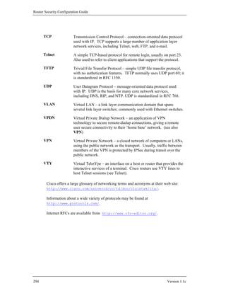
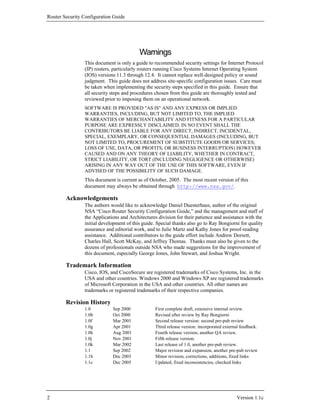
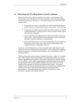
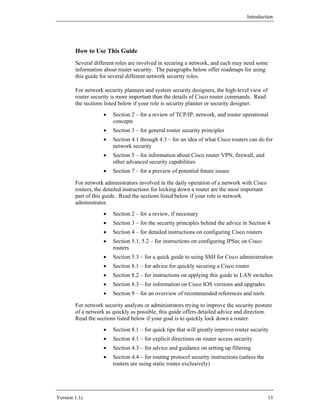
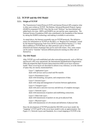
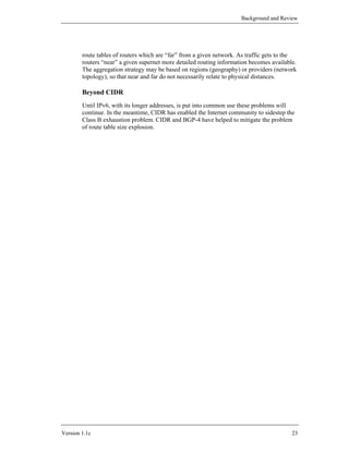
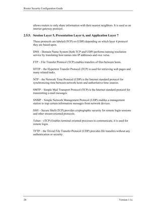
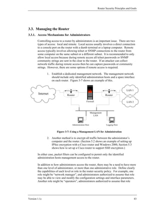
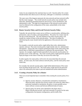
memory stores the IOS (or other router OS), and if there is enough flash it may store
more than one version of IOS. Figure 2-5 shows a simple representation of a notional
router’s hardware structure.
Network 0 Network 1
... Network n
Interface 0 Interface 1 Interface n
...
Routing Fabric
CPU
Configuration
Router
Console
Figure 2-5: A Notional Router’s Hardware Structure
Interfaces provide the physical connections from a router to networks. Interface types
include Ethernet, fast Ethernet, gigibit-Ethernet, token ring, FDDI, low-speed serial,
fast serial, HSSI, ISDN BRI, etc. Each interface is named and numbered. Interface
cards fit into slots in a router, and an external cable of the appropriate type is
connected to the card.
The CPU, also called the central processor or route processor, provides high-level
services for management, logging, routing, and control. It loads the configuration of
the router during boot-up, and manages the operation of the interfaces. When traffic
is being forwarded from one network to another, it usually does not touch the CPU;
instead, the packets travel across the routing fabric from the incoming interface to the
appropriate destination interface. Only management and control traffic for the router
travel to or from the CPU. This can be important, because the bandwidth of the
channel to the CPU may be far smaller than the bandwidth of the interfaces.
In addition to a number of interfaces, almost all routers have a console port providing
an asynchronous serial connection (RS-232). Also, most routers have an auxiliary
port, which is frequently used for connecting a modem for router management. [Do
not confuse the hardware serial ports with the concept of network protocol port
numbers (e.g. port 23 for Telnet).]
Version 1.1c 25](https://image.slidesharecdn.com/c4-040r-02-130310054952-phpapp01/85/C4-040-r-02-25-320.jpg)
![Router Security Configuration Guide
2.7. References
2.7.1. Books
[1] Albritton, J. Cisco IOS Essentials, McGraw-Hill, 1999.
An excellent introduction to basic IOS operations, with explanations of many
of the concepts. If you need more introductory information than this section
provides, this book is a good source.
[2] Ballew, S.M., Managing IP Networks with Cisco Routers, O’Reilly Associates,
1997.
A practical introduction to the concepts and practices for using Cisco routers.
[3] Chappell, L. Introduction to Cisco Router Configuration, Cisco Press, 1998.
A good book for learning the basics, with an emphasis on Cisco IOS.
[4] Chappell, L. (ed.) Advanced Cisco Router Configuration, Cisco Press, 1999.
For the network administrator who already has basic familiarity with Cisco
IOS, this book provides detailed information about a wide variety of topics
and features.
[5] Perlman, R., Interconnections: Bridges and Routers, McGraw-Hill, 1992.
This book offers good explanations of all the underlying concepts, with no
vendor emphasis.
[6] Sacket, G., Cisco Router Handbook, McGraw-Hill, 1999.
This thick book provides a lot of detail on the architecture of Cisco routers
and their operational concepts.
[7] Held, G. and Hundley, K., Cisco Security Architectures, McGraw-Hill, 1999.
For administrators already comfortable with basic operation of a router, this
book provides concepts and practical advice for using a router securely.
[8] Tannenbaum, A., Computer Networks, 2nd edition, Prentice-Hall, 1998.
A “classic”, well written, good background reading, an excellent source for
understanding all the concepts behind networks, routers, and TCP/IP.
[9] Stevens, W.R., Unix Network Programming, Prentice-Hall, 1998.
This book is primarily oriented toward network application programmers, but
it also provides a great deal of technical background information.
30 Version 1.1c](https://image.slidesharecdn.com/c4-040r-02-130310054952-phpapp01/85/C4-040-r-02-30-320.jpg)
![Background and Review
[10] Stevens, W.R., TCP/IP Illustrated – Volume 1, The Protocols, Prentice-Hall,
1994.
For really deep, technical, bit-by-bit analysis of the TCP/IP protocols, this
book is the best source.
[11] Cisco IOS 12.0 Configuration Fundamentals, Cisco Press, 1999.
This book provides a valuable reference for all the basic operation and
configuration features, with a great deal of background information, too.
[12] Huitema, C., Routing in the Internet, 2nd Edition, Addison-Wesley, 1999.
A deep and detailed textbook about IP routing technologies, protocols, and
how routing works in the Internet.
2.7.2. Papers
[13] “Internetworking Technology Overview”, Cisco Systems, 1999.
Available at:
http://www.cisco.com/univercd/cc/td/doc/cisintwk/ito_doc/
A series of introductory-level papers by Cisco, includes coverage of all the
topics discussed in this section.
[14] “OSI: The Network Layer”, Cisco Systems Brochure, Cisco Systems, 1997.
Available at: http://www.cisco.com/warp/public/535/2.html
[15] “TCP/IP”, Cisco Product Overview, Cisco Systems, 1997.
Available at: http://www.cisco.com/warp/public/535/4.html
2.7.3. RFCs
RFC stands for Request for Comments. As the official documents of the Internet
Engineering Task Force, these are the definitive sources for information about the
protocols and architecture of the Internet. All RFCs may be downloaded from
http://www.ietf.org/rfc.html .
[16] Postel, J., “User Datagram Protocol (UDP)”, RFC 768, 1980.
[17] Postel, J., “Internet Protocol (IP)”, RFC 791, 1981.
[18] Postel, J., “Transmission Control Protocol (TCP)”, RFC 793, 1981.
[19] Baker, F. (ed.), “Requirements for IP Version 4 Routers”, RFC 1812, 1996.
[20] Socolofsky, T. and Kale, C., “A TCP/IP Tutorial”, RFC 1180, 1991.
[21] Malkin, G. and Parker T.L., “Internet User’s Glossary”, RFC 1392, 1993.
Version 1.1c 31](https://image.slidesharecdn.com/c4-040r-02-130310054952-phpapp01/85/C4-040-r-02-31-320.jpg)
![Router Security Configuration Guide
[22] Rekhter, Y. and Li, T., “An Architecture of IP Address Allocation with CIDR”,
RFC 1518, 1993.
[23] Fuller, V., Li, T., Varadhan K., and Yu, J., “Classless Inter-Domain Routing
(CIDR): an Address Assignment and Aggregation Strategy”, RFC 1519, 1993.
32 Version 1.1c](https://image.slidesharecdn.com/c4-040r-02-130310054952-phpapp01/85/C4-040-r-02-32-320.jpg)
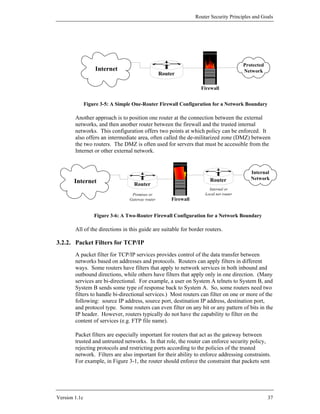
![Router Security Principles and Goals
3.5. References
3.5.1. Books and Manuals
[1] Chapman, D.B., Cooper, S., and Zwicky, E.D., Building Internet Firewalls, 2nd
Edition, O’Reilly & Associates, 2000.
A seminal overview of network boundary security concerns and techniques.
This revised edition includes all the sound background of the original, with
extensive updates for newer technologies.
[2] Held, G. and Hundley, K., Cisco Security Architectures, McGraw-Hill, 1999.
This book includes excellent general advice about router and router-related
network security, in addition to its Cisco-specific material.
[3] Stevens, W.R., TCP/IP Illustrated, Volume 1, Addison-Wesley, 1994.
The most comprehensive and readable guide to the TCP/IP protocol suite;
great technical background for any network analyst.
[4] Akin, T., Hardening Cisco Routers, O’Reilly & Associates, 2002.
A pragmatic and detailed guide to securing Cisco routers; includes a good
section on physical security.
3.5.2. Web Sites and On-Line Resources
[5] Cisco Internetworking Technology Overview
http://www.cisco.com/univercd/cc/td/doc/cisintwk/ito_doc/
This site contains a set of excellent technical overviews for a wide variety of
networking technologies. It is also included on every Cisco documentation
CD. The overview “Routing Basics” is a fine introduction to IP routing.
[6] IANA Port and Protocol Number Assignments
http://www.iana.org/assignments/port-numbers
http://www.iana.org/assignments/protocol-numbers
IANA houses the many unique parameters and protocol values necessary for
the operation of the Internet and its future development. Types of numbers
range from unique port assignments to the registration of character sets. In
the past, these numbers were documented through the RFC document series,
the last of these documents was RFC 1700, which is also now outdated.
Since that time, the assignments have been listed in this directory as living
documents, constantly updated and revised when new information is
available and new assignments are made. The port numbers are divided into
three ranges: the Well Known Ports, the Registered Ports, and the Dynamic
and/or Private Ports. The ‘port-numbers’ file contains the listing of all
registered port numbers.
Version 1.1c 51](https://image.slidesharecdn.com/c4-040r-02-130310054952-phpapp01/85/C4-040-r-02-51-320.jpg)
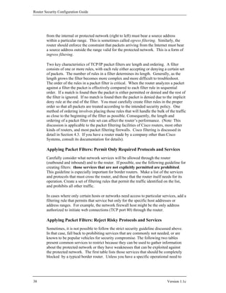
![Router Security Configuration Guide
[7] The RFC Editor Site
http://www.rfc-editor.org/
This is the main site for looking up Internet RFCs. The retrieval service
supports a variety of keyword searches, as well as straight by-number
lookup.
[8] “Network Security Policy: Best Practices White Paper”, Cisco White Paper,
Cisco Systems, 2000.
http://www.cisco.com/warp/public/126/secpol.html
A complex and highly detailed architecture and practices document for
setting up enterprise networks.
[9] Naidu, K. “Cisco Checklist”, Security Consensus Operational Readiness
Evaluation, SANS, 2000.
A detailed checklist of security and operational conditions to check for in the
audit of a router; available under: http://www.sans.org/SCORE/.
[10] “Cisco SAFE: A Security Blueprint for Enterprise Networks”, Cisco White
Paper, Cisco Systems, 2000.
This detailed white paper describes a threat model for enterprise networks,
and presents a network architecture designed to protect against it. This white
paper, and related ones, are available under the SAFE web page:
http://www.cisco.com/warp/public/cc/so/cuso/epso/sqfr/.
[11] Fraser, B. (ed.) “Site Security Handbook”, RFC 2196, September 1997.
This RFC provides extensive information about network and system security
policies, especially for systems connected to the Internet.
52 Version 1.1c](https://image.slidesharecdn.com/c4-040r-02-130310054952-phpapp01/85/C4-040-r-02-52-320.jpg)

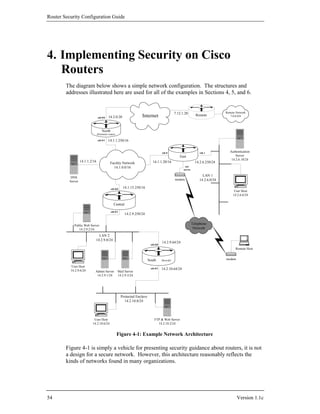
![Advanced Security Services
4.1. Router Access Security
This section discusses the various mechanisms used to protect the router itself. These
include physical access, user account protection, software protection, remote
administration concerns, and configuration issues. When thinking about the security
of your network it is important to consider these issues for all your systems, where
applicable, as well as for your routers.
4.1.1. Physical Security
Once an individual has physical access to a piece of networking equipment there is
no way to stop him from modifying the system. This problem is not only confined to
network devices but is also true of computers and any other electrical or mechanical
device. It is always a matter of time and effort. There are things that can be done to
make this more difficult, but a knowledgeable attacker with access can never be
completely defeated, only slowed down. One of the best additions to the security
features of a computer network is to limit access. Network infrastructure
components, like routers, are especially important because they are often used to
protect segments of the network and can also be used for launching attacks against
other network segments.
Network equipment, especially routers and switches, should be located in a limited
access area. If possible, this area should only be accessible by personnel with
administrative responsibilities for the router. This area should be under some sort of
supervision 24 hours a day and 7 days a week. This can be accomplished through the
use of guards, system personnel, or electronic monitoring. In practice, physical
security mechanisms and policies must not make access too difficult for authorized
personnel, or they may find ways to circumvent the physical security precautions.
If remote administration is used to configure and control routers, then consider ways
of protecting the machines used for remote administration, and the networks they use
to communicate with the router. Use access lists to limit remote administration
access to hosts that enjoy reasonable physical security. If possible, use encryption to
protect the confidentiality and integrity of the remote administration connection (see
Sections 5.2 and 5.3).
To illustrate one reason why physical security is critical to overall router security,
consider the password recovery procedure for Cisco routers. Using this procedure,
an individual with physical access can gain full privileged (enable) access to a Cisco
router without using a password. The details of the procedure varies between router
models, but always includes the following basic steps. An administrator (or an
attacker) can simply connect a terminal or computer to the console port and follow
the procedure below (taken from “Password Recovery Process” in [1]).
“Step 1 Configure the router to boot up without reading the
configuration memory (NVRAM). This is sometimes called
the test system mode.
Version 1.1c 55](https://image.slidesharecdn.com/c4-040r-02-130310054952-phpapp01/85/C4-040-r-02-55-320.jpg)
![Router Security Configuration Guide
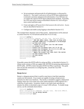
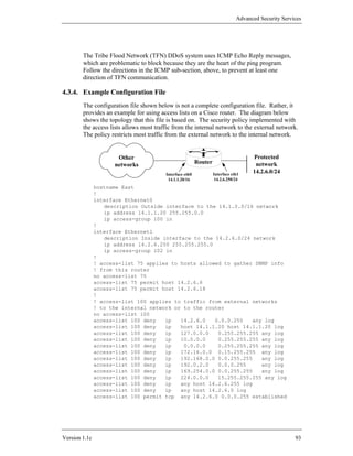
4.1.4. Router Network Traffic and the Loopback Interface
The pimary job of a router is forwarding traffic between networks, but routers also
generate some network traffic. Routers and other network devices communicate
using various management protocols, such as routing protocols, SNMP, NTP, and
TFTP. When the router initiates a network connection, that connection must have
some source address; typically a router will select a source address from one of the
addresses bound to one of its network interfaces. This can be problematic in several
ways, mainly because the source address for some services can vary.
In addition to physical interfaces, Cisco IOS routers have the ability to define internal
virtual interfaces, called loopback interfaces. It is considered best practice, in
configuring Cisco routers, to define one loopback interface, and designate it as the
source interface for most traffic generated by the router itself. Adopting this practice
yields several benefits for the overall stability and security management of a network,
because the address of the loopback interface is fixed. When a router is configured to
use the loopback interface for services, it is possible to configure the security of other
devices in the network more tightly. (When a service is configured to use the
loopback interface as its source, we say that the service is bound to that interface. It
means that IP packets generated by the router will have the loopback interface’s
address as their source address. Also, the loopback interface’s address does not
appear in any route-based network maps; hiding administrative aspects of your
network from potential attackers is usually good practice. For further discussion of
loopback interfaces, consult [5].)
To create a loopback interface, simply assign it an IP address. For a border router,
the loopback’s address usually should be in the range of the internal or DMZ
network, not the external network. Note that the loopback address cannot be the
same as the address of any other interface, nor can it be part of the same network as
any other interface.
Central# config t
Enter configuration commands, one per line. End with CNTL/Z.
Central(config)# interface loopback0
Central(config-if)# description Main loopback interface
Central(config-if)# ip address 14.2.11.250 255.255.255.255
Central(config-if)# end
Central#
In general, router network services that can be bound to the loopback interface should
be. Commands to set source interface bindings are given with the discussion of each
service in the rest of the guide.
4.1.5. Logins, Privileges, Passwords, and Accounts
Logins and Banners
A login banner, which includes a legal notice, should be set up on each operational
router. A legal notice usually includes a ‘no trespassing’ warning, a statement that all
use of the device must be authorized by the owning organization, a statement about
58 Version 1.1c](https://image.slidesharecdn.com/c4-040r-02-130310054952-phpapp01/85/C4-040-r-02-58-320.jpg)
![Advanced Security Services
the device being subject to monitoring, and perhaps a statement threatening
prosecution. A proper legal notice protects the ability of the owning organization to
pursue legal remedies against an attacker. Consult your organization’s legal staff or
general counsel for suitable language to use in your legal notice. See also [7] for
more discussion of banners and their content.
Do not include any network architecture or device information in the banner
message. Router model and location information should never be included. Be
careful not to provide any information in the banner message that should not be
shared with the general public. To set the router's message-of-the-day banner use the
command banner motd delimiter message delimiter. The delimiter can
be any single character.
The console (con) port is the default location for performing router management and
configuration. It is okay to leave a connection to the console port attached all the
time, but that terminal (or computer) should be standalone, and protected from
unauthorized access. The connection to the console port should not be left logged in.
Configure the console line to time out EXEC sessions, so that if an administrator
forgets to log out, the router will log him or her out automatically. The example
below shows how to set up the console line to enforce a five-minute timeout; the
command transport input none prevents remote access to the console port via
reverse-telnet (on IOS 12.0 and earlier only).
Central# config t
Enter configuration commands, one per line. End with CNTL/Z.
Central(config)# line con 0
Central(config-line)# transport input none
Central(config-line)# exec-timeout 5 0
Central(config-line)# exit
Central(config)#
Each authorized user should log in using their own account (for more details, see the
Accounts sub-section below). Apply the command login local to the console line
to enforce user log. Note that you must create at least one user account, otherwise
you will be locked out of the console. If you do not already have users accounts set
up, then create at least one before setting the console to use local login. The syntax
for creating a local user is username name privilege level password string.
The example below shows how to create an account with a password and set console
login.
Central(config)# username brian privilege 1 password g00d+pa55w0rd
Central(config)# line con 0
Central(config-line)# login local
Central(config-line)# end
Central#
The auxiliary port, if at all possible, should be disabled. Router Central, in the
sample network diagram (Figure 4-1), has no need for the aux port. The example
below shows how to disable login on the auxiliary port (login to enable mode first):
Central# config t
Enter configuration commands, one per line. End with CNTL/Z.
Version 1.1c 59](https://image.slidesharecdn.com/c4-040r-02-130310054952-phpapp01/85/C4-040-r-02-59-320.jpg)
![Router Security Configuration Guide
Central(config)# line aux 0
Central(config-line)# transport input none
Central(config-line)# login local
Central(config-line)# exec-timeout 0 1
Central(config-line)# no exec
Central(config-line)# exit
Section 4.1.5 discusses configuration of the auxiliary port if it is required for a
modem. If the auxiliary port is required for a second local serial connection then
configure it as shown below.
Central(config)# line aux 0
Central(config-line)# exec-timeout 5 0
Central(config-line)# login local
Central(config-line)# transport input none
Central(config-line)# exec
Central(config-line)# end
Central#
VTYs and Remote Administration
One primary mechanism for remote administration of Cisco routers is logging in via
Telnet or SSH; these connections are called virtual terminal lines. Login on the
virtual terminal lines should be disabled if remote administration is not absolutely
necessary. Remote administration without encryption is inherently dangerous
because anyone with a network sniffer on the right LAN segment can acquire the
router passwords and would then be able to take control of the router. To disable
network virtual terminal connections to the router, create an access list and apply it to
the virtual terminal lines, or use the command transport input none, as shown
in the example below. [Note: perform these commands only when connected to the
aux or console port, do not perform them while logged into the router via Telnet.]
South# config t
Enter configuration commands, one per line. End with CNTL/Z.
South(config)# no access-list 90
South(config)# access-list 90 deny any log
South(config)# line vty 0 4
South(config-line)# access-class 90 in
South(config-line)# transport input none
South(config-line)# login local
South(config-line)# exec-timeout 0 1
South(config-line)# no exec
South(config-line)# end
South#
If remote administration is necessary, see Section 4.1.6 for details on configuring
remote administration, and Sections 5.2 and 5.3 for cryptographic mechanisms for
protecting the remote administration connections.
Most versions of IOS have five virtual terminals, numbered 0 through 4. Some IOS
versions (including the versions designated “Enterprise”) may have 15, 64, or even
more. It is important to know how many virtual terminals your IOS version has, and
60 Version 1.1c](https://image.slidesharecdn.com/c4-040r-02-130310054952-phpapp01/85/C4-040-r-02-60-320.jpg)
![Router Security Configuration Guide
See [4] for more detailed guidance on selecting good passwords. Note: enable
secret and username passwords may be up to 25 characters long including
spaces.
Accounts
First, give each administrator their own login user name for the router. When an
administrator logs in with a user name and changes the configuration, the log
message that is generated will include the name of the login account which was used.
The login accounts created with the username command should be assigned
privilege level 1 (see Passwords, above). In addition, do not create any user accounts
without passwords! When an administrator no longer needs access to the router,
remove their account. The example below shows how to create local user accounts
for users named ‘rsmith’ and ‘bjones’, and remove the local user named ‘brian’.
Central# config t
Enter configuration commands, one per line. End with CNTL/Z.
Central(config)# service password-encryption
Central(config)# username rsmith password 3d-zirc0nia
Central(config)# username rsmith privilege 1
Central(config)# username bjones password 2B-or-3B
Central(config)# username bjones privilege 1
Central(config)# no username brian
Central(config)# end
Central#
Only allow accounts that are required on the router and minimize the number of users
with access to configuration mode on the router. See Section 4.6, which describes
AAA, for a preferred user account mechanism.
4.1.6. Remote Access
This document will discuss five connection schemes which can be used for router
administration.
1. No Remote – administration is performed on the console only.
2. Remote Internal only with AAA – administration can be performed on
the router from a trusted internal network only, and AAA is used for
access control.
3. Remote Internal only – administration can be performed on the router
from the internal network only.
4. Remote External with AAA – administration can be performed with both
internal and external connections and uses AAA for access control.
5. Remote External – administration can be performed with both internal
and external connections.
64 Version 1.1c](https://image.slidesharecdn.com/c4-040r-02-130310054952-phpapp01/85/C4-040-r-02-64-320.jpg)
![Advanced Security Services
As discussed in Section 4.1.5, remote administration is inherently dangerous. When
you use remote administration, anyone with a network sniffer and access to the right
LAN segment can acquire the router account and password information. This is why
remote administration security issues center around protecting the paths which the
session will use to access the router. The five regimes listed above are listed in the
order that best protects the router and allows for accounting of router activities.
Section 4.6 describes remote access with AAA. This section will discuss remote
internal only access without AAA. Remote access over untrusted networks (e.g. the
Internet) should not be used, with or without AAA, unless the traffic is adequately
protected, because the user’s password will travel the network in clear text form.
The security of remote administration can be enhanced by using a protocol that
provides confidentiality and integrity assurances, such as IPSec or SSH. Setting up
IPSec for remote administration is covered in Section 5.2. Cisco has added support
for the Secure Shell (SSH) protocol to many versions of IOS 12.0 and later, and
nearly all IOS releases in 12.3T, 12.4 and later. Section 5.3 describes how to use
SSH for secure remote administration, and SSH should always be used instead of
Telnet whenever possible.
The Auxiliary Port
As discussed in Section 4.1.5 the aux port should be disabled. Only if absolutely
required should a modem be connected to the aux port as a backup or remote access
method to the router. Attackers using simple war-dialing software will eventually
find the modem, so it is necessary to apply access controls to the aux port. As
discussed earlier, all connections to the router should require authentication (using
individual user accounts) for access. This can be accomplished by using login
local (see next sub-section for example) or AAA (see Section 4.6). For better
security, IOS callback features should be used. A detailed discussion on setting up
modems is beyond the scope of this document. Consult the Cisco IOS Dial Services
guide [6] for information about connecting modems and configuring callback.
Network Access
Remote network connections use the VTY lines to connect to the router. To
configure the vtys for remote access do the following: bind the telnet service to the
loopback interface, create and apply an access list explicitly listing the hosts or
networks from which remote administration will be permitted, and set an exec
session timeout.
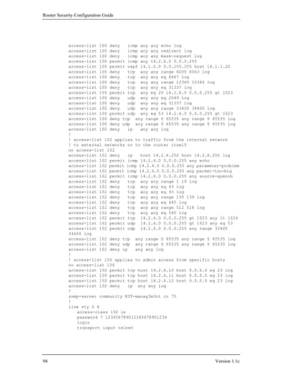
Central(config)# ip telnet source-interface loopback0
Central(config)# access-list 99 permit 14.2.9.1 log
Central(config)# access-list 99 permit 14.2.6.6 log
Central(config)# access-list 99 deny any log
Central(config)# line vty 0 4
Central(config-line)# access-class 99 in
Central(config-line)# exec-timeout 5 0
Central(config-line)# transport input telnet
Central(config-line)# login local
Central(config-line)# exec
Version 1.1c 65](https://image.slidesharecdn.com/c4-040r-02-130310054952-phpapp01/85/C4-040-r-02-65-320.jpg)
![Router Security Configuration Guide
configuration file is transferred successfully. [Note: the default Windows NT 4.0
serial communication program, Hyperterminal, performs copy/paste very slowly. On
Windows NT and 2000, use a better communication program, such as TeraTerm Pro,
if you have one available. On Linux, the minicom program is suitable for Cisco local
console access. On Solaris, the tip command can be used.]
If remote administration is being allowed and the router is running an IOS older than
version 12.0 then using the console connection or a telnet connection is the best
choice for administration. The file would again be transferred using the host systems
copy/paste buffer to move the text from a file editor to the terminal emulator.
If remote administration is allowed and the IOS is newer then version 12.0 then use
the FTP protocol to transfer the configuration files to and from the router. Set the
source interface for FTP to the loopback interface if you have defined one; otherwise
use the interface closest to the FTP server. The following example shows how to
save the startup configuration to a file.
Central# copy running-config startup-config
Central# config t
Enter configuration commands, one per line. End with CNTL/Z.
Central(config)# ip ftp username nsmith
Central(config)# ip ftp password 1pace-4ward
Central(config)# ip ftp source-interface loopback0
Central(config)# exit
Central# copy startup-config ftp:
Address or name of remote host []? 14.2.9.1
Destination filename [startup-config]? /rtr-backup/central-config
Writing central-config !!
5516 bytes copied in 12.352 secs (459 bytes/sec)
Central#
The next example demonstrates how to load a new configuration file into the startup
configuration.
Central# config t
Enter configuration commands, one per line. End with CNTL/Z.
Central(config)# ip ftp username nsmith
Central(config)# ip ftp password 1pace-4ward
Central(config)# ip ftp source-interface loopback0
Central(config)# exit
Central# copy /erase ftp: startup-config
Address or name of remote host []? 14.2.9.1
Source filename []? /rtr-backup/central-config
Destination filename [startup-config]?
Accessing ftp://14.2.9.1/rtr-backup/central-config...
Erasing the nvram filesystem will remove all files! Continue?
[confirm] y
[OK]
Erase of nvram: complete
Loading /rtr-backup/central-config !
[OK - 5516/1024 bytes]
5516 bytes copied in 4.364 secs
Central#
68 Version 1.1c](https://image.slidesharecdn.com/c4-040r-02-130310054952-phpapp01/85/C4-040-r-02-68-320.jpg)
![Advanced Security Services
The other protocols, such as rcp and TFTP, are less secure than FTP and should not
be used for loading or saving router configurations. SCP should be used whenver
possible, because it provides integrity and confidentiality protection. See Section
4.5.5 for details on using TFTP if required.
4.1.9. References
[1] Cisco IOS Release 12.0 Security Configuration Guide, Cisco Press, 1999.
This is the reference manual and guide for major security features in IOS
12.0. Relevant sections include: Security Overview, Configuring Passwords
and Privileges, and Traffic Filtering and Firewalls.
[2] Buckley, A. ed. Cisco IOS 12.0 Configuration Fundamentals, Cisco Press, 1999.
This is the reference manual and guide for basic IOS configuration tasks.
Relevant sections include: IOS User Interfaces and File Management.
[3] Albritton, J. Cisco IOS Essentials, McGraw-Hill, 1999.
An excellent introduction to basic usage and configuration of IOS routers.
[4] “Password Usage” Federal Information Processing Standard Publication 112,
National Institute of Standards and Technology, 1985.
available at: http://www.itl.nist.gov/fipspubs/fip112.htm
This federal standard includes some good guidelines on choosing passwords
that are difficult to guess.
[5] Greene, B. and Smith, P., Cisco ISP Essentials, 1st Edition, Cisco Press, April
2002.
This detailed Cisco guide for Internet Service Providers includes extensive
discussion of routing protocols (especially BGP), and an in-depth treatment
of Unicast RPF, all with fully worked-out examples.
[6] Cisco IOS Dial Services Configuration Guide, Cisco Press, 2000.
This is the reference manual and guide for serial line, modem, and dial-in
features. It includes information about configuring logins, vtys, and more.
[7] Akin, T., Hardening Cisco Routers, O’Reilly & Associates, 2002.
A pragmatic and detailed guide to securing Cisco routers. The sections about
passwords and warning banners contain very good information.
[8] Stewart, J. and Wright, J., Securing Cisco Routers: Step-by-Step, SANS
Institute, 2002.
A very specific guide to configuring many IOS features securely, especially
for initial set-up of a new router.
Version 1.1c 69](https://image.slidesharecdn.com/c4-040r-02-130310054952-phpapp01/85/C4-040-r-02-69-320.jpg)
![Router Security Configuration Guide
4.2.2. How to Disable Unneeded Features and Services
Each sub-section below describes how to disable or restrict particular services and
features under Cisco IOS 11.3 and 12.
CDP
The Cisco Discovery Protocol is a proprietary protocol that Cisco devices use to
identify each other on a LAN segment. It is useful only in specialized situations, and
is considered deleterious to security. To turn off CDP entirely, use the commands
shown below in global configuration mode.
Central# config t
Enter configuration commands, one per line. End with CNTL/Z.
Central(config)# no cdp run
Central(config)# exit
Central# show cdp
% CDP is not enabled
Central#
In the unlikely event that CDP is needed for part of a network, it can be enabled and
disabled for each interface. To enable CDP use the cdp run command in global
configuration mode, and then disable it on each interface where it is not needed using
the no cdp enable command in interface configuration mode.
TCP and UDP Small Servers
The TCP and UDP protocol standards include a recommended list of simple services
that hosts should provide. In virtually all cases, it is not necessary for routers to
support these services, and they should be disabled. The example below shows how
to test whether the TCP small servers are running, and how to disable the TCP and
UDP small servers.
Central# ! if connect succeeds, then tcp-small-servers are enabled
Central# connect 14.2.9.250 daytime
Trying 14.2.9.250, 13 ... Open
Monday, April 3, 2000 11:48:39-EDT
[Connection to 14.2.9.250 closed by foreign host]
Central# config t
Enter configuration commands, one per line. End with CNTL/Z.
Central(config)# no service tcp-small-servers
Central(config)# no service udp-small-servers
Central(config)# exit
Central# connect 14.2.9.250 daytime
Trying 14.2.9.250, 13 ...
% Connection refused by remote host
Central#
72 Version 1.1c](https://image.slidesharecdn.com/c4-040r-02-130310054952-phpapp01/85/C4-040-r-02-72-320.jpg)
![Advanced Security Services
Finger Server
The IOS finger server supports the Unix ‘finger’ protocol, which is used for querying
a host about its logged in users. On a Cisco router, the show users command may
be used to list the logged in users. Typically, users who are not authorized to log in to
the router have no need to know who is logged in. The example below shows how to
test and disable the finger server.
Central# connect 14.2.9.250 finger
Trying 14.2.9.250, 79 ... Open
This is the CENTRAL router; access restricted.
Line User Host(s) Idle Location
130 vty 0 14.2.9.6 00:00:00 goldfish
*131 vty 1 idle 00:00:00 central
[Connection to 14.2.9.250 closed by foreign host]
Central# config t
Enter configuration commands, one per line. End with CNTL/Z.
Central(config)# no ip finger
Central(config)# no service finger
Central(config)# exit
Central# connect 14.2.9.250 finger
Trying 14.2.9.250, 79 ...
% Connection refused by remote host
Central#
HTTP Server
Newer Cisco IOS releases support web-based remote administration using the HTTP
protocol. While the web access features are fairly rudimentary on most Cisco router
IOS releases, they are a viable mechanism for monitoring, configuring, and attacking
a router. If web-based remote administration is not needed, then it should be disabled
as shown below.
Central# config t
Enter configuration commands, one per line. End with CNTL/Z.
Central(config)# no ip http server
Central(config)# exit
Central# connect 14.2.9.250 www
Trying 14.2.9.250, 80 ...
% Connection refused by remote host
Central#
Web-based remote administration is useful primarily when intervening routers or
firewalls prevent use of Telnet for that purpose. However, it is important to note that
both Telnet and web-based remote administration reveal critical passwords in the
clear. Further, web-based administration imposes the requirement that users log in at
full (level 15) privilege. Therefore, web-based remote administration should be
avoided. If web-based administration is examined and found necessary for network
operations, then its use should be restricted as follows.
Version 1.1c 73](https://image.slidesharecdn.com/c4-040r-02-130310054952-phpapp01/85/C4-040-r-02-73-320.jpg)
![Advanced Security Services
description Loopback interface for service bindings
no ip proxy-arp
no ip directed-broadcast
no ip unreachable
no ip redirect
ntp disable
4.2.5. References
[1] Eldridge, B. “Building Bastion Routers Using Cisco IOS,” Phrack Magazine,
Vol. 9 Issue 55, September 1999.
available at: http://www.phrack.org/show.php?p=55&a=10
A concise and readable article with practical advice on setting up a router at a
boundary between a trusted and untrusted network.
[2] “Cisco IOS Version 12.0 Security Configuration,” National Y2K Information
Coordination Center, September 1999.
Short article with some good advice on features to turn off. Can’t seem to
find it on the web anymore, though.
[3] “Increasing Security on IP Networks,” , Cisco Internetworking Case Studies,
Cisco Systems, 1998.
available under: http://www.cisco.com/univercd/cc/td/doc/cisintwk/ics
Very helpful article from Cisco, includes common-sense measures to take on
routers running IOS 11.3. Available from Cisco’s web site.
[4] Buckley, A. Cisco IOS 12.0 Configuration Fundamentals, Cisco Press, 1999.
The sections on “Performing Basic System Management” and “Monitoring
the Router and Network” include valuable advice on how to configure basic
features and services.
[5] Cisco IOS Network Protocols Configuration Guide, Part 1, Cisco Press, 1999.
The section on “IP Addressing and Services” includes information about
several of the IP services described in this section.
[6] Held, G. and Hundley, K. Cisco Security Architectures, McGraw-Hill, New
York, 1999.
Good overview of Cisco router and TCP/IP architecture, plus excellent
coverage of access lists.
Version 1.1c 81](https://image.slidesharecdn.com/c4-040r-02-130310054952-phpapp01/85/C4-040-r-02-81-320.jpg)
![Router Security Configuration Guide
[7] Franks, J. et. al. “HTTP Authentication: Basic and Digest Access
Authentication”, RFC 2617, June 1999.
The standard for HTTP basic authentication used for access control by Cisco
IOS web remote administration.
[8] Baker, F. ed., “Requirements for IP Version 4 Routers”, RFC 1812, June 1995.
This comprehensive standard describes the services that routers must or may
provide, including several of the ones discussed in this section.
82 Version 1.1c](https://image.slidesharecdn.com/c4-040r-02-130310054952-phpapp01/85/C4-040-r-02-82-320.jpg)
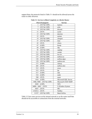
![Advanced Security Services
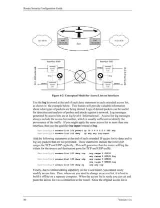
4.3. Access Control Lists, Filtering, and Rate Limiting
Cisco IOS uses access lists to separate data traffic into that which it will process
(permitted packets) and that which it will not process (denied packets). Secure
configuration of Cisco routers makes very heavy use of access lists, for restricting
access to services on the router itself, and for filtering traffic passing through the
router, and for other packet identification tasks. This section gives a moderately
detailed description of access list syntax, with some extensive examples.
4.3.1. Concepts
Access lists on Cisco routers provide packet selection and filtering capabilities. An
access list consists of one or more rules. For IP traffic, there are two types of access
lists available: standard and extended. Standard access lists only allow source IP
address filtering. Extended access lists can permit or deny packets based on their
protocols, source or destination IP addresses, source or destination TCP/UDP ports,
or ICMP or IGMP message types. Extended access lists also support selective
logging. Both standard and extended IP access lists can be applied to router
interfaces, vty lines (for remote access), IPSec, routing protocols, and many router
features. Only standard IP access lists can be applied to SNMP.
Syntax
The basic structure for an access list rule is shown below.
access-list list-number {deny | permit} condition
The access list number tells Cisco IOS which access list the rule should be a part of,
and what kind of access list it is. The condition field, which is different for each kind
of access list, specifies which packets match the rule. Conditions typically involve
protocol information and addresses, but do not involve application-level information.
The following is the syntax for a statement (rule) in a standard IP access list:
access-list list-number {deny | permit} source [source-wildcard] [log]
where list-number is the number of the access list and can be any decimal
number from 1 to 99.
deny denies access if the condition is matched.
permit permits access if the condition is matched.
source is the IP address of the network or host from which the packet
is being sent.
source-wildcard is the wildcard bits to be applied to the source.
Version 1.1c 83](https://image.slidesharecdn.com/c4-040r-02-130310054952-phpapp01/85/C4-040-r-02-83-320.jpg)
![Router Security Configuration Guide
The optional keyword log may be applied to log matches to the rule.
Note that logging for IP standard access lists is supported only in
IOS 12.0 and later.
The following is simplified syntax for a statement in an extended IP access list:
access-list list-number {deny | permit} protocol
source source-wildcard source-qualifiers
destination destination-wildcard destination-qualifiers [ log | log-input]
where list-number is the number of the access list and can be any decimal
number from 100 to 199.
deny denies access if the condition is matched.
permit permits access if the condition is matched.
protocol is the name or number of an IP-related protocol. It can be
one of the following keywords: eigrp, gre, icmp, igmp, igrp, ip,
ipinip, nos, ospf, tcp or udp. Or it can be an integer in the range 0 to
255 representing an IP protocol number. (Some protocols allow
further qualifiers: source or destination ports can be specified for tcp
or udp, and message types can be specified for icmp or igmp.)
source is the IP address of the network or host from which the packet
is being sent.
source-wildcard is the wildcard bits to be applied to the source. The
keyword any can be used in place of source and source-wildcard.
source-qualifiers are optional details on the packet source, including
port numbers and other protocol-specific information.
destination is the IP address of the network or host to which the
packet is being sent.
destination-wildcard is the IP address wildcard bits to be applied to
the destination. The keyword any can be used in place of destination
and destination-wildcard.
destination-qualifiers are optional details on the packet destination,
including port numbers and other protocol-specific information.
log, if present, causes a message about the packet that matches the
statement to be logged, and log-input causes a message that includes
the interface (logging is described in Section 4.5.1).
Cisco has also created an alternative called named IP access lists for both standard
and extended lists. This feature allows you to refer to an access list by a descriptive
name instead of by number. It also provides a convenient way to build lists on-line.
The syntax for defining an IP access list by name is shown below. After the list is
defined by name, you can add statements beginning with either the permit or deny
84 Version 1.1c](https://image.slidesharecdn.com/c4-040r-02-130310054952-phpapp01/85/C4-040-r-02-84-320.jpg)
![Router Security Configuration Guide
Routing Service
Communications between routers for routing table updates involve routing protocols.
These updates provide directions to a router on which way traffic should be routed.
You can use access lists to restrict what routes the router will accept (in) or advertise
(out) via some routing protocols. The distribute-list acl-num out command
is used to restrict routes that get distributed in routing updates, while the
distribute-list acl-num in command may be used used to filter routes that
will be accepted from incoming routing updates.
The following example shows the configuration of a standard IP access list applied
with the EIGRP routing protocol. With the access list applied, router South will not
advertise routes to the 14.2.10.0 network.
South(config)# access-list 10 deny 14.2.10.0 0.0.0.255
South(config)# access-list 10 permit any
South(config)# router eigrp 100
South(config-router)# distribute-list 10 out
South(config-router)# end
South#
Access lists can be used for general filtering of routing updates with distance-vector
routing protocols like RIP, EIGRP, and BGP. With link-state routing protocols like
OSPF, access lists can be used only for some specialized kinds of filtering. For more
information about this topic, see Section 4.4.
4.3.3. Filtering Traffic through the Router
The following examples illustrate methods to protect the router or the internal
network from attacks. Note: these separate examples should not be combined into
one access list because the result would contain contradictions. In the next section an
example configuration file is presented that shows one way to combine these
methods into access lists. Refer to the network diagram in Figure 4-1 to understand
the example interfaces, their IP addresses and the corresponding access lists.
IP Address Spoof Protection
The filtering recommendations in this sub-section are applicable to border routers,
and most interior routers. With backbone routers, it is not always feasible to define
‘inbound’ or ‘outbound’. Additional guidance and recommandations maybe found in
[6] and [11].
Inbound Traffic
Do not allow any inbound IP packet that contains an IP address from the internal
network (e.g., 14.2.6.0), any local host address (127.0.0.0/8), the link-local DHCP
default network (169.254.0.0/16), the documentation/test network (192.0.2.0/24), or
any reserved private addresses (refer to RFC 1918) in the source field. Also, if your
network does not need multicast traffic, then block the IP multicast address range
88 Version 1.1c](https://image.slidesharecdn.com/c4-040r-02-130310054952-phpapp01/85/C4-040-r-02-88-320.jpg)
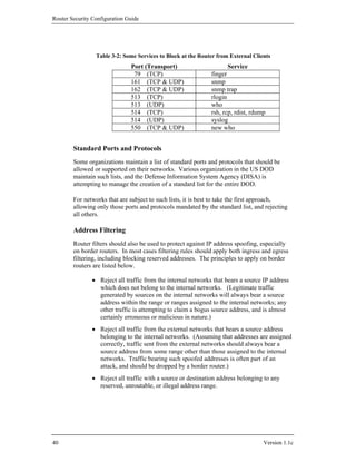
![Router Security Configuration Guide
TCP SYN Attack
The TCP SYN Attack involves transmitting a volume of connections that cannot be
completed at the destination. This attack causes the connection queues to fill up,
thereby denying service to legitimate TCP users. The following discussion shows
two different approaches.
External Access Blocked
The access list rules shown below will block packets from an external network that
have only the SYN flag set. Thus, it allows traffic from TCP connections that were
established from the internal network, and it denies anyone coming from any external
network from starting any TCP connection.
East(config)# access-list 106 permit tcp any 14.2.6.0 0.0.0.255 established
East(config)# access-list 106 deny ip any any log
East(config)# interface eth 0/0
East(config-if)# description External interface
East(config-if)# ip access-group 106 in
Limiting External Access with TCP Intercept
The access list rules shown below will block packets from unreachable hosts using
the TCP intercept feature; thus, it only allows reachable external hosts to initiate
connections to a host on the internal network. In intercept mode the router intercepts
each TCP connection establishment, and determines if the address from which the
connection is being initiated is reachable. If the host is reachable, the router allows
the connection to be established; otherwise, it prevents the connection.
East(config)# ip tcp intercept list 107
East(config)# access-list 107 permit tcp any 14.2.6.0 0.0.0.255
East(config)# access-list 107 deny ip any any log
East(config)# interface eth0
East(config-if)# description External ethernet interface to 14.1.0.0 net
East(config-if)# ip access-group 107 in
East(config-if)# exit
TCP intercept is a very effective mechanism for protecting hosts on a network from
outside TCP SYN attacks, for extensive details consult the Cisco IOS 12 Security
Configuration Guide [5]. The TCP intercept feature is available in most, but not all,
Cisco IOS version 12.0 and later releases. Note that TCP intercept, while it can be
very useful, can also impose significant overhead on router operations. Examine and
test the performance burden imposed by TCP intercept before using it on an
operational network.
Land Attack
The Land Attack involves sending a packet to the router with the same IP address in
the source and destination address fields and with the same port number in the source
90 Version 1.1c](https://image.slidesharecdn.com/c4-040r-02-130310054952-phpapp01/85/C4-040-r-02-90-320.jpg)
![Router Security Configuration Guide
East(config)# access-list 102 permit icmp any any echo
East(config)# access-list 102 permit icmp any any parameter-problem
East(config)# access-list 102 permit icmp any any packet-too-big
East(config)# access-list 102 permit icmp any any source-quench
East(config)# access-list 102 deny icmp any any log
Another program that deals with certain ICMP message types is traceroute.
Traceroute is a utility that prints the IP addresses of the routers that handle a packet
as the packet hops along the network from source to destination. On Unix and Linux
operating systems, traceroute uses UDP packets and causes routers along the path to
generate ICMP message types ‘Time Exceeded’ and ‘Unreachable’. An attacker can
use traceroute response to create a map of the subnets and hosts behind the router,
just as they could do with ping’s ICMP Echo Reply messages. Therefore, block
naïve inbound traceroute by including a rule in the inbound interface access list, as
shown in the example below (ports 33400 through 34400 are the UDP ports
commonly used for traceroute).
East(config)# access-list 100 deny udp any any range 33400 34400 log
A router may be configured to allow outbound traceroute by adding a rule to the
outbound interface access list, as shown in the example below.
East(config)# access-list 102 permit udp any any range 33400 34400 log
Distributed Denial of Service (DDoS) Attacks
Several high-profile DDoS attacks have been observed on the Internet. While routers
cannot prevent DDoS attacks in general, it is usually sound security practice to
discourage the activities of specific DDoS agents (a.k.a. zombies) by adding access
list rules that block their particular ports. The example below shows access list rules
for blocking several popular DDoS attack tools. [Note that these rules might also
impose a slight impact on normal users, because they block high-numbered ports that
legitimate network clients may randomly select. You may choose to apply these
rules only when an attack has been detected. Otherwise, they would be applied to
traffic in both directions between an trusted network and an untrusted network.]
! the TRINOO DDoS systems
access-list 170 deny tcp any any eq 27665 log
access-list 170 deny udp any any eq 31335 log
access-list 170 deny udp any any eq 27444 log
! the Stacheldraht DDoS system
access-list 170 deny tcp any any eq 16660 log
access-list 170 deny tcp any any eq 65000 log
! the TrinityV3 system
access-list 170 deny tcp any any eq 33270 log
access-list 170 deny tcp any any eq 39168 log
! the Subseven DDoS system and some variants
access-list 170 deny tcp any any range 6711 6712 log
access-list 170 deny tcp any any eq 6776 log
access-list 170 deny tcp any any eq 6669 log
access-list 170 deny tcp any any eq 2222 log
access-list 170 deny tcp any any eq 7000 log
92 Version 1.1c](https://image.slidesharecdn.com/c4-040r-02-130310054952-phpapp01/85/C4-040-r-02-92-320.jpg)
![Advanced Security Services
4.3.5. Turbo Access Control Lists
Some Cisco router models support compiled access control lists, called “Turbo
ACLs”, in IOS 12.1(6), and later. Using compiled access control lists can greatly
reduce the performance impact of long lists. To enable turbo access lists on a router,
use the configuration mode command access-list compiled. (If your IOS does
not support compiled access lists, the command will generate a harmless error
message.) Once this facility is enabled, IOS will automatically compile all suitable
access lists into fast lookup tables while preserving their matching semantics. Once
you have enabled turbo access lists, you can view statistics about them using the
command show access-list compiled. If you use access lists with six or more
rules on high-speed interfaces, then compiled ACLs can give improved performance.
4.3.6. Rate Limiting with Committed Access Rate
Committed Access Rate (CAR) is a router service that gives administrators some
control over the general cross-section of traffic entering and leaving a router. By
allocating a specific amount of bandwidth to defined traffic aggregates, data passing
through the router can be manipulated to preserve fragile traffic, eliminate excessive
traffic, and limit spoofed traffic; however, the most important task that CAR can
perform is to mitigate the paralyzing effects of DoS attacks and flash crowds.
You can use CAR to reserve a portion of a link’s bandwidth for vital traffic, or to
limit the amount of bandwidth consumed by a particular kind of attack. In the latter
case, it may not be necessary to keep CAR rules in place at all times, but to be ready
to apply them quickly when you detect an attack in progress. This short section gives
an overview of CAR, and a few simple examples.
CAR Command Syntax
Configuring CAR requires you to apply rate limiting rules to each interface where
you enforce constraints on traffic or bandwidth usage. Each interface can have a
separate, ordered set of rules for the in-bound (receiving) and out-bound (sending)
directions. The general syntax for a CAR rule is shown below, somewhat simplified.
rate-limit {input | output} [access-group [rate-limit] acl]
token-bit-rate burst-normal-size burst-excess-size
conform-action action exceed-action action
To add a rule to an interface, simply type the rule in interface configuration mode, as
shown in the examples below. To remove a rule, enter it again adding the keyword
no to the front. To view the CAR rules on all the interfaces, use the command show
interface rate-limit. The output of the command will show both the rules and
some traffic statistics about the rate limiting. A sample of the output is included in
the first example below.
For more information on CAR commands, consult the “IOS Quality of Service
Solutions Command Reference” section of the IOS documentation.
Version 1.1c 95](https://image.slidesharecdn.com/c4-040r-02-130310054952-phpapp01/85/C4-040-r-02-95-320.jpg)
![Router Security Configuration Guide
Defining Rules
Each rate limit rule is made up of 3 parts: the aggregate definition, the token bucket
parameters, and the action specifications.
• The aggregate definition section of a rule defines the kind of traffic (or
“packet aggregate”) to which the rule applies. The aggregate definition
must include the traffic direction, and may also include fine-grained traffic
selection specified with an access control list. If the rule is meant to apply
to packets entering the router, use the input keyword; for packets leaving
the router use the output keyword. If the aggregate definition includes
an access-group clause, then the CAR rule will apply only to traffic that
is permitted by or matches that access list; if you supply no access-group
clause then the rule applies to all traffic. [It is also possible to apply CAR
rules to packets by QoS header and other criteria, but that is outside the
scope of this brief discussion.] If the keyword rate-limit appears, it
indicates that the aggregate is defined by a rate-limit access list, otherwise
the access list should be a standard or extended IP access list. Rate-limit
access lists define aggregates based on IP precedence or MAC addresses.
• The second part of the rate-limit command is comprised of the three token
bucket parameters. The CAR facility uses a token bucket model to
allocate or limit bandwidth of traffic. This model gives you a flexible
method to stipulate bounds of traffic behavior for an aggregate. The token
bucket model needs three parameters for configuration: the token bit rate,
the traffic burst normal size (in bytes), and the traffic burst exccess size.
The token bit rate parameter must be specified in bits per second (bps), and
must be greater than 8000. It generally describes the allowed rate for the
aggregate. The burst normal size, given in bytes, is generally the size of a
typical traffic transaction in a single direction. For simple protocols, such
as ICMP or DNS, it would simply be the size of a typical message. The
burst excess size denotes the upper bound or maximum size expected for
traffic bursts, before the aggregate uses up its allocated bandwidth. For a
more detailed description of the token bucket model, consult [9].
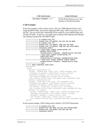
• The last section of a rule consists of the two action specifications. The
first action instructs the router on how to handle packets when the
aggregate conforms to bandwidth allocation, and the second how to handle
packets when the aggregate exceeds its bandwidth allocation. Depending
on your IOS version, there may be as many as nine possible actions; the
most commonly used four are described below.
CAR Action Syntax Action Performed
drop Discard the packet.
transmit Transmit or forward the packet.
continue Apply the next rate-limit rule.
96 Version 1.1c](https://image.slidesharecdn.com/c4-040r-02-130310054952-phpapp01/85/C4-040-r-02-96-320.jpg)
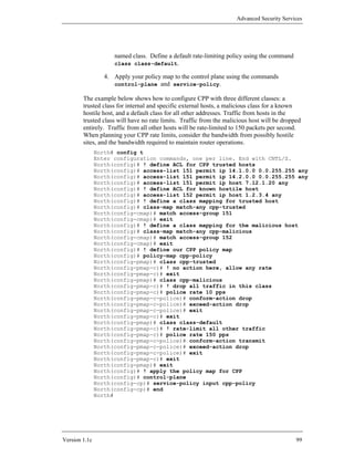
![Router Security Configuration Guide
North(config-if)# rate-limit input access-group 160
64000 8000 8000
conform-action transmit exceed-action drop
North(config-if)# end
North#
The CAR rule in this example simply discards excessive TCP SYN packets. In this
case, legitimate traffic would also be affected. If you knew the general source of the
attack (perhaps an IP address range) then you could make the defense more selective
by incorporating the address range into the aggregate definition access list. For
another example of using CAR to combat a DoS attack, consult [10].
4.3.7. Control Plane Policing (CPP)
Conceptually, router operations can be abstracted into three planes: forwarding,
control, and management. The forwarding plane (also called the “data” plane)
forwards user data packets through the router. The management plane consists of
traffic for configuring and monitoring router operations. The control plane consists of
the routing, signaling and link management protocols. Timely and reliable operation
of the management and control planes are essential for maintaining the flow of traffic
through the forwarding plane.
Control Plane Policing (CPP) is a Cisco IOS feature that you can employ to counter
resource starvation-based DoS attacks that target the central processor of a router
(control plane and management plane). CPP protects the central processor via
policies that filter or rate limit traffic directed to the processor. Detailed information
about CPP may be found in a Cisco white paper [12].
To implement a CPP policy, all traffic destined for the control plane of a router must
be categorized into network administrator-defined groups or classes (e.g. the
“critical,” “normal,” “malicious,” and “default” classes). Then service policies
should be created and applied that cause traffic classes destined for the route
processor to be accepted, discarded, or rate limited. Take care when defining and
applying CPP policy -- it is easy to accidentally restrict the wrong traffic and disrupt
management or control plane services.
Before attempting to configure CPP, identify the classes you wish to handle, and
rough traffic rate limits for each of them. Once you have defined your classes,
setting up control plane policing on IOS requires four steps.
1. Create access lists that match (permit) the traffic from members of each
class. (If you have a ‘default’ class, do not create an access list for it.)
2. Define a named class map for each of the access lists you created in step
1, using the class-map command.
3. Create a policy map using the policy-map command. In the map, use
the class map-name command to define rate-limiting policy for each
98 Version 1.1c](https://image.slidesharecdn.com/c4-040r-02-130310054952-phpapp01/85/C4-040-r-02-98-320.jpg)
![Router Security Configuration Guide
To view the current CPP policy and traffic statistics, use the command
show policy-map control-plane.
To remove a CPP policy, use the command no service-policy command as
shown below.
North(config)# control-plane
North(config-cp)# no service-policy input cpp-policy
North(config-cp)# end
North#
4.3.8. References
[1] Chapman, D. Brent and Zwicky, Elizabeth D., Building Internet Firewalls,
O’Reilly Associates, 1995.
This text provides valuable information on how to packet filter many of the
commonly used services, e.g., SMTP, FTP, Telnet, etc.
[2] Karrenberg, D., Moskowitz, B. and Rekhter, Y. “Address Allocation for Private
Internets”, RFC 1918, February 1996.
This RFC describes the IP address allocation for private intranets. The
Internet Assigned Numbers Authority has reserved the following three blocks
of the IP address space for private intranets: 10.0.0.0 - 10.255.255.255,
172.16.0.0 - 172.31.255.255, and 192.168.0.0 - 192.168.255.255.
[3] Held, G., and Hundley, K., Cisco Access List Field Guide, McGraw-Hill, 1999.
This book offers detailed information about access control lists and many
examples of list syntax and usage.
[4] Held, G., and Hundley, K., Cisco Security Architectures, McGraw-Hill, 1999
This book includes a good introduction to router security, and a good primer
on access lists
[5] Cisco IOS Release 12.0 Security Configuration Guide, Cisco Press, 1999.
This is the reference manual and guide for major security features in IOS
12.0. It includes information on TCP Intercept, reflexive access lists, and
dynamic access lists.
[6] Ferguson, P. and Senie, D. “Network Ingress Filtering: Defeating Denial of
Service Attacks which employ IP Source Address Spoofing”, RFC 2827, 2000.
This Internet ‘Best Current Practice’ RFC gives a good overview of source
address filtering.
100 Version 1.1c](https://image.slidesharecdn.com/c4-040r-02-130310054952-phpapp01/85/C4-040-r-02-100-320.jpg)
![Advanced Security Services
[7] Greene, B. and Smith, P., Cisco ISP Essentials, 1st Edition, Cisco Press, April
2002.
This detailed Cisco guide for Internet Service Providers includes extensive
discussion of routing protocols (especially BGP), and an in-depth treatment
of Unicast RPF, all with fully worked-out examples.
[8] Sedayao, J., Cisco IOS Access Lists, O’Reilly Associates, 2001.
A detailed guide to access lists, including coverage of using access lists with
routing protocols.
[9] “Selecting Burst and Extended Burst Values for Class-based Policing”, Cisco
Tech Note, Cisco Systems, Feb 2002.
available at:
http://www.cisco.com/warp/public/105/carburstvalues.html
Describes the CAR token bucket model and burst size parameters in some
depth; gives guidance on how to select usable values.
[10] “Using CAR During DOS Attacks”, Cisco Tech Note, Cisco Systems, 2001.
available at:
http://www.cisco.com/warp/public/63/car_rate_limit_icmp.pdf
Walks through a detailed CAR example related to ICMP flooding.
[11] Baker, F. and Savola, P., “Ingress Filtering for Multihomed Networks”, RFC
3704, March 2004.
Detailed directions for doing RFC 2827-compliant filtering on networks
connected to multiple providers.
[12] “Deploying Control Plane Policing”, Cisco white paper, Cisco Systems, 2005.
available under: http://www.cisco.com/en/US/products/
ps6642/prod_white_papers_list.html
This white paper explains the motivations for CPP and provides detailed
instructions on how to configure it. It also lists the Cisco IOS releases that
support CPP.
Version 1.1c 101](https://image.slidesharecdn.com/c4-040r-02-130310054952-phpapp01/85/C4-040-r-02-101-320.jpg)
![Router Security Configuration Guide
4.4. Routing and Routing Protocols
“A protocol is a formal description of a set of rules and conventions that govern how
devices on a network exchange information.”[5] This section will discuss two basic
types of protocols, with a focus on the latter. The two types of protocols are:
• Routed protocols –
These are protocols that can be routed by a router. The routed protocol
allows the router to correctly interpret the logical network. Some examples
of routed protocols are IP, IPX, AppleTalk, and DECnet.
• Routing protocols –
“A routing protocol gathers information about available networks and the
distance, or cost, to reach those networks.”[7] These protocols support
routed protocols and are used to maintain routing tables. Some examples
of routing protocols are OSPF, RIP, BGP, IS-IS, and EIGRP.
All of the examples in this section are based on the sample network architecture
shown in Figure 4-1.
Routed Protocols
The most commonly used routed network protocol suite is the TCP/IP suite; its
foundation is the Internet Protocol (IP). This section will not provide an in-depth
discussion of this protocol, as that is far beyond the scope of this guide, consult [6]
for a detailed introduction. ARPA sponsored the development of IP over twenty-five
years ago under the ARPANET project. Today, it is the basis for the worldwide
Internet. Its growth and popularity can be attributed to IP’s ability to connect
different networks regardless of physical environment, and the flexible and open
nature of the IP network architecture.
IP is designed for use on large networks; using IP, a connected host anywhere on a
network can communicate with any other. In practice, host applications almost never
use raw IP to communicate. Instead, they use one of two transport-layer protocols
built on top of IP: the Transmission Control Protocol (TCP) or the User Datagram
Protocol (UDP). Use of TCP or UDP is immaterial to routing, which takes place
exclusively at the network layer. Each IP host does not need to know a path through
the network to every other host, instead it only needs to know the address of one or a
small number of routers. These routers are responsible for directing each IP packet to
its intended destination.
In a small network, each router can simply be connected directly to every other
router. For larger networks, of course, connecting every router to every other would
be prohibitively expensive. Instead, each router maintains a route table with
information about how to forward packets to their destination addresses. Correct,
efficient, and secure operation of any large IP network depends on the integrity of its
route tables. For a detailed introduction to the concepts of routing, consult [16].
102 Version 1.1c](https://image.slidesharecdn.com/c4-040r-02-130310054952-phpapp01/85/C4-040-r-02-102-320.jpg)
![Router Security Configuration Guide
Open Shortest Path First, and IS-IS, Intermediate-System to Intermediate-System, are
examples of link state interior gateway protocols. BGP-4, the Border Gateway
Protocol, version 4, is the IETF standard exterior gateway protocol. EIGRP, the
Enhanced Interior Gateway Routing Protocol, is a proprietary Cisco IGP that is
sometimes used in all-Cisco networks. The table below provides a short comparison.
Table 4-2 – Five Popular IP Routing Protocols
RIP Distance vector protocol: maintains a list of distances to other networks
measured in hops, the number of routers a packet must traverse to reach its
destination. RIP is suitable only for small networks, partly because the
maximum distance is 15 hops. Broadcasts updates every 30 seconds to
neighboring RIP routers to maintain integrity. Each update is a full route table.
OSPF Link state protocol: uses a link speed-based metric to determine paths to other
networks. Each router maintains a simplified map of the entire network.
Updates are sent via multicast, and are sent only when the network
configuration changes. Each update only includes changes to the network.
OSPF is suitable for large networks.
IS-IS Link state protocol: uses a cost-based metric by default to determine paths to
other networks. Optional metrics are delay, expense and error. Cisco IOS
supports only the cost based metric. Routers establish and maintain neighbor
adjacencies every 10 seconds by default. A complete link state database is
broadcast by a designated router every 10 seconds by default to synchronize
neighbor route tables. IS-IS is suitable for large networks.
EIGRP Distance vector protocol: maintains a complex set of metrics for the distance to
other networks,and incorporates some features of link state protocols.
Broadcasts updates every 90 seconds to all EIGRP neighbors. Each update
includes only changes to the network. EIGRP is suitable for large networks.
BGP A distance vector exterior gateway protocol that employs a sophisticated series
of rules to maintain paths to other networks. Updates are sent over TCP
connections between specifically identified peers. BGP-4 employs route
aggregation to support extremely large networks (e.g. the Internet).
Another important aspect of a routing protocol scheme is the amount of time it takes
for network architecture or connectivity changes to be reflected in the route tables of
all affected routers. This is usually called the rate of convergence. For example, in a
large network OSPF offers much faster convergence than RIP.
Configuring routing in IP networks can be a very complex task, and one which is
outside the scope of this guide. Routing does raise several security issues, and Cisco
IOS offers several security services for routing; this section discusses some of these
security issues and describes several of the security services in moderate detail. For
general guidance on routing protocols, consult the Cisco IOS documentation, or [3].
4.4.1. Common routing hazards
A question that is often overlooked is “Why do we need to concern ourselves with
security of the network?” A better question to ask would be “What kind of damage
104 Version 1.1c](https://image.slidesharecdn.com/c4-040r-02-130310054952-phpapp01/85/C4-040-r-02-104-320.jpg)
![Advanced Security Services
could an adversary do to our network?” Section 3 presents some motivations for
overall router security. This section focuses on security issues related to routing and
routing protocols. Routing security should be a top priority for network
administrators who want to:
• prevent unauthorized access to resources on the network,
• protect mission information from unauthorized exposure and modification,
• prevent network failures and interruptions in service.
An unprotected router or routing domain makes an easy target for any network-savvy
adversary. For example, an attacker who sends false routing update packets to an
unprotected router can easily corrupt its route table. By doing this, the attacker can
re-route network traffic in whatever manner he desires. The key to preventing such
an attack is to protect the route tables from unauthorized and malicious changes.
There are two basic approaches available for protecting route table integrity:
1. Use only static routes –
This may work in small networks, but is unsuitable for large networks
because it increases administrative overhead and requires administrative
response to any failures.
2. Authenticate route table updates –
By using routing protocols with authentication, network administrators
can deter attacks based on unauthorized routing changes. Authenticated
router updates ensure that the update messages came from legitimate
sources, bogus messages are automatically discarded.
Another form of attack an adversary might attempt against a router is a denial of
service attack. This can be accomplished in many different ways. For example,
preventing router update messages from being sent or received will result in bringing
down parts of a network. To resist denial of service attacks, and recover from them
quickly, routers need rapid convergence and backup routes.
A detailed analysis of routing protocol threats and countermeasures may be found in
a Cisco SAFE white paper [45].
4.4.2. ARP and LANs
Address Resolution Protocol, or ARP, is the protocol used to map IP addresses to a
particular MAC or Ethernet address. ARP is described in more detail in RFC 826 and
Parkhurst [2]. Proxy ARP is a method of routing packets using the Ethernet MAC
address instead of the IP address to determine the final destination of a packet. For a
detailed description of Proxy ARP, consult RFC 1027.
However, because ARP offers no security, neither does Proxy ARP. The fundamental
security weakness of ARP is that it was not designed to use any form of
authentication. Anyone on a LAN segment can modify an entry in the ARP cache of
Version 1.1c 105](https://image.slidesharecdn.com/c4-040r-02-130310054952-phpapp01/85/C4-040-r-02-105-320.jpg)
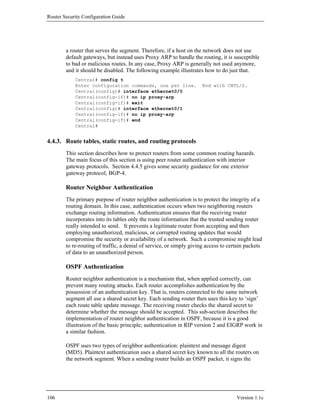
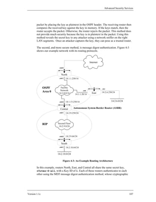
![Router Security Configuration Guide
authentication type is denoted by a value of 2. Figure 4-4 shows how East
authenticates to North. East first builds an OSPF packet, both header and body. It
then picks a primary key to use on the network segment. In this case, the key is
r0utes-4-all. The corresponding Key ID, 1, is placed in the header. East also
places a 32-bit sequence number in the header. This sequence number protects
against replay attacks so that no two OSPF packets will have the same hash value.
The sequence number is incremented with every new packet. Finally, the secret key
is appended to the packet. East runs the cryptographic hash algorithm, MD5, against
the OSPF packet. The output, 16 bytes, is written over the secret that was appended
to the packet.
The receiving router, North, looks at the Key ID to determine which key was used to
generate the hash, or signature. The router then uses its own key to regenerate the
hash on the received packet in the same manner as the sending router. If the
regenerated hash matches the hash that was sent from East, then the North trusts the
packet. Otherwise, it rejects the packet as being invalid.
OSPF Version OSPF pkt type OSPF Version OSPF pkt type
OSPF length OSPF length
Source OSPF Router ID Source OSPF Router ID
OSPF Area ID OSPF Area ID
0 (no checksum) 0 (no checksum)
2 (cryptographic auth type) 2 (cryptographic auth type)
0 0
1 (Key ID) 16 (MD5 len) 1 (Key ID) 16 (MD5 len)
MD5 hash
Cryptographic sequence number Cryptographic sequence number
algorithm
OSPF packet body OSPF packet body
MD5
16-byte secret
cryptographic
hash
Figure 4-4: OSPF Calculation of an MD5 Authentication Signature (from [4])
OSPF Plaintext Authentication
This method is not recommended, use the superior MD5 method.
108 Version 1.1c](https://image.slidesharecdn.com/c4-040r-02-130310054952-phpapp01/85/C4-040-r-02-108-320.jpg)
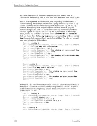
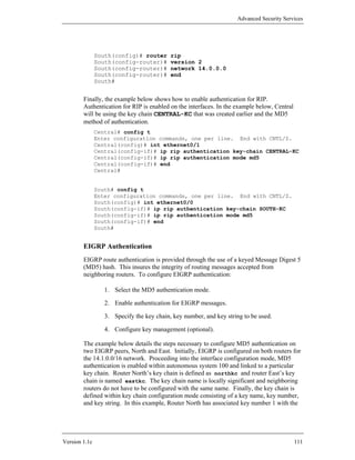
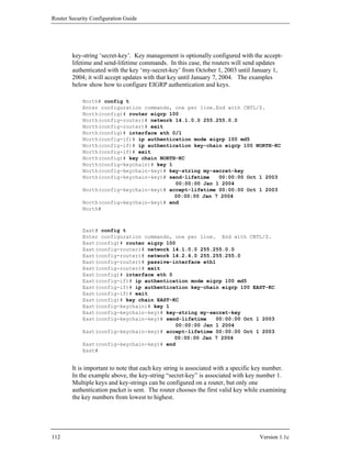
![Advanced Security Services
IS-IS Authentication
IS-IS provides three methods of authentication to prevent routing attacks: Plaintext
(or clear text), Enhanced Clear Text and Hashed Message Authentication Code
Message Digest 5 (HMAC-MD5). Plaintext authentication uses a shared secret key
known to all the routers on the network segment. This method does not provide much
security because the key is in plaintext in the packet. Using this method reveals the
secret key to any attacker using a network sniffer on the associated LAN segments.
Once an attacker captures the key, they can pose as a trusted router. Enhanced Clear
Text authentication functions like Plaintext authentication with the exception that the
authenticating key is encrypted only within the configuration of the router. The final,
and recommended security practice is to use HMAC-MD5 authentication. This
method sends a “message digest” instead of the authenticating key itself. The
message digest is created using a shared secret key and a message, but the key itself
is not sent, preventing it from being read while it is being transmitted.
The IS-IS HMAC-MD5 authentication feature adds an HMAC-MD5 digest to each
IS-IS protocol data unit (PDU) packet before transmitting the packet across the
network. The digest is used by the receiving router(s) to authenticate each PDU. This
process prevents unauthorized PDUs from being accepted and used in the IS-IS
routing domain.
IS-IS has five PDU packet types: LSP, LAN Hello, Serial Hello CNSP and PSNP.
The IS-IS HMAC-MD5 authentication can be applied to all five types of PDU. The
authentication can be enabled on the two different IS-IS Levels (Level 1 and Level 2)
independently. “The interface-related PDUs (LAN Hello, Serial Hello, CNSP and
PSNP) can be enabled with authentication on different interfaces, with different
levels and different passwords.” [26]
In order to use IS-IS HMAC-MD5 authentication, you must configure the following
three things:
1. a key chain,
2. an IS-IS routing protocol instance, and
3. HMAC-MD5 authentication.
The keys on the key chain must be identical on neighboring routers. Each sending
router uses its keys to generate the cryptographic hash incorporated into IS-IS
messages. The receiving router then uses its identical set of keys to check the IS-IS
authentication. The transcripts below show routers from Figure 4-5, North and East,
being configured with the key my-secret-key, in their respective key chains.
North# config t
Enter configuration commands, one per line. End with CNTL/Z.
North(config)# key chain ISIS-KC
North(config-keychain)# key 1
North(config-keychain-key)# key-string my-secret-key
North(config-keychain-key)# end
North#
Version 1.1c 113](https://image.slidesharecdn.com/c4-040r-02-130310054952-phpapp01/85/C4-040-r-02-113-320.jpg)
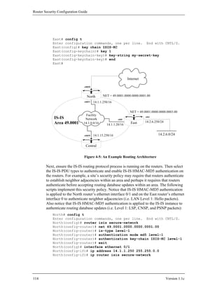
![Advanced Security Services
North(config-if)# isis authentication mode md5 level-1
North(config-if)# isis authentication key-chain ISIS-KC level-1
North(config-if)# end
North#
East# config t
Enter configuration commands, one per line. End with CNTL/Z.
East(config)# router isis secure-network
East(config-router)# net 49.0001.0000.0000.0003.00
East(config-router)# is-type level-1
East(config-router)# authentication mode md5 level-1
East(config-router)# authentication key-chain ISIS-KC level-1
East(config-router)# exit
East(config)# interface ethernet 0
East(config-if)# ip address 14.1.1.20 255.255.0.0
East(config-if)# ip router isis secure-network
East(config-if)# isis authentication mode md5 level-1
East(config-if)# isis authentication key-chain ISIS-KC level-1
East(config-if)# end
East#
Authentication on Level 2 packets is accomplished by changing the level-1 parameter
in the example above to level-2.
IS-IS offers a unique security advantage compared to other IP routing protocols. IS-
IS packets are encapsulated over the data link and are not carried in IP packets.
Therefore an attacker has to be physically attached to a router in the IS-IS network to
maliciously disrupt the IS-IS routing environment. “Other routing protocols, such as
RIP, OSPF and BGP, are susceptible to attacks from remote IP networks through the
Internet because routing protocol packets are ultimately embedded in IP packets,
which makes them susceptible to remote access by intrusive applications.” [27]
Key Management
The strength of these methods, RIP, OSPF, IS-IS, and EIGRP routing update
authentication, depends on two factors: the secrecy of the keys and the quality of the
keys. A key’s secrecy is intact only if it is known by the trusted routers but hidden
from any attacker. The best method for distributing keys to trusted routers is to do it
manually. The other issue with maintaining secrecy is the question of “How many
keys should be used in the routing domain?” That is, whether one key should be used
for the entire routing domain, or a separate key for each router neighbor-to-neighbor
connection. Using a separate key for each router neighbor-to-neighbor connection
can become an administrative nightmare, so using a common key for the entire
routing domain is recommended. However, maintaining the secrecy of the key
becomes much more important, because failure to do so can compromise the entire
network. Key lifetime is also important. RIP, IS-IS, and EIGRP use Cisco IOS key
chains, which offer substantial control over key lifetime. OSPF uses single keys; an
administrator must manually change the keys when their lifetimes expire.
Version 1.1c 115](https://image.slidesharecdn.com/c4-040r-02-130310054952-phpapp01/85/C4-040-r-02-115-320.jpg)
![Router Security Configuration Guide
Management of key lifetime is accomplished optionally through the use of the
keychain accept-lifetime and send-lifetime commands. Both of these are
configured within the key chain configuration mode, and specify the start-time and
end-time to accept and send individual keys. These commands apply to keys in a
keychain, so they can be used for IS-IS, EIGRP, and RIPv2 authentication, but not
OSPF authentication. The router must be configured to maintain correct time (see
Section 4.5.2). The number of different keys and the key validity periods should be
defined in the router security policy.
The other factor that authentication relies upon is the quality of the keys. The rules
for generating good passwords apply to generating good keys as well. See Section 4.1
for a detailed description.
If you use routing update authentication, then your router security policy should
define the key management procedures and responsibilities.
Static Routes
Static routes are manually configured on the router as the only path to a given
destination. These routes typically take precedence over routes chosen by dynamic
routing protocols.
In one sense, static routes are very secure. They are not vulnerable to spoofing
attacks because they do not deal with router update packets. Using static routes
exclusively can make network administration very difficult. Also, configuring a
large network to use only static routes can make the availability of large pieces of the
network subject to single points of failure. Static routes cannot easily handle events
that change the network topology, such as link failures. A dynamic routing protocol,
such as OSPF, can correctly re-route traffic in the case of a router or link failure.
In most cases, static routes take precedence over their dynamic counterparts.
However, if an administrative distance is specified, then that static route can be
overridden by dynamic information. For example, OSPF-derived routes have a
default administrative distance of 110. Thus a static route must have an
administrative distance greater than 110 if the OSPF derived route is to have
precedence over the static route. Static routes have a default administrative distance
of 1.
The following example illustrates how to create a static route with a higher
administrative distance than OSPF. For more information on the internal workings of
static routes, consult [7].
Central# config t
Enter configuration commands, one per line. End with CNTL/Z.
Central(config)# ip route 14.2.6.0 255.255.255.0 14.1.1.20 120
Central(config)# end
Central#
116 Version 1.1c](https://image.slidesharecdn.com/c4-040r-02-130310054952-phpapp01/85/C4-040-r-02-116-320.jpg)
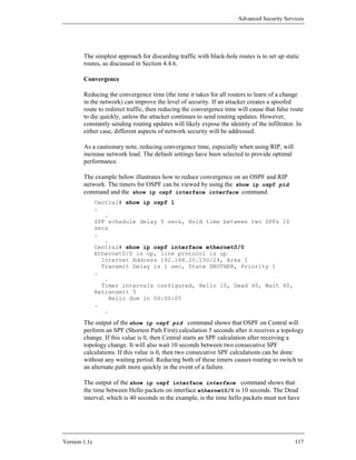
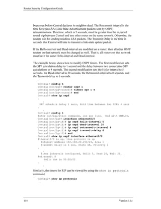
![Advanced Security Services
.
Routing Protocol is "rip"
Sending updates every 30 seconds, next due in 22 seconds
Invalid after 180 seconds, hold down 180, flushed after 240
.
.
In its current configuration, RIP routing updates are sent every 30 seconds. If no
update is received within 180 seconds, then the route is declared invalid. The hold
down time is the time that a route will remain in the routing table before a new route
is accepted. The flush time is the amount of time that a route will remain in the
routing table before it is removed if no update to that route is received. The sleep
time, which is not shown, is the amount of time, measured in milliseconds, an update
will be delayed before transmission. The example shows how to modify the RIP
timers.
Central# config t
Enter configuration commands, one per line. End with CNTL/Z.
Central(config)# router rip
Central(config-router)# timers basic 20 120 150 230 3
Central(config-router)# end
Central# show ip protocols
.
.
Routing Protocol is "rip"
Sending updates every 20 seconds, next due in 6 seconds
Invalid after 120 seconds, hold down 150, flushed after 230
.
.
Central#
In general, OSPF and IS-IS are preferable to RIP. It is also possible to redistribute
OSPF or IS-IS routes over RIP, and this is preferable to running RIP on an entire
large network. For details on this topic, consult Chapter 13 of [2].
4.4.4. Disabling unneeded routing-related services
Passive Interfaces
The passive-interface command is used to prevent other routers on the network
from learning about routes dynamically. It can also be used to keep any unnecessary
parties from learning about the existence of certain routes or routing protocols used.
It is typically used when the wildcard specification on the network router
configuration command configures more interfaces than desirable. The example
below illustrates such a case.
Router1# show config
.
.
interface ethernet0
description Active routing interface for 14.1.0.0 net
ip address 14.1.15.250 255.255.0.0
!
Version 1.1c 119](https://image.slidesharecdn.com/c4-040r-02-130310054952-phpapp01/85/C4-040-r-02-119-320.jpg)
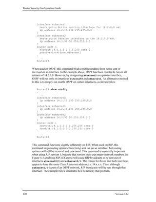
![Advanced Security Services
Central# config t
Enter configuration commands, one per line. End with CNTL/Z.
Central(config)# router rip
Central(config-router)# passive-interface ethernet0/0
Central(config-router)# end
Central#
The syntax for using this command on OSPF is nearly identical. The example below
illustrates that, however, since OSPF is not enabled on the interface to the RIP
network, this step is unnecessary. Therefore, the following example is for illustration
purposes only.
Central# config t
Enter configuration commands, one per line. End with CNTL/Z.
Central(config)# router ospf 1
Central(config-router)# passive-interface ethernet0/1
Central(config-router)# end
Central#
Using filters to block routing updates
The distribute-list command is used to apply access lists on routing protocols.
This command has two primary functions. To suppress advertisements of particular
networks in updates, use the distribute-list out command . To filter the
receipt of network updates, use the distribute-list in command. Each
command behaves differently with respect to the routing protocol used.
To apply this command to a routing protocol, you must first create an access list. For
more information about how to create access lists, see Section 4.3. For illustration
purposes, an access list with rules filtering out 14.2.10.0/24 will be used.
Central# config t
Enter configuration commands, one per line. End with CNTL/Z.
Central(config)# access-list 55 deny 14.2.10.0 0.0.0.255
Central(config)# access-list 55 permit any
Central(config)# end
Central#
The OSPF distribute-list in configuration command prevents routes from
being inserted into the routing table, but it does not stop routes from being sent out in
the link-state advertisements (LSAs). Thus all downstream routers will learn about
the networks that were supposed to be filtered in these LSAs. Some authors,
including Parkhurst [2], advise against using distribute-list in for OSPF.
The distribute-list out command in OSPF configuration mode stops routes
from being advertised in updates. However, this restriction only applies to external
routes, that is, routes from a different autonomous system (AS). The following
example shows how to prevent Central from advertising the 14.2.10.0 network from
the RIP routing domain into the OSPF routing domain. With this setting North and
East would not see a route to the 14.2.10.0 network.
Version 1.1c 121](https://image.slidesharecdn.com/c4-040r-02-130310054952-phpapp01/85/C4-040-r-02-121-320.jpg)
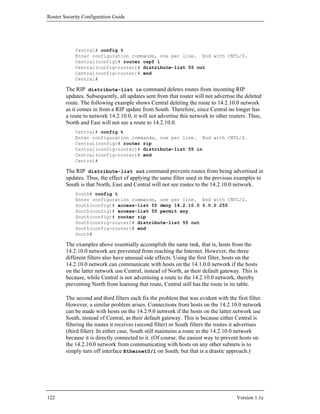
![Advanced Security Services
Migrating from RIP to OSPF: Security issues and concerns
Although RIP has withstood the test of time and proven itself to be a reliable routing
protocol, OSPF is the superior routing protocol. Both protocols are supported by
virtually every routing vendor, but OSPF offers better scaling and faster convergence.
If support for RIP is not an essential requirement, then migrating to OSPF is the
recommended solution. While both protocols support authentication, OSPF offers
better convergence times, and using OSPF reduces the likelihood of accidentally
sending out routing update packets on an unintended interface. Migration procedures
are beyond the scope of this document, see [2] for detailed directions. However, an
important step to remember is to remove RIP after OSPF has been enabled. Failure to
do so will not cause a routing failure, but an attacker could then take advantage of
RIP and insert a malicious route into the routing table. The example below shows
how to turn off RIP. Remember to turn off RIP on all the routers after migration.
Central(config)# no router rip
Central(config)#
After disabling RIP, check the configured protocols using the command
show ip protocols.
4.4.5. Exterior Gateway Routing Protocol Security
Configuring an exterior gateway protocol can be very complex, and is outside the
scope of this guide. This sub-section presents four security mechanisms that you
should when using BGP-4: the Generalized Time-to-Live (TTL) Security
Mechanism, MD5 authentication, prefix list filtering, and route flap damping.
Control Plane Policing (CPP) can also help protect BGP operations, a brief
discussion of CPP appears in Section 4.3.7.
The examples in this sub-section show how to configure the indicated BGP security
mechanisms, but they do not show how to configure BGP routers in a large network.
For more information on BGP and BGP Security, consult [15], [17], [18], [21], [23],
and [30] through [43].
Figure 4-6 shows the relationship between our example network, and the service
provider that serves as its connection to the Internet. In this particular case, our
example network constitutes a single autonomous system, AS number 26625, while
the service provider gateway router, named ISPCust7, is part of AS 27701.
Version 1.1c 123](https://image.slidesharecdn.com/c4-040r-02-130310054952-phpapp01/85/C4-040-r-02-123-320.jpg)
![Router Security Configuration Guide
14.2.0.250
ISPCust7
14.2.0.20
AS
North ISP 27701
Local Network
Network
Other autonomous systems of
the Internet
AS
26625
Figure 4-6: BGP Neighbors and their Autonomous System Numbers
This sub-section shows how to set up BGP authentication and other security
measures, it does not address operational issues that arise when deploying BGP
infrastructure in a large network. For more information on BGP operations, consult
[15], [17], [21], and [31].
Generalized TTL Security Mechanism (GTSM)
The Generalized TTL Security Mechanism (GTSM), documented in RFC 3682 [32]
and introduced in Cisco IOS 12.0(27)S and 12.3(7)T, utilizes the Time-to-Live (TTL)
field of the IP header to protect exterior BGP (eBGP) peering sessions from remote
attacks. This mechanism uses the TTL value in a received packet and compares it to
an administrator defined hop count. If the received IP packet contains a TTL value
greater than or equal to the expected TTL value (i.e. 255 minus an administrator
defined hop count), then the packet is processed. Otherwise, the packet is silently
discarded. Since remote attacks originate multiple router hops away from an intended
target, limiting the hop count to the actual number of hops between eBGP peers will
help prevent attacks initiated on any network that does not lie between the peers.
The following example shows how to implement the GTSM between routers North
and ISPCust7 in Figure 4-6. Before enabling GTSM, use the trace command to verify
that the BGP peers are indeed separated by the expected number of hops. Also,
coordinate the implementation of GTSM between eBGP peers so that the command
sequence is issued on both peers during a time interval less than the BGP hold time,
otherwise the BGP session will terminate. Additional information on GTSM may be
found in [33].
North# trace ip 14.2.0.250
Type escape sequence to abort
Tracing the route to 14.2.0.250
124 Version 1.1c](https://image.slidesharecdn.com/c4-040r-02-130310054952-phpapp01/85/C4-040-r-02-124-320.jpg)
![Advanced Security Services
1 14.2.0.250 0 msec * 0 msec
North# config t
Enter configuration commands, one per line. End with CNTL/Z.
North(config)# router bgp 26625
North(config-router)# neighbor 14.2.0.250 ttl-security hops 1
North(config-router)# end
North#
ISPCust7# trace ip 14.2.0.20
Type escape sequence to abort
Tracing the route to 14.2.0.20
1 14.2.0.20 0 msec * 0 msec
ISPCust7# config t
Enter configuration commands, one per line. End with CNTL/Z.
ISPCust7(config)# router bgp 27701
ISPCust7(config-router)# neighbor 14.2.0.20 ttl-security hops 1
ISPCust7(config-router)# end
ISPCust7#
BGP and MD5 Authentication
BGP peers can be protected from DoS, spoofing, and man-in-the-middle attacks by
implementing RFC 2385, “Protection of BGP Sessions via the TCP MD5 Signature
Option” [34]. This security mechanism operates between two BGP peers and requires
the configuration of a shared key on each of these peers. The shared key is used to
create and verify the MD5 signature (i.e. one-way hash) for each segment transmitted
and received during the BGP session respectively. The shared key takes the form of a
password configured on each peer router. BGP shared keys should follow the
password guidance specified in section 4.1.5 and in the relevant IOS documentation
The following two-part example pertains to Figure 4-6. It shows how the network
administrators of North in AS 26625 and the network administrators of ISPCust7 in
AS 27701 would use the shared key “r0utes4All” when configuring MD5
authentication for their peering session.
The commands below would be performed on North by the local administrator.
North# config t
Enter configuration commands, one per line. End with CNTL/Z.
North (config)# router bgp 26625
North(config-router)# neighbor 14.2.0.250 remote-as 27701
North(config-router)# neighbor 14.2.0.250 password r0utes4All
North(config-router)# end
North#
The commands below would have to be performed by the network administrators of
the ISP router to which North has a BGP peering connection.
ISPCust7# config t
Enter configuration commands, one per line. End with CNTL/Z.
ISPCust7(config)# router bgp 27701
Version 1.1c 125](https://image.slidesharecdn.com/c4-040r-02-130310054952-phpapp01/85/C4-040-r-02-125-320.jpg)
![Router Security Configuration Guide
ISPCust7(config-router)# neighbor 14.2.0.20 remote-as 26625
ISPCust7(config-router)# neighbor 14.2.0.20 password r0utes4All
ISPCust7(config-router)# end
ISPCust7#
Prefix List Filtering
Prefix list filtering is a common technique used to prevent damage such as DoS,
traffic redirection, and prefix hijacking caused by malicious prefix advertisements.
Use prefix list filtering to enforce routing policy by disregarding advertisements and
withdrawals of specific prefixes. (Prefix filtering may be used to prevent an ISP from
transiting traffic through a multihomed customer to another ISP.)
Prefix list filters can be used to filter both inbound and outbound route updates on a
per-peer basis. Although the use of prefix list filters is not restricted to BGP, prefix
list filtering is an important technique employed by AS network administrators to
filter BGP route advertisements.
There are several general rules that you should consider when developing prefix lists
and filters for your BGP routers:
1. AS ingress and egress prefix lists should filter martian address space (i.e.
address space that should never be propagated through the Internet),
including both RFC 1918 special use addresses [44] and bogon addresses
[38] (i.e. address space that IANA has not yet allocated). Team Cymru,
Cisco, and others maintain bogon address lists; examples appear in [18] and
[42].
2. AS ingress prefix lists should prevent internal prefixes from being advertised
to the AS by some other AS.
3. ISP egress prefix lists should filter what is advertised to other ISP peers.
These filters should only permit advertisement of routes to networks that
have been allocated or assigned to the ISP and its customers.
4. ISP egress prefix lists should prevent ISP core network prefixes from being
advertised to any other AS.
5. ISP ingress prefix lists applied to advertisements from a customer should
permit only those prefixes that have been assigned or allocated to the
customer.
6. ISP ingress prefix lists applied to advertisements from peer ISPs should
prefixes that are more specific than those assigned by Internet registries (see
[39] – [41]). At a minimum, ISP ingress prefix lists should deny advertised
prefixes more specific than /24.
126 Version 1.1c](https://image.slidesharecdn.com/c4-040r-02-130310054952-phpapp01/85/C4-040-r-02-126-320.jpg)
![Advanced Security Services
The following example pertains to Figure 4-6. It shows how to configure and apply
prefix list filters to prevent a subset of martian addresses, notably private addresses
(i.e. 10.0.0.0/8, 172.16.0.0/12, and 192.168.0.0/16), from being advertised by router
North and accepted by router ISPCust7. The explicit permit all prefix list entry with
sequence number 100000 is used so that after the deny filters are applied, no other
prefixes will be affected by the implicit deny of the prefix list filter mechanism. The
sufficiently high sequence number 100000 is chosen so that many new entries can be
added to the prefix list sequentially prior to the explicit permit all entry. For more
information on prefix filtering, refer to [35] and [42].
North# config t
Enter configuration commands, one per line. End with CNTL/Z.
North(config)# ip prefix-list NO-MARTIANS seq 60 deny
10.0.0.0/8
North(config)# ip prefix-list NO-MARTIANS seq 70 deny
172.16.0.0/12
North(config)# ip prefix-list NO-MARTIANS seq 80 deny
192.168.0.0/16
North(config)# ip prefix-list NO-MARTIANS seq 100000 permit
0.0.0.0/0 le 32
North(config)# router bgp 26625
North(config-router)# neighbor 14.2.0.250 prefix-list
NO-MARTIANS out
North(config-router)# end
North#
ISPCust7# config t
Enter configuration commands, one per line. End with CNTL/Z.
ISPCust7(config)# ip prefix-list NO-MARTIANS seq 60 deny
10.0.0.0/8
ISPCust7(config)# ip prefix-list NO-MARTIANS seq 70 deny
172.16.0.0/12
ISPCust7(config)# ip prefix-list NO-MARTIANS seq 80 deny
192.168.0.0/16
ISPCust7(config)# ip prefix-list NO-MARTIANS seq 100000 permit
0.0.0.0/0 le 32
ISPCust7(config)# router bgp 27701
ISPCust7(config-router)# neighbor 14.2.0.20 prefix-list
NO-MARTIANS in
ISPCust7(config-router)# end
ISPCust7#
Route Flap Damping
Route flap damping is a method that may be used to provide router CPU and network
stability while BGP routes are converging. Damping controls the effect of route
flapping which occurs when a route constantly transitions from an up-to-down or
down-to-up state. These transitions cause excessive BGP route update messages (i.e.
add/withdraw routes) to propagate through the network. ISPs and other backbone
providers may configure BGP damping to mitigate route flapping.
Version 1.1c 127](https://image.slidesharecdn.com/c4-040r-02-130310054952-phpapp01/85/C4-040-r-02-127-320.jpg)
![Router Security Configuration Guide
The syntax for the bgp dampening command permits several optional parameters.
Cisco default parameters are shown below.
bgp dampening [half-life] [reuse] [suppress-limit] [max-
suppress-time]
• half-life - range is 1-45 minutes; default is 15 minutes.
• reuse - range is 1-20000; default is 750.
• suppress-limit - range is 1-20000; default is 2000.
• max-suppress-time - range is 1-225 minutes; default is 4 times the value of
the half-life parameter (e.g. 60 minutes).
The following example shows the network administrator of ISPCust7 in AS 27701
enabling route flap damping with default parameter values.
ISPCust7(config)# router bgp 27701
ISPCust7(config-router)# neighbor 14.2.0.20 remote-as 26625
ISPCust7(config-router)# bgp dampening
ISPCust7(config-router)# end
ISPCust7#
The selection of BGP damping parameters for use in the Internet is not trivial and has
been the topic of debate for several years. Opinions differ on the usefulness of route
flap damping and the correct values for damping parameters. Consult the following
references before implementing route flap damping: [23], [36], [37]. Operational
experience has shown that vendor defaults may be too aggressive. If you choose to
use route flap damping, begin by using the defaults, and monitor your network
carefully to determine the appropriate parameters for your network environment.
To display the dampened routes with the corresponding suppression time remaining,
use one of the two commands shown below. The list of dampened paths is useful in
determining which remote networks are having instability problems.
North# show ip bgp dampened-paths ! 12.2 and earlier
or
North# show ip bgp dampening dampened-paths ! 12.3
4.4.6. Using Black-Hole Routing
Many administrators configure their routers to filter connections and drop packets
using basic and extended access lists. Access lists provide the administrator with a
high degree of precision in selectively permitting and denying traffic. For example,
access lists would allow an administrator to block only Telnet (TCP port 23) traffic
from exiting their network. The fine granuality access lists provide can impose
significant administrative and performance burdens, depending on the network
128 Version 1.1c](https://image.slidesharecdn.com/c4-040r-02-130310054952-phpapp01/85/C4-040-r-02-128-320.jpg)
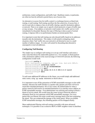
![Router Security Configuration Guide
null routes throughout a network. However, the configuration of such advanced null
routing is beyond the scope of this guide. Null routing can also be combined with
filtering to support traceback of some types of DoS attacks, as described in [24].
Additional practices for null routing are described in [15].
It is also possible to set up automatically triggered null routing in an entire network.
Setting up such a capability is beyond the scope of this guide, for a detailed look at
the topic, consult [45].
4.4.7. Unicast Reverse-Path Forwarding Verification
Most Cisco routers running IOS 12.0 and later support a routing-based filtering
feature called IP unicast reverse-path forward (Unicast RPF) verification. When this
feature is enabled on an interface, the router uses its routing tables to decide whether
to accept or drop individual packets arriving on the interface. As noted in Section 4.3,
it is good security practice to reject a packet with a spoofed source address. Unicast
reverse-path verification supports rejecting such packets, and in some cases it can
offer significant advantages over using access lists for that purpose. Unicast reverse-
path verification is not enabled by default; you must explicitly apply it to each
interface where you want verification to be done. Used correctly, and in situations
where it applies, unicast RPF verification prevents most forms of IP address
spoofing.
How Does Unicast Reverse-Path Verification Work?
All routers maintain a routing table that lets them decide how to forward packets.
Unicast reverse-path verification uses the routing table to decide whether a packet
with a particular source address is valid: if the interface on which the packet with
address A.B.C.D was received is the one that the router would use to send a packet to
A.B.C.D, then the packet is considered ‘good’, otherwise it is ‘bad’. Good packets
are forwarded normally, bad packets are discarded.
Figure 4-7 shows two packets arriving at the router Central on its ‘inside’ interface,
Eth0/1. The first packet bears a proper source address, it is from a host behind the
South router. The second packet bears a spoofed source address, it might have been
generated by a piece of malicious software secretly installed somewhere on LAN 2.
For packet 1, the router looks up its source address, 14.2.10.2, in the routing table. It
finds the interface Eth 0/1, which is the interface on which packet 1 has arrived. This
is a match, so the router forwards packet 1 normally out interface Eth 0/0. For packet
2, the router looks up its source address, 7.12.1.20, in the route table. It finds
interface Eth 0/0, which is not the interface on which packet 2 has arrived. Because
the packet has arrived on the wrong interface, it fails unicast reverse-path
verification, and the router discards the packet.
130 Version 1.1c](https://image.slidesharecdn.com/c4-040r-02-130310054952-phpapp01/85/C4-040-r-02-130-320.jpg)
![Advanced Security Services
14.1.0.0/16 Eth0/0 Eth0/1
14.1.15.250 14.2.9.250 14.2.9.0/24
Central
t 2
ke
c
Pa
Interface Eth0/0 Trash Interface Eth0/1
Packet 1
Packet 1 src=14.2.10.2
dest=10.6.5.9
Destination Gateway Interface
14.2.9.0/24 -- Eth 0/1
14.2.10.0/24 14.2.9.64 Eth 0/1 Packet 2
14.2.6.0/24 14.1.1.20 Eth 0/0 src=7.12.1.20
14.1.0.0/16 -- Eth 0/0 dest=7.12.1.20
0.0.0.0/0 14.1.1.250 Eth 0/0
Routing Table
Figure 4-7: IP Unicast RFP Verification
Because unicast RPF verification uses the route table, it automatically adjusts to most
changes in network structure. Access lists, while more broadly applicable, also
require more maintenance.
When to Avoid Unicast Reverse-Path Verification
This facility can be very useful for rejecting packets with improper IP source
addresses, but only when the network architecture permits it to be used. Avoid
unicast RPF verification if any of the following conditions apply; use access lists
instead.
• Router uses asymmetric routes –
if any of the interfaces on the router participate in asymmetric routes (one
interface for sending, and a different one for receiving), then simple
unicast RPF verification may not be used. It will incorrectly reject packets
arriving on the receive leg of the asymmetric route. Cisco has stated that
future IOS versions will perform unicast RPF correctly in these cases [11].
• Router does not support CEF –
according to the Cisco documentation, unicast reverse-path verification
depends on Cisco Express Forwarding. If your router does not or cannot
support CEF, then you cannot use unicast RPF.
Version 1.1c 131](https://image.slidesharecdn.com/c4-040r-02-130310054952-phpapp01/85/C4-040-r-02-131-320.jpg)
![Router Security Configuration Guide
Unicast RPF verification is best suited for routers that act as part of the security
boundary between two networks (e.g. a filtering router between a LAN and the
Internet). Used properly, it can provide better performance than an access list for
ingress and egress address filtering. For more details on how and where to apply
unicast RPF verification, consult [10].
Configuring Unicast Reverse-Path Verification
Unicast RPF verification depends on a particular routing mode called Cisco Express
Forwarding (CEF). Therefore, to use unicast RPF, first enable CEF, and then enable
verification on the desired interfaces. The transcript below shows how to enable
verification on the router Central.
Central# config t
Central(config)# ip cef
Central(config)# interface eth 0/0
Central(config-if)# ip verify unicast reverse-path
Central(config-if)# end
Central#
Cisco routers equipped with Versatile Interface Processors (VIPs) may require you to
enable CEF with the command ip cef distributed instead of the simple version
shown above. Consult [10] for details about CEF requirements. Note that you must
not turn off CEF while unicast RPF is enabled.
To check whether unicast RPF is enabled on a particular interface, or to view
statistics about dropped packets, use show ip interface interface-name. The
example below shows how the output will look when unicast RPF is enabled in IOS
12.3. Under 12.2 and earlier, only the lines about drops may appear.
Central# show ip interface eth0/0
Ethernet0/0 is up, line protocol is up
Internet address is 14.1.15.250/16
Broadcast address is 255.255.255.255
.
.
IP verify source reachable-via RX, allow default
0 verification drops
0 suppressed verification drops
Central#
To disable unicast RPF, enter interface configuration mode and use the command
no ip verify unicast reverse-path (12.0 through 12.2) or no ip verify
unicast (12.3 and later).
Unicast Reverse-Path Verification and Access Lists
Cisco IOS version 12.1 and later include significant enhancements to unicast RPF. In
particular, access lists may be applied to RPF. When a packet fails reverse-path
verification, then the access lists are applied. If the access list denies the packet, then
it is dropped. If the access list permits the packet, then it is forwarded. Thus, the
access list allows you to create exceptions to unicast RPF’s usual functioning. Also,
132 Version 1.1c](https://image.slidesharecdn.com/c4-040r-02-130310054952-phpapp01/85/C4-040-r-02-132-320.jpg)
![Advanced Security Services
if the access list rule that denies a packet includes the log qualifier (see Section
4.3.1) then a log message is generated.
For more information about advanced unicast RPF features, consult [11] and [15].
4.4.8. References
[1] Albritton, J., Cisco IOS Essentials, McGraw-Hill, 1999.
An excellent introduction to basic Cisco IOS tasks. Portions of this book that
are particularly relevant to Routing Protocols are Chapters 2 and 7.
[2] Parkhurst, W.R., Cisco Router OSPF - Design and Implementation Guide,
McGraw-Hill, 1998.
Comprehensive and practical guide to OSPF use. Includes discussion of
design issues, security, implementation, and deployment.
[3] Black, U., IP Routing Protocols, Prentice Hall, 2000.
A very good survey of routing protocols and the technologies behind them.
[4] Moy, J.T., OSPF – Anatomy of an Internet Routing Protocol, Addison-Wesley,
1998.
Detailed analysis of OSPF and MOSPF, with lots of practical advice, too.
Includes a good section on troubleshooting.
[5] Thomas, T.M., OSPF Network Design Solutions, Cisco Press, 1998.
This book offers a good overview of IP routing and related topics, and also
explains how to configure Cisco routers for OSPF in a variety of situations.
[6] Stevens, W.R., TCP/IP Illustrated, Volume 1, Addison-Wesley, 1994.
The most comprehensive and readable guide to the TCP/IP protocol suite;
great technical background for any network analyst.
[7] Chappell, Laura, Editor, Advanced Cisco Router Configuration, Cisco Press,
1999.
A great reference book for a variety of Cisco configuration topics, including
routing and routing protocols.
[8] Rudenko, I., Cisco Routers for IP Routing: Little Black Book, Coriolis Group,
1999.
A very practical and pragmatic guide to setting up routing protocols.
Version 1.1c 133](https://image.slidesharecdn.com/c4-040r-02-130310054952-phpapp01/85/C4-040-r-02-133-320.jpg)
![Router Security Configuration Guide
[9] Cisco Systems, “RIP and OSPF Redistribution”, Cisco Internetworking Case
Studies, Cisco Systems, 2000.
available under
http://www.cisco.com/univercd/cc/td/doc/cisintwk/ics/
[10] “Configuring Unicast Reverse Path Forwarding”, Cisco IOS 12.0 Security
Configuration Guide, Cisco Systems, 2000.
available at: http://www.cisco.com/univercd/cc/td/doc/product/
software/ios120/12cgcr/secur_c/scprt6/scrpf.pdf
Basic IOS documentation on unicast reverse-path forwarding verification,
includes a good explanation of the concepts.
[11] “Unicast Reverse Path Forwarding Enhancements”, Cisco IOS 12.1(2)T Release
Notes, Cisco Systems, 2000.
available at: http://www.cisco.com/univercd/cc/td/doc/product/
software/ios121/121newft/121t/121t2/rpf_plus.htm
Documentation for new Unicast RPF features that are being integrated into
IOS 12.1 releases.
[12] Plummer, D., “An Ethernet Address Resolution Protocol of Converting Network
Protocol Addresses to 48-bit Ethernet Address for Transmission on Ethernet
Hardware”, RFC 826, 1982.
The IETF specification for ARP.
[13] Smoot, C-M. and Quarterman, J., “Using ARP to Implement Transparent Subnet
Gateways”, RFC 1027, 1987.
The IETF specification for Proxy ARP.
[14] Rybaczyk, P., Cisco Router Troubleshooting Handbook, M&T Books, 2000.
This pragmatic volume offers good advice for diagnosing and correcting
problems with routing and routing protocols.
[15] Greene, B. and Smith, P., Cisco ISP Essentials, 1st Edition, Cisco Press, April
2002.
This detailed Cisco guide for Internet Service Providers includes extensive
discussion of routing protocols (especially BGP), and an in-depth treatment
of Unicast RPF, all with fully worked-out examples.
[16] “Routing Basics”, Cisco Internetworking Technology Overview, Cisco Systems,
2002.
available at: http://www.cisco.com/univercd/cc/td/doc/cisintwk/
ito_doc/routing.htm
As a general overview of routing concepts and terminology, this document
gives a broad, performance-oriented view of IP routing.
134 Version 1.1c](https://image.slidesharecdn.com/c4-040r-02-130310054952-phpapp01/85/C4-040-r-02-134-320.jpg)
![Advanced Security Services
[17] Stewart, J.W., BGP4 - Inter-Domain Routing in the Internet, Addison-Wesley,
1999.
Provides a good overview of BGP and practical advice on using it.
[18] Thomas, R., “Secure BGP Template Version 4.1”, October 2005.
available at: http://www.cymru.com/Documents/secure-bgp-template.html
This short but highly prescriptive document gives a detailed example of a
locked-down configuration for a backbone or border router using BGP-4.
[19] Doyle, J. Routing TCP/IP - Volume 1, Cisco Press, 1998.
Provides a basic understanding of routers and routing protocols through a
thorough inspection of IP interior gateway routing protocols. The
bookemphasizes techniques for designing efficient networks, an excellent
reference for network engineers responsible for enterprise design.
[20] “Enhanced IGRP”, Cisco Internetworking Technology Overview, Cisco
Systems, 2002.
A white paper that describes the features and operation of EIGRP.
[21] Parkhurst, W.R., Cisco BGP-4 Command and Configuration Handbook, Cisco
Press, 2001.
A clear, concise resource for Cisco IOS software BGP-4 commands. The
command guide provides very good configuration, troubleshooting and
verification guidance.
[22] Cisco IOS IP Configuration Guide, IOS 12.2, Cisco Press, 2002.
This volume of the Cisco IOS documentation offers extensive information on
configuring all of the routing protocols discussed in this section.
[23] Panigl, Schmitz, Smith, and Vistoli, “RIPE Routing Working Group
Recommendations for Coordinated Route-flap Damping Parameters”, Version
2.0, RIPE-229, RIPE, 2001.
available at: http://www.ripe.net/ripe/docs/ripe-229.html
This note describes rationale for BGP route flap dampening, and includes
links to examples for Cisco IOS.
[24] Morrow, C., “BlackHole Route Server and Tracking Traffic on an IP Network”,
October 2001.
available at: http://www.secsup.org/Tracking/
This terse and technical note describes a technique for using null routing,
BGP, and access control lists to trace back the sources of some DoS attacks.
Version 1.1c 135](https://image.slidesharecdn.com/c4-040r-02-130310054952-phpapp01/85/C4-040-r-02-135-320.jpg)
![Router Security Configuration Guide
[25] “IP Routing Protocol Groups”, Cisco Technologies Documentation, Cisco
Systems. available under: http://www.cisco.com/en/US/tech/tk365/
tsd_technology_support_protocol_home.html
This page offers access to a large number of technical documents and
examples about IOS-supported routing protocols, organized by protocol.
[26] “IS-IS HMAC-MD5 Authentication and Enhanced Clear Text Authentication”
IOS Release Notes for 12.0(21)ST and 12.0(22)S, Cisco Systems, 2001.
Good reference describing the IOS command set for HMAC-MD5
authentication.
[27] Martey, A., IS-IS Network Design Solutions, Cisco Press, 2002.
The definitive IS-IS reference and design guide.
[28] “Configuring IS-IS Authentication”, Cisco Technology White Paper, Cisco
Systems, 2003.
available at: http://www.cisco.com/warp/public/97/isis_authent.pdf
Provides a good overview of IS-IS authentication with an emphasis on
plaintext authentication.
[29] Shamin, F., Troubleshooting IP Routing Protocols, Cisco Press, 2002.
A comprehensive hands-on guide for resolving IP routing problems.
[30] Halabi, S., Internet Routing Architectures - Second Edition, Cisco Press, 2001.
A thorough presentation of inter-domain routing concepts, issues, and
scenarios.
[31] Zhang, R. and Bartell, M., BGP Design and Implementation, Cisco Press, 2004.
A discussion of advanced BGP topics applicable to both enterprises and
ISPs, including guidance on multiprotocol extensions.
[32] Gill, Heasley, and Meyer, “The Generalized TTL Security Mechanism
(GTSM),” RFC 3682, February 2004.
The IETF specification for GTSM.
[33] “BGP Support for TTL Security Check”, Cisco IOS Release Notes for
12.0(27)S, 12.3(7)T, and 12.2(25)S, Cisco Systems, 2003.
A reference for IOS configuration of the GTSM, containing command syntax
and a detailed configuration procedure.
[34] Heffernan, A., “Protection of BGP Sessions via the TCP MD5 Signature
Option,” RFC 2385, August 1998.
136 Version 1.1c](https://image.slidesharecdn.com/c4-040r-02-130310054952-phpapp01/85/C4-040-r-02-136-320.jpg)
![Advanced Security Services
The IETF specification for MD5 protection of BGP sessions.
[35] Greene, B., ISP Security Boot Camp, Cisco course notes, Cisco Systems, 2002.
available at: ftp://ftp-eng.cisco.com/cons/isp/security/
Ingress-Prefix-Filter-Templates/Prefix-List-Filtering-Mar-03.pdf
A good overview of prefix filtering with examples and references.
[36] Bush, Griffin, and Mao, “Route Flap Damping: Harmful?” NANOG
presentation, 2002.
available at: http://www.nanog.org/mtg-0210/ppt/flap.pdf
A conference presentation that questions the value of route flap damping.
[37] Smith, P., “Flap Damping - Where to now?,” Proceedings of the RIPE50
Conference, 2005.
available at: http://www.ripe.net/ripe/meetings/ripe-50/
presentations/ripe50-plenary-wed-flap-damping.pdf
A presentation of flap damping issues and a call for a response to deal with
those issues.
[38] “The Team Cymru Bogon Reference Page”, Team Cymru, 2005.
available at: http://www.cymru.com/Bogons/
An excellent resource about bogons and bogon filtering. This page also
provides a well-maintained list of bogon address ranges in a variety of
formats.
[39] “ARIN 2005 Statistics”, ARIN, 2005.
available at: http://www.arin.net/statistics/index.html#cidr
An overview of address space allocated by ARIN, with links to detailed lists
and historical data.
[40] Vegoda, L., “Address Space Managed by the RIPE NCC”, RIPE 349, RIPE,
2005.
available at: http://www.ripe.net/ripe/docs/
ripe-ncc-managed-address-space.html
A list of minimum practical allocations by RIPE, for use in prefix list
filtering. Also includes some explanatory notes.
[41] “Allocation sizes within APNIC Address Ranges”, Asia Pacific Network
Information Center, 2005.
available at: http://www.apnic.net/db/min-alloc.html
A list of minimum practical allocations by APNIC, for use in prefix list
filtering.
Version 1.1c 137](https://image.slidesharecdn.com/c4-040r-02-130310054952-phpapp01/85/C4-040-r-02-137-320.jpg)
![Router Security Configuration Guide
[42] Greene, B., “Ingress Prefix Filter Templates”, version 1.4, Cisco Systems, July
2005.
available under: ftp://ftp-eng.cisco.com/cons/isp/security/
Ingress-Prefix-Filter-Templates/
IOS command templates for ingress prefix filter lists, to be used for filtering
martians. Maintained as part of the bogon project [38].
[43] Karrenberg, D., Moskowitz, B. and Rekhter, Y. “Address Allocation for Private
Internets”, RFC 1918, February 1996.
This RFC describes the reserved IP address allocations for private intranets.
[44] “SAFE: Best Practices for Securing Routing Protocols”, Cisco white paper,
Cisco Systems, 2004.
available at: http://www.cisco.com/warp/public/cc/so/neso/vpn/
prodlit/sfblp_wp.pdf
A recent and detailed paper about threats to routing protocols and means to
mitigate those threats.
[45] “Remotely Triggered Black Hole Filtering – Destination Based and Source
Based”, Cisco white paper, Cisco Systems, 2005.
available at: http://www.cisco.com/warp/public/732/Tech/security/
docs/blackhole.pdf
An in-depth description of how to set up centrally-triggered null routing
using your internal BGP mesh.
138 Version 1.1c](https://image.slidesharecdn.com/c4-040r-02-130310054952-phpapp01/85/C4-040-r-02-138-320.jpg)
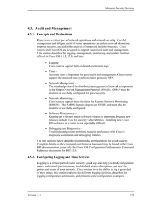
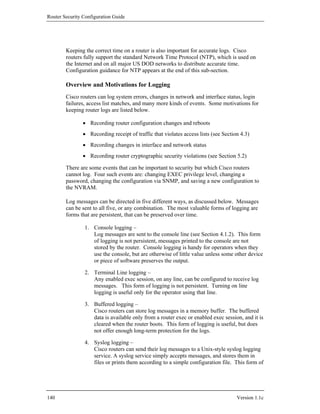
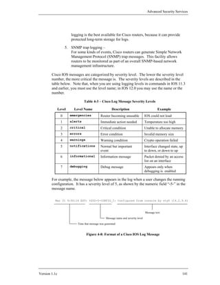
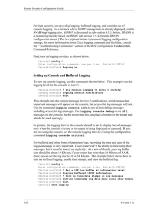
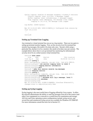
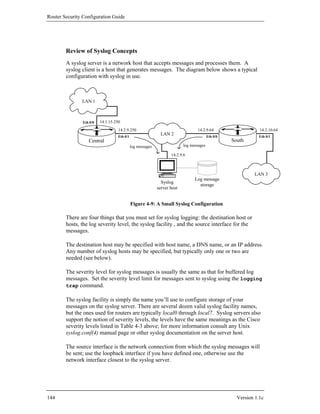
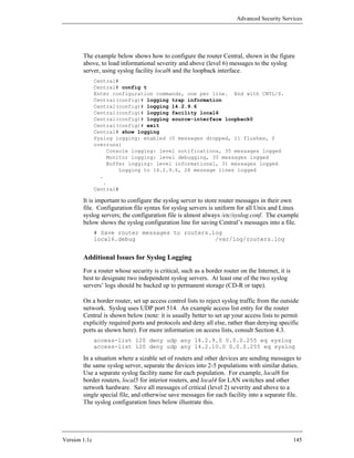
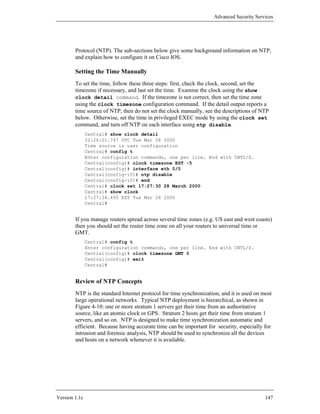
![Router Security Configuration Guide
Atomic Clock
Stratum 1
Stratum 2
Stratum 3
Stratum 4
Figure 4-10: The NTP Hierarchy
If an NTP client is configured with several NTP servers, it will select among them
automatically based on time accuracy and stratum level. Cisco routers (except the
old 1000-series) are capable of acting at any stratum in the NTP hierarchy except
stratum 1. As shown in the figure, NTP clients may also have peer associations;
setting up peer associations is beyond the scope of this guide. For more information
about NTP configuration, consult the “Performing Basic System Management”
chapter of the Cisco IOS Configuration Fundamentals Configuration Guide.
In some cases, a Cisco router may be used as the border router between the Internet
and an internal, protected network which requires time synchronization from a time
server on the Internet. In these cases, the router should be configured as an NTP
client to two or more reliable Internet time servers, and may serve as the NTP server
to the hosts on the internal network. This configuration will allow the router to block
general NTP traffic at the boundary. If at all possible, NTP authentication should
also be used (see below).
Commercial stratum 1 radio receivers are available that use a broadcast time source
(e.g. GPS or a time signal from the US Naval Observatory) to offer NTP service. If
your network has one of these, then you can configure all your routers to get their
time from it, directly or indirectly. For more information on this topic, see [11].
For more information about NTP and Internet NTP servers, or to obtain the latest
NTP server software and tools for a variety of operating systems, visit the main NTP
site: http://www.ntp.org/. Note that Cisco IOS implements version 3 of the
NTP protocol, and can be monitored using NTP standard-compliant tools, such as the
ntpq tool distributed with the open-source NTP package.
148 Version 1.1c](https://image.slidesharecdn.com/c4-040r-02-130310054952-phpapp01/85/C4-040-r-02-148-320.jpg)
![Advanced Security Services
! turn on timestamps for log entries
service timestamps log datetime msec localtime show-timezone
! setting logging levels and syslog parameters
logging console notifications
logging monitor debug
logging buffered 16000 informational
logging facility local6
logging source-interface loopback0
logging 14.2.9.6
logging on
! a tiny access list to permit access only for Central
access-list 21 permit 14.2.9.250
access-list 21 deny any
! designate Central as our sole NTP server with authentication
ntp authentication-key 1 md5 LTGTR-769015
ntp authenticate
ntp trusted-key 1
ntp access-group peer 21
ntp server 14.2.9.250 key 1 source loopback0
4.5.3. Security for the Simple Network Management Protocol (SNMP)
The Simple Network Management Protocol (SNMP) supports a connection between
two entities that communicate with each other: the manager and the managed entity,
the agent. In the case of Cisco routers, the router is always the agent. A software
application on a PC or workstation normally acts as the manager. A free and usable
implementation of an SNMP agent and manager may be obtained from the NET-
SNMP home page (http://net-snmp.sourceforge.net/ - NET-SNMP is the
successor to ucd-snmp, the SNMPv3 agent used in the creation of this section).
An SNMP agent device maintains information and makes it accessible to managers;
the information on each device is organized in a virtual store called a Management
Information Base (MIB). SNMP is the transport protocol used to share and change
information between MIBs.
A MIB is a hierarchical, tree-like structure used to store a virtual database of network
management information. Each piece of data, or object, in a MIB is referenced by an
object identifier (OID). An OID is a unique, dotted, numerical name, where the dots
separate branches in a MIB tree. When requesting the value of an object, one may use
the OID or the actual name of each branch (separated by dots). If the referenced
value is not a bottom leaf of the tree, values for the entire branch are returned. An in
depth discussion of SNMP data organization is outside the scope of this guide; for
more information consult [7].
SNMP may be used to query the status of or set the values of network components.
SNMP may also be used by an entity on the network to send alerts indicating
Version 1.1c 151](https://image.slidesharecdn.com/c4-040r-02-130310054952-phpapp01/85/C4-040-r-02-151-320.jpg)
![Router Security Configuration Guide
problems. There are currently three versions of SNMP: SNMPv1, SNMPv2c and
SNMPv3. IOS version 11.3 supports SNMPv1 and SNMPv2c. IOS versions 12.0
and later support all three versions of SNMP.
This section will give a brief overview of SNMP security and will detail how to
enable SNMP more securely. Cisco IOS supports a large number of SNMP-related
commands, those that do not have a direct impact on security are not covered.
SNMP Security
When SNMPv1 was developed, it was originally intended to be a short-term solution
for (remotely) managing networks. As such, it was developed quickly and strong
security was not a requirement. However, since it was the only network management
protocol available at the time, it became widely used. Proposals were put forth to
integrate security (as well as more functionality) into later versions of the protocol.
Unfortunately, conflict arose between competing proposal advocates and no security
standard was agreed upon. Consequently strong security was left out of SNMPv2c. In
the late 1990s, SNMPv3 was developed specifically with strong security in mind.
SNMPv1 and SNMPv2c have weak security. SNMPv1 uses a community string to
limit access to the MIB. This string is sent across the network in clear text. SNMPv2
relies on the same mechanism for access control to the MIB. SNMPv3 defines three
levels of security. They are described in the table below.
Table 4-4: SNMPv3 Security
Security Level Authentication Encryption
SNMPv3 noAuthNoPriv Username sent in the clear None
authNoPriv HMAC-MD5 or HMAC-SHA None
authPriv HMAC-MD5 or HMAC-SHA DES (56-bit)
The Cisco documentation indicates that IOS 12.0 supports all three security levels.
However, DES 56-bit encryption was not supported in the versions of IOS used for
preparation of this section (12.0(7) and 12.0(5)).
SNMP Vulnerability
In early 2002, serious SNMP vulnerabilities were disclosed that affected Cisco
routers and many other network devices. If your IOS release is one of the vulnerable
ones (and virtually every IOS prior to February 2002 is) then you should either
upgrade your IOS (recommended), disable SNMP altogether, or take other protective
measures. For more information, consult the Cisco security advisory “Malformed
SNMP Message-Handling Vulnerabilities” [9].
152 Version 1.1c](https://image.slidesharecdn.com/c4-040r-02-130310054952-phpapp01/85/C4-040-r-02-152-320.jpg)
![Advanced Security Services
and the falling thresholds of an alarm are dependent on the previous configuration of
an associated event. The basic IOS RMON agent supports the following commands:
show rmon alarms Display information on alarms configured
show rmon events Display information on events configured
rmon event number [log] Configure an RMON event
[trap community]
[description string]
[owner string]
rmon alarm number MIB-object Configure an RMON alarm
interval {delta | absolute}
rising-threshold value [event-number]
falling-threshold value [event-number] [owner string]
The first two commands display information on configured RMON facilities. Use
the rmon event command to provide a description of an event and specifies
whether a message is logged or a trap is generated. Use the rmon alarm command
to designate the actual MIB variable monitored on the Cisco router. RMON alarms
provide an excellent tool for monitoring the network interfaces supported by the
router. However, there are several limitations on the type of SNMP variables RMON
is capable of monitoring. Alarms may define any SNMP MIB variable that has an
elementary data type such as integer, counter, gauge, timeticks, etc. The MIB object
monitored must also resolve to an ASN.1 notation. It is acceptable to use the Object
Identifier (OID) or the qualified variable name that resolves to its OID. An important
requirement that is easily overlooked is the instance number of the monitored
variable. All monitored objects must include an instance number of the monitored
variable. Variables included in the SNMP table format will have an instance number
equivalent to the entry number of the table. All other elementary data variables
should have an instance number of ‘0’. For example, the following command defines
an alarm configured on a member of the MIB II interfaces table, ifTable:
Central# config t
Enter configuration commands, one per line. End with CNTL/Z.
Central(config)# rmon alarm 1 ifEntry.13.1 30 delta
rising-threshold 40 1 falling-threshold 0 owner rscg
Central(config)# exit
Central# show rmon alarms
Alarm 1 is active, owned by rscg
Monitors ifEntry.13.1 every 30 second(s)
Taking delta samples, last value was 3
Rising threshold is 40, assigned to event 1
Falling threshold is 0, assigned to event 0
On startup enable rising or falling alarm
Alarm 2 is active, owned by config
.
.
Central#
Version 1.1c 157](https://image.slidesharecdn.com/c4-040r-02-130310054952-phpapp01/85/C4-040-r-02-157-320.jpg)
![Router Security Configuration Guide
selected. After downloading the IOS binary file, check the length against the printed
page. The summary page will also include the MD5 hash value for the IOS image;
use the md5sum command, or a similar checksum utility, to check the hash value. If
the length or hash of your file differ from the summary page, discard the file and
download it again.
Before You Perform the Update
Check all the items below before installing a new IOS image on your router.
1. Ensure that you have enough memory.
Cisco routers have two fundamental kinds of memory: RAM and Flash.
Every Cisco IOS release has minimum memory requirements. Use the
commands show version and show flash to check the amount of
memory your router has. Do not install an update unless the router to be
upgraded satisfies the memory requirements for both RAM and Flash.
(Often, a major upgrade will require more memory, because many Cisco
routers are configured with just enough memory to run the IOS version
pre-installed at the time of purchase. When possible, it is prudent to
configure operational routers with as much memory as they can hold.)
2. Check your TFTP, RCP, or FTP configuration.
Router software updates are usually performed using TFTP or FTP;
Cisco IOS 12.0 supports FTP, most earlier releases do not. Make sure
that the TFTP or FTP server is correctly set up for both upload and
download. Copy the new Cisco IOS software into the server’s download
directory. Most newer IOS releases support SCP, a secure file copy
protocol based on SSH.
If possible, use SCP or FTP for performing Cisco upgrades. (If the
router to be upgraded is running IOS 11.3 or earlier, then FTP will
probably not be available.) While TFTP is supported by all IOS
versions, it is not a secure service, and should not be running in a secure
network. Enable TFTP only for the update sequence, then disable it
again.
To use SCP, you will need to have an SSH server running on a host in
your network. For more information, consult [12].
3. Schedule your downtime.
Installing an update imposes a minimum downtime, and may impose
much longer downtime (up to half an hour if things go wrong and you
have to back out). Schedule your upgrade ahead of time, and inform the
user community as needed.
4. Read the entire upgrade procedure, below.
Review the entire procedure before you start. Be sure that you are
familiar with all the IOS commands involved.
160 Version 1.1c](https://image.slidesharecdn.com/c4-040r-02-130310054952-phpapp01/85/C4-040-r-02-160-320.jpg)
![Router Security Configuration Guide
3. Back up the current running configuration.
Copy your current startup configuration to your TFTP or FTP server
using the copy command as shown below.
Central# copy startup-config tftp:
or
Central# copy startup-config ftp:
You must supply the IP address or host name of the server host. If this
step fails, do not proceed, abandon the update and check your server
configuration before trying again.
4. Load the new software.
Copy the new IOS software from the TFTP or FTP server to the flash
memory of the router. On some Cisco routers, the flash will be erased
automatically during this step; if asked whether to erase the flash, answer
yes. Use the copy command as follows.
Central# copy tftp: flash:
or
Central# copy ftp: flash:
On some Cisco routers, it is possible to store several IOS releases in flash
memory and select which one to run. (If you have several IOS images in
flash, you can specify which one to use at boot using the boot system
command.) If this copy succeeds, your router may automatically reboot;
if it does not, then reboot it manually using the command reload. If you
are performing the update over a network connection, your connection
will be broken at this point.
Central# reload
Proceed with reload? [confirm] y
5. Confirm the new IOS version and boot image.
Watch the boot messages on the router console to confirm the new IOS
software version and boot image. If you performed steps 1 through 4
over a network connection, re-establish the connection at this point and
check the IOS version and boot image with show version. Then,
enable privileges and confirm the configuration status with show
running-config. Check the status of the interfaces, and check that the
access lists and static routes are still present.
Central# show version
Cisco Internetwork Operating System Software
IOS(tm) 1600 Software (C1600-SY56I-M), Version
12.0(9), RELEASE SOFTWARE
. . .
Central# show ip interface
. . .
Central# show running-config
. . .
Central#
162 Version 1.1c](https://image.slidesharecdn.com/c4-040r-02-130310054952-phpapp01/85/C4-040-r-02-162-320.jpg)
![Advanced Security Services
6. Bring up external interfaces, if necessary.
If you shut down your router’s external interfaces in step 2, they should
have come back up as part of the reload in step 4. If the second
command in step 5 showed that they did not come back up, then bring
them back up now using the command no shutdown.
Central# config t
Central(config)# interface eth 0/0
Central(config)# no shutdown
Central(config)# end
Depending on network speed and router model, this procedure may take about 5-20
minutes. Note that, for some older Cisco router models, additional hardware-specific
steps may be needed. Consult the release notes for the particular router for details.
Transcript of a Successful Update Procedure
The recorded transcript below shows an upgrade of a Cisco 3640 router from IOS
11.3(4) to 12.0(5).
South> show version
Cisco Internetwork Operating System Software
IOS(tm) 3600 Software (C3640-I-M), Version 11.3(4)T1, RELEASE SOFTWARE (fc1)
.
.
South>show flash
System flash directory:
File Length Name/status
1 3208548 c3640-i-mz.113-4.T1
[3208612 bytes used, 5179996 available, 8388608 total]
8192K bytes of processor board System flash (Read/Write)
South> enable
Password:
South# copy flash: tftp
System flash directory:
File Length Name/status
1 3208548 c3640-i-mz.113-4.T1
[3208612 bytes used, 5179996 available, 8388608 total]
Address or name of remote host [14.2.9.6]? 14.2.9.6
Source file name? c3640-i-mz.113-4.T1
Destination file name [c3640-i-mz.113-4.T1]? c3640-i-mz-113-4.T1.bak
Verifying checksum for 'c3640-i-mz.113-4.T1' (file # 1)... OK
Copy 'c3640-i-mz.113-4.T1' from Flash to server
as 'c3640-i-mz-113-4.T1.bak'? [yes/no]yes
!!!!!!!!!!!!!!!!!!!!!!!!!!!!!!!!!!!!!!!!!!!!!!!!!!!!!!!!!!!!!!!!!!!!!!!!
Upload to server done
Flash device copy took 00:00:19 [hh:mm:ss]
South# config t
Enter configuration commands, one per line. End with CNTL/Z.
South(config)# interface ethernet0/1
South(config-if)# shutdown
South(config-if)# exit
South(config)# exit
South#
Version 1.1c 163](https://image.slidesharecdn.com/c4-040r-02-130310054952-phpapp01/85/C4-040-r-02-163-320.jpg)
![Router Security Configuration Guide
South# copy running-config tftp
Remote host []? 14.2.9.6
Name of configuration file to write [south-confg]? south-config.bak
Write file south-config.bak on host 14.2.9.6? [confirm]
Building configuration...
Writing south-config.bak !! [OK]
South# copy tftp flash
System flash directory:
File Length Name/status
1 3208548 c3640-i-mz.113-4.T1
[3208612 bytes used, 5179996 available, 8388608 total]
Address or name of remote host [255.255.255.255]? 14.2.9.6
Source file name? c3640-ik2o3s-mz_120-5_T1.bin
Destination file name [c3640-ik2o3s-mz_120-5_T1.bin]? c3640-ik2o3s-mz_120-
5_T1.bin
Accessing file 'c3640-ik2o3s-mz_120-5_T1.bin' on 14.2.9.6...
Loading c3640-ik2o3s-mz_120-5_T1.bin from 14.2.9.6 (via Ethernet0/0): !
[OK]
Erase flash device before writing? [confirm]
Flash contains files. Are you sure you want to erase? [confirm]
Copy 'c3640-ik2o3s-mz_120-5_T1.bin' from server
as 'c3640-ik2o3s-mz_120-5_T1.bin' into Flash WITH erase? [yes/no]yes
Erasing device... eeeeeeeeeeeeeeeeeeeeeeeeeeeeeeee ...erased
Loading c3640-ik2o3s-mz_120-5_T1.bin from 14.2.9.6 (via Ethernet0/0):
!!!!!!!!!!!
!!!!!!!!!!!!!!!!!!!!!!!!!!!!!!!!!!!!!!!!!!!!!!!!!!!!!!!!!!!!!!!!!!!!
[OK - 7656076/8388608 bytes]
Verifying checksum... OK (0xDC3B)
Flash device copy took 00:00:50 [hh:mm:ss]
South# reload
System configuration has been modified. Save? [yes/no]: no
Proceed with reload? [confirm] y
%SYS-5-RELOAD: Reload requested
System Bootstrap, Version 11.1(19)AA, EARLY DEPLOYMENT SOFTWARE (fc1)
Copyright (c) 1998 by cisco Systems, Inc.
C3600 processor with 32768 Kbytes of main memory
Main memory is configured to 64 bit mode with parity disabled
program load complete, entry point: 0x80008000, size: 0x74d170
Self decompressing the image :
############################################# [OK]
.
.
South>
South> show ip interface brief
Interface IP-Address OK? Method Status Protocol
Ethernet0/0 14.2.9.64 YES NVRAM up up
Ethernet0/1 14.2.10.250 YES NVRAM up up
Ethernet0/2 unassigned YES NVRAM administratively down down
Ethernet0/3 unassigned YES NVRAM administratively down down
South> enable
Password:
South# show running-config
Building configuration...
164 Version 1.1c](https://image.slidesharecdn.com/c4-040r-02-130310054952-phpapp01/85/C4-040-r-02-164-320.jpg)
![Router Security Configuration Guide
4.5.6. Diagnosing and Debugging Router Operation
Effective logging and SNMP help an administrator to stay aware of their routers’
status and operational condition. When a problem occurs, or when a network is
under attack, Cisco IOS diagnostic and debug facilities can be used to get vital
information, identify sources and causes, and validate repairs.
Techniques for troubleshooting and debugging routers could (and do) fill entire
books. This short sub-section describes some of the most useful techniques for IOS
11.3 and later. The techniques fall into three groups:
• Router status and configuration commands –
These commands display information about the settings and tables held by
the router; some of this information is global to the whole router, and some
is particular to each interface.
• Router throughput and traffic commands –
Each interface, and some other facilities, keep input/output statistics.
There are IOS commands to display these statistics that can be used to
detect problems.
• Debugging commands –
Virtually every IOS facility and protocol has associated debugging
commands, and they offer a great deal of visibility into the operation of the
router. These commands typically produce a correspondingly great deal of
output, so use them sparingly.
These commands can also be used to help verify that security measures are in force.
Testing and validation are covered in Section 6.
Router Status and Configuration Commands
Each of the items below describes a single status query. There are literally hundreds
of such queries available, even on the simplest Cisco routers, for a discussion of
some other useful ones, see [2] and [7]. The ones listed here are commonly used for
simple troubleshooting, and are useful for understanding a Cisco router’s disposition
in a typical TCP/IP network.
1. Viewing the current log –
To view the current buffered log messages, use the command show
logging. The output consists of two parts: a summary of the current
logging configuration, and the log messages. The messages are shown in
the order they occurred, so recent messages are at the end of the listing.
The buffered log messages are cleared when the router reboots, so the
first few messages put into the log reflect startup activity. In the example
below, an unauthorized attempt to telnet to the router itself has been
logged by access list 131. For more discussion of logging, consult
Section 4.5.2.
East# show logging
166 Version 1.1c](https://image.slidesharecdn.com/c4-040r-02-130310054952-phpapp01/85/C4-040-r-02-166-320.jpg)
![Advanced Security Services
Syslog logging: enabled (0 messages dropped, 0 flushes)
Console logging: level debugging, 56 message lines logged
Monitor logging: level debugging, 32 message lines logged
Buffer logging: level debugging, 56 message lines logged
Trap logging: level informational, 33 message lines logged
Logging to 14.2.9.6, 33 message lines logged
Log Buffer (16000 bytes):
00:00:17: %LINK-3-UPDOWN: Interface Ethernet0, changed
state to up
.
.
Mar 3 12:51:52 EST: %SEC-6-IPACCESSLOGP: list 131 denied
tcp 172.17.101.250(47746) -> 0.0.0.0(23), 1 packet
East#
Note: log messages should always include the time of the event. In a
router using NTP, the first few log messages will include the time since
boot instead of the correct time, because the messages are generated
before NTP has synchronized.
2. Viewing the current route table –
To view the current route table, use the command show ip route.
Depending on the size of the network and the kinds of routing protocols
used, this list may be very large. A very important part of reviewing the
route table is checking the route codes and checking the destination
gateway. Each route code identifies how one route joined the table; the
destination gateway is simply the next hop on that route. Check the route
codes to make sure that all the routes joined the table either directly
(code C), or were added as static routes (code S), or were added by a
configured routing protocol (codes R, O, and others, see Section 4.4).
Figure 4-11 shows how to interpret the output of show ip route.
Note that the route table listing on an operational router will often be
much longer than this sample.
Gateway of last resort is 14.1.1.250 to network 0.0.0.0
O IA 7.0.0.0/8 [110/12] via 14.1.1.250, 2d18h, Ethernet0/0
O IA 7.0.0.0/8 [110/14] via 14.1.1.250, 2d18h, Ethernet0/0
O 172.18.0.0/16 [110/11] via 14.1.1.250, 1d13h, Ethernet0/0
C 14.1.0.0/16 is directly connected, Ethernet0/0
O E2 14.2.6.0 [110/10] via 14.1.1.20, 1d01h, Ethernet0/0
C 14.2.9.0 is directly connected, Ethernet0/1
R 14.2.10.0 [120/1] via 14.2.9.64, 00:01:05, Ethernet0/1
O*E2 0.0.0.0/0 [110/3] via 14.1.1.250, 2d19h, Ethernet 0/0
Route codes Destination
gateways
Figure 4-11: Interpreting a Route Table Listing
Version 1.1c 167](https://image.slidesharecdn.com/c4-040r-02-130310054952-phpapp01/85/C4-040-r-02-167-320.jpg)
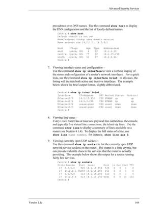
![Router Security Configuration Guide
The first line is the RIP route protocol service (local port 520). The
second line is the SNMP service to a host running an SNMP/RMON
management tool (local port 161). The third line is the network time
service (NTP, port 123). The fourth line is the logging client, sending
syslog messages to a Unix host (remote port 514).
10. Viewing the current configuration –
To view the current running IOS configuration, use the command show
running. The resulting output will typically be fairly long. To review a
configuration in depth, save the command results to a file, print it, and
review the hardcopy. To view the saved startup configuration (in
NVRAM) use show startup. Normally, these two configurations
should be very similar. If the configurations are very large and complex,
use a file comparison tool, such as Unix diff or Windows fc, to highlight
the differences.
Archive a copy of the configuration after any major change, or on a
monthly basis. This can help with problems, and also shorten downtime
if the router loses its stored configuration. The example below shows
how to save an archive copy of a configuration to an FTP server, using
IOS 12.0.
Central# config t
Enter configuration commands, one per line. End with
CNTL/Z.
Central(config)# ip ftp password 0 r0ut3rQQ
Central(config)# ip ftp user rscg
Central(config)# exit
Central# copy running-config ftp
Address or name of remote host []? 14.2.9.1
Destination filename [central-confg]? central-config.txt
Writing central-config.txt !!
5699 bytes copied in 12.716 secs (474 bytes/sec)
Central#
In IOS 11.3 and earlier, FTP is not supported, but TFTP can be used for
making archive copies in a very similar manner (see Section 4.5.5).
Because TFTP is insecure, it should be used with care and disabled when
not in use. Another way to get an archive copy of the running
configuration is to use text logging features of Telnet and terminal
emulation applications.
11. Viewing currently running processes –
Many IOS services and facilities run as separate IOS processes. Use the
command show process to list the running processes. The output is
usually quite long. Check for unwanted processes and services.
170 Version 1.1c](https://image.slidesharecdn.com/c4-040r-02-130310054952-phpapp01/85/C4-040-r-02-170-320.jpg)
![Advanced Security Services
Router Throughput and Traffic Commands
The commands listed below display various traffic statistics that can be useful in
diagnosing router traffic flow. There are hundreds of traffic and processing status
commands in Cisco IOS, see [7] for more information about some of them.
Understanding normal network and link traffic loads can be critical for identifying
anomalous conditions that are indications of attacks, misconfiguration, or component
failure. Most of these commands produce voluminous but clearly formatted output.
1. Viewing the network traffic on a per-interface basis –
To view the total traffic for each interface, use the command show
interface. This will display a comprehensive report on the traffic
through all the interfaces. To view the traffic for a single interface,
simply supply that interface name to the command. The example below
shows the output format for a single Ethernet interface.
Central# show interface eth 0/0
Ethernet0/0 is up, line protocol is up
Hardware is AmdP2, address is 0050.7357.cbe0
Internet address is 14.1.15.250/24
. . .
Last clearing of "show interface" counters 23:20:53
. . .
991606 packets input, 103806395 bytes, 0 no buffer
Received 800624 broadcasts,0 runts,0 giants,0 throttles
0 input errors, 0 CRC, 0 frame, 0 overrun, 0 ignored
0 input packets with dribble condition detected
480919 packets output, 38371898 bytes, 0 underruns
0 output errors, 78 collisions, 1 interface resets
0 babbles, 0 late collision, 215 deferred
0 lost carrier, 0 no carrier
0 output buffer failures, 0 output buffers swapped out
Central#
If traffic volume monitoring is important for a particular interface, then
clear the counters on a periodic basis. Clearing the counters sets the
traffic volume record back to zero for both input and output. The
example below shows how to clear the counters for a single interface.
Central# clear counter Eth 0/0
Clear "show interface" counters on this interface
[confirm]y
Central#
2. Viewing IP Protocol Statistics –
To display a long listing of IP and related protocol traffic statistics, use
the command show ip traffic. The output is quite long, but can
reveal certain classes of attacks.
3. Viewing SNMP Protocol Statistics –
To display the SNMP messages statistics and configuration, use the very
Version 1.1c 171](https://image.slidesharecdn.com/c4-040r-02-130310054952-phpapp01/85/C4-040-r-02-171-320.jpg)
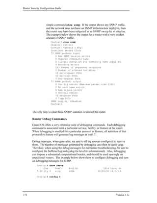
![Advanced Security Services
Enter configuration commands, one per line. End with CNTL/Z.
Central(config)# logging console information
Central(config)# logging monitor debug
Central(config)# logging buffered information
Central(config)# logging trap information
Central(config)# exit
Central#
Mar 3 17:01:58.159 EST: %SYS-5-CONFIG_I: Configured from console by
rscg on vty0 (14.2.9.6)
Central# terminal monitor
Central# debug ip icmp
ICMP packet debugging is on
Central# ! At this point, “ping central” was performed on 14.2.9.6
Mar 3 17:02:13 EST: ICMP: echo reply sent, src 14.2.9.250, dst
14.2.9.6
Central# no debug ip icmp
ICMP packet debugging is off
Central#
The Cisco documentation set includes a volume with comprehensive information
about the debug facilities and their behavior, the Cisco IOS Debug Command
Reference.
4.5.7. References
[1] Albritton, J. Cisco IOS Essentials, McGraw-Hill, 1999.
An excellent introduction to basic IOS operations, including examining the
configuration and operation of a Cisco router.
[2] Cisco IOS 12.0 Configuration Fundamentals, Cisco Press, 1999.
The sections on “Performing Basic System Management” and “Monitoring
the Router and Network” include valuable advice on how to configure basic
features and services. The section on “File Management” provides extensive
information on downloading updates.
[3] Ballew, S.M., Managing IP Networks with Cisco Routers, O’Reilly Associates,
1997.
A practical introduction to the concepts and practices for using Cisco routers.
[4] Mills, D. “Network Time Protocol (version 3)”, RFC 1305, 1995.
The specification for NTP version 3, the version supported by IOS 11 and 12.
[5] Coulibaly, M.M. Cisco IOS Releases: The Complete Reference, Cisco Press,
2000.
An amazingly detailed book about IOS versions and the IOS release process.
Consult this book for information on upgrade paths and compatibility.
Version 1.1c 173](https://image.slidesharecdn.com/c4-040r-02-130310054952-phpapp01/85/C4-040-r-02-173-320.jpg)
![Router Security Configuration Guide
[6] Zeltserman, D., A Practical Guide to SNMPv3 and Network Management,
Prentice Hall, 1999.
An in-depth study of SNMPv3 and its use, including good coverage of the
SNMP basics and SNMPv3 security features.
[7] McGinnis, E. and Perkins, D., Understanding SNMP MIBs, Prentice-Hall, 1996.
A detailed exploration of the SNMP management information base,
including both standard and vendor-specific structures.
[8] Greene, B. and Smith, P., Cisco ISP Essentials, 1st edition, Cisco Press, April
2002.
This Cisco guide for Internet Service Providers includes a good discussion of
IOS upgrades, as well as examples of router status and diagnostic commands.
[9] “Malformed SNMP Message-Handling Vulnerabilities”, Cisco Security
Advisory, Cisco Systems, Feb 2002.
available at: http://www.cisco.com/en/US/products/
products_security_advisory09186a00800945b4.shtml
This Cisco security advisory provides detailed information for dealing with
the 2002 SNMP vulnerability on Cisco IOS devices.
[10] Shipley, G., “Getting in Sync: A Look at NTP”, Network Computing,
January 1999.
available at: http://www.networkcomputing.com/1002/1002ws1.html
This magazine article from 1999 gives a clear and readable overview of NTP,
with some configuration suggestions.
[11] “Cisco Network Time Protocol - Best Practices White Paper”, Cisco Technical
White Papers, Cisco Systems, May 2002.
available at: http://www.cisco.com/warp/public/126/ntpm.html
This note offers guidance on NTP hierarchy design and tracking performance
metrics. It also shows how to set up an IOS router as an NTP master.
[12] Stewart, J. and Wright, J., Securing Cisco Routers: Step-by-Step, SANS
Institute, 2002.
A very specific guide to configuring many IOS features securely, especially
for initial set-up of a new router. Includes guidance on using SCP for
updates.
174 Version 1.1c](https://image.slidesharecdn.com/c4-040r-02-130310054952-phpapp01/85/C4-040-r-02-174-320.jpg)
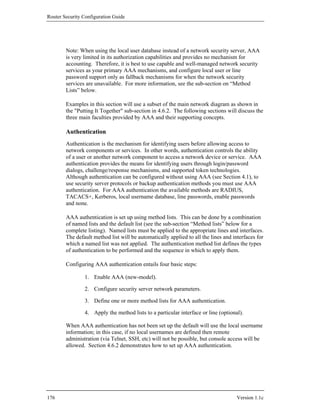
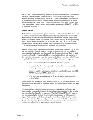
![Router Security Configuration Guide
Section 4.6.2 shows an example of configuring AAA authorization. For more
detailed information about configuring authorization using AAA, refer to the
“Configuring Authorization” chapter in the IOS Security Configuration Guide [1].
Accounting
AAA accounting is used for logging and tracking the activities of users (people or
other network components) using a network resource. These logs can be used for
network management, security analysis, resource usage tracking, and reporting.
Routers send their accounting records to the security server for storage. Information
in an accounting record includes the user’s identity, the usage start and stop times,
number of packets and bytes, and the command that was executed. AAA accounting
can only use the TACACS+ or RADIUS security servers for record logging.
As with authentication and authorization, you configure AAA accounting by defining
a list of accounting methods. If the list was a named list then it must be applied to
the appropriate lines and interfaces. The list will define the list of accounting
methods for the indicated accounting type. For an accounting type, if a default list is
not defined and a named list is not applied to the line then no accounting will occur
for that type on that line.
There are several types of accounting which can be enabled and configured
separately: exec, network, connection, command, system. All types are supported by
TACACS+, but RADIUS does not support command or system.
• network accounting – Provides information for PPP, SLIP, and ARAP
protocols. The information includes the number of packets and bytes.
• EXEC accounting – Provides information about user EXEC sessions on
the router. The information includes the username, date, start and stop
times, IP address of access server, and telephone number the call
originated from for dial-in users.
• connection accounting – Provides information about all outbound
connections made from the network access server. This includes telnet,
rlogin, etc.
• command accounting – This applies to commands which are entered in an
EXEC shell. This option will apply accounting to all commands issued at
the specified privilege level. If accounting is turned on for level 15 and
user logged in at enable level 15 runs a level 1 exec command no
accounting event will be generated. Account records are generated based
upon the level of the command not the level of the user. Accounting
records will include the command, date, time, and the user. Cisco IOS
does not support command acccounting with RADIUS.
• system – Provides information about system-level events. This would
include information like system reboots, accounting being turned on or off,
178 Version 1.1c](https://image.slidesharecdn.com/c4-040r-02-130310054952-phpapp01/85/C4-040-r-02-178-320.jpg)
![Advanced Security Services
etc. Note that system accounting will only use the default list. Cisco’s
implementation of RADIUS does not support system accounting.
AAA accounting requires that AAA is enabled, security servers are defined, and that
a security server is specified for each accounting type which is desired. Each
accounting record is comprised of accounting AV pairs and is stored on the access
control server. Accounting can also be configured such that a user requested action
can not occur until an acknowledgement is received from the security server stating
that the accounting record has been saved.
Section 4.6.2 gives an example of configuring accounting. For more information
about AAA accounting, including RADIUS and TACACS+ attributes, see the IOS
Security Configuration Guide [1].
Method Lists and Server Groups
Method lists are used to specify one or more security protocols or mechanisms for
AAA. Method lists also specify the sequence in which the security mechanisms
should be used. These lists can be used to provide backup mechanisms for when the
primary security method is unavailable. For AAA the Cisco IOS software will use
the first method listed to perform the authentication, authorization, or accounting as
appropriate. If the Cisco IOS software is unable to complete the task due to failure to
communicate with the security server or mechanism then the Cisco IOS will try the
next method in the list. This continues until there is a successful communication with
a listed method or the list is exhausted. If the list is exhausted then the operation will
fail. In the case of authentication and authorization the user will be denied access. In
the case of accounting the auditing event will not occur, except for wait-start
accounting which will also deny the user access for the service. A negative response
from a security server will also deny access in the case of authentication and
authorization and the next method in the list will not be attempted. (Note: the local
user database is treated as a special case; if the user supplies a username that does
not exist in the local user database then the next method on the list will be attempted.
Other mechanisms, like RADIUS, TACACS+, and Kerberos security servers, will
deny access if the username does not exist.)
Method lists can be given a specific name or can use the keyword “default”. When a
method list is specified using the default keyword the list will be applied to all the
appropriate interfaces and lines automatically. Named method lists can then be
defined and then applied to particular ports or lines to override the default behavior.
This also means that a named method list will have no effect on a interface or line
unless it has been applied to it.
It is important to choose the right order for the methods on a method list, especially
for authentication. For AAA login authentication, the first method on the list
determines whether the user will be prompted for a username. Methods requiring
only a password (e.g. the “line” method) should never be placed ahead of methods
requiring a both username and password, because the user will never be prompted for
a username and the mechanism will always fail.
Version 1.1c 179](https://image.slidesharecdn.com/c4-040r-02-130310054952-phpapp01/85/C4-040-r-02-179-320.jpg)
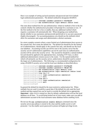
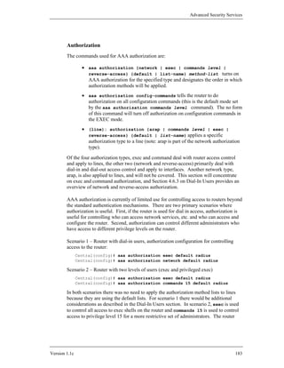
![Router Security Configuration Guide
commands turn on the checks to query the security server on the router but the actual
user to authorization privilege mapping occurs on the security server.
RADIUS and TACACS+ authorization both define specific rights for users by
processing attributes, which are stored in a database on the security server. For both,
RADIUS and TACACS+, attributes are defined on the security server, associated
with the user, and sent to the network access server where they are applied to the
user's connection. For a list of supported RADIUS attributes, refer to the "RADIUS
Attributes" appendix of [1]. For a list of supported TACACS+ A-V pairs, refer to the
"TACACS+ Attribute-Value Pairs" appendix of [1].
The local database is populated using the username command. But there are no
useful parameters to set for access to the router from lines (an exception would be for
dial-in access). Important: do not use the username name privilege level command
since the password will be weakly protected. Protect higher levels on the router
using the enable secret command (see Section 4.1).
Also, in the examples above if the RADIUS security server is not available no one
will be able to get an exec shell and in scenario 2 no one will be able to run privilege
level 15 commands. There is one very important exception to this, AAA
authorization does not apply to the console line. Even if a named method list is
created and applied to the console line authorization will be ignored.
Accounting
The commands used for AAA accounting are:
• aaa accounting {system | network | exec | connection |
commands level} {default | list-name} {start-stop | wait-
start | stop-only | none} method-list turns on AAA's
accounting services for the specified accounting type.
• aaa accounting suppress null-username command prevents
accounting records from being generated for those users who do not have
usernames associated with them. (NULL usernames can occur because of
accounting records on a protocol translation)
• aaa accounting update {newinfo | periodic number} will allow
administrators to specify when accounting records are sent to security
servers. Periodic generates more accounting records than newinfo since it
will also include interim reports on actions in progress.
• (line): accounting {arap | commands level | connection |
exec} [default | list-name] can be used to apply different
accounting services and levels to different lines.
• show accounting {system | network | exec | commands level}
{start-stop | wait-start | stop-only} tacacs+ command can
184 Version 1.1c](https://image.slidesharecdn.com/c4-040r-02-130310054952-phpapp01/85/C4-040-r-02-184-320.jpg)
![Router Security Configuration Guide
Configuration of RADIUS accounting:
Central(config)# aaa accounting exec default start-stop radius
Central(config)# aaa accounting exec remoteacc wait-start radius
Central(config)# aaa accounting connection default start-stop
radius
Central(config)# line vty 0 4
Central(config-line)# accounting exec remoteacc
Central(config)# line aux 0
Central(config-line)# accounting exec remoteacc
Since remote administration is more dangerous than console administration, the
configurations above add extra accounting to the remote lines. Part of the extra
protection is requiring that before a remote user can get an exec shell an audit record
must be recorded into the security server. Note: the aux line configuration is not
required if the aux line is disabled as suggested in Section 4.6.2. Also, for
information about RADIUS Attributes and TACACS+ AV Pairs for use in
accounting, refer to the appendices in the Cisco Security Configuration Guide [1].
Putting It Together
This section will put together the AAA mechanisms from earlier in this section and
will apply them to the configuration of the Central and South Routers. The Central
router is between the facility backbone and the specific part of the infrastructure. The
South router acts as the first layer of defense to a well protected enclave.
Facility Network eth 0 eth 1
14.1.0.0/16 East
14.1.1.20 14.2.6.250 Authentication
Server
14.2.6.18
LAN 1
14.2.6.0/24
eth 0/0 14.1.15.250
Central
eth 0/1
14.2.9.250
eth 0/0
LAN 2 14.2.9.64/24
South
14.2.9.0/24
eth 0/1 14.2.10.64
Protected Enclave
14.2.10.0/24
Figure 4-12: Routers and their Authentication Server
Authorization will not be used in these examples since all the administrators in these
examples need configuration access and there is no dial-in access. For a more
186 Version 1.1c](https://image.slidesharecdn.com/c4-040r-02-130310054952-phpapp01/85/C4-040-r-02-186-320.jpg)
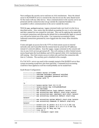
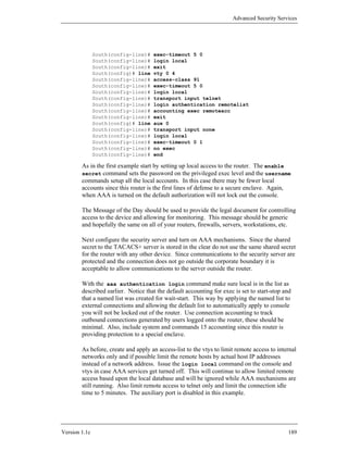
![Router Security Configuration Guide
If a RADIUS server was used in this example instead of the TACACS+ server then
system and command accounting would not be specified.
4.6.3. Dial-In Users
AAA services were designed with remote network access in mind. This includes
remote access to routers as well as to network services like PPP. AAA using
RADIUS is one of the primary means by which this is accomplished by Internet
Service Providers (ISP's). Controlling access for dial-in users is similar to
controlling access to the router but there are different protocols that are used.
Additionally, although it is not shown, it is highly recommended that when dial-in
access to the network or router is in use, that AAA services should be used in
conjunction with a one-time password or similar token technology. Some important
commands for controlling dial-in users are:
• aaa authentication ppp {default | list-name} <method-list> is
used to specify PPP authentication method lists.
• aaa authorization {network | exec | commands level | reverse-
access} {default | list-name} <method-list> turns on AAA
authorization for the specified type and designates the order in which
authorization methods will be applied. In this case we are particularly
interested in turning on network authorization.
• aaa accounting {system | network | exec | connection |
commands level } {default | list-name} {start-stop | wait-
start | stop-only | none} method-list turns on AAA's accounting
services for the specified accounting type. For dial-in users network needs
to be used.
• aaa processes number command is used to specify the number of
background processes to start to handle concurrent authentication and
authorization requests.
• (interface): ppp authentication {pap | chap | pap chap | chap
pap} [if-needed] {default | list-name} [call-in] [one-tone]
command is used to enable pap, chap, or both forms of authentication on
the selected interface.
• (interface): ppp authorization {default | list-name}
command is used to apply a ppp authorization list to the selected interface.
• (interface): ppp accounting [default | list-name] command is
used to apply accounting methods to the PPP service on the selected
interface.
The example below gives one potential application of AAA services for dealing with
dial-in services (Note: this example is not complete). Figure 4-13 shows the relevant
portion of the network, and the configuration for East is shown after it.
190 Version 1.1c](https://image.slidesharecdn.com/c4-040r-02-130310054952-phpapp01/85/C4-040-r-02-190-320.jpg)
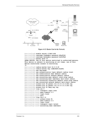
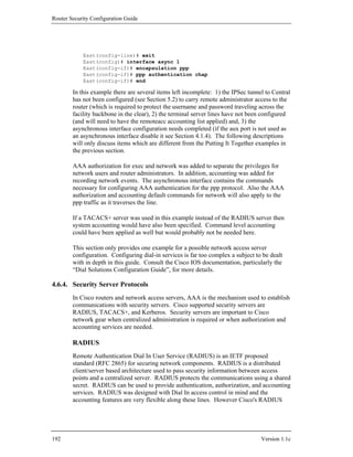
![Advanced Security Services
client does not support auditing of command or system events on the router or
network access server.
As a minimum when setting up a RADIUS server on a Cisco device the host address
and shared secret must be configured as well as turning on and configuring AAA on
the device. This is accomplished using the commands listed:
• radius-server host {hostname | ip-address} [auth-port
port-number] [acct-port port-number] command specifies the
radius server's hostname or IP address and the ports to use for
authentication (authorization) and accounting.
• radius-server key string sets the RADIUS server shared
encryption key. The secrecy and quality of this key is critical to the
security of your RADIUS installation; users never have to type this string,
so make it longer than a typical password. The shared secret key should be
at least 16 characters long and follow the other rules for a good password
as described in Section 4.1.4.
Also, the RADIUS service should be bound to the loopback0 interface, if you have
defined it as described in Section 4.1.4. For a complete list of RADIUS router
configuration commands see the “RADIUS Commands” section in [1]. The example
below shows how to set up RADIUS on the router Central.
Central(config)# ip radius source-interface loopback0
Central(config)# radius-server host 14.2.6.18
Central(config)# radius-server key W@t7a8y-2m@K3aKy
RADIUS servers are freely available and are in extensive use. To perform
authentication and authorization a RADIUS server uses attributes. These attributes
can be configured to allow/deny access to various router and network services. For
more details see the Security Configuration Guide on "Configuring RADIUS" and
"RADIUS Attributes" sections for more details.
Some RADIUS servers use the old standard port 1645 for authentication, while
others use the new standard port of 1812. IOS always uses 1645 unless you specify
otherwise. Use the auth-port parameter to cause IOS to send RADIUS requests to the
server on that port.
East(config)# radius-server host 14.2.6.18 auth-port 1812
Under IOS 12.1 or later, you can define named groups of RADIUS servers. These
groups may be useful for large enterprises, where different sets of security servers are
used for different groups of users or different purposes. To define a server group, use
the command aaa server group, as shown below.
! RADIUS example - a group with one server in it
Central(config)# aaa server group radius radGroup1
Central(config-sg)# server 14.2.6.18 auth-port 1812
Central(config-sg)# server 14.2.6.18 key i*Ma5in@u9p#s5wD
Central(config-sg)# end
Central#
Version 1.1c 193](https://image.slidesharecdn.com/c4-040r-02-130310054952-phpapp01/85/C4-040-r-02-193-320.jpg)
![Router Security Configuration Guide
To use a server group, name it in a method list instead of the default group ‘radius’.
Central(config)# aaa authentication login VTlogin group radGroup1
TACACS+
Terminal Access Controller Access Control System plus (TACACS+) is the most
recent Cisco security protocol designed to provide accounting and flexible control of
authentication and authorization services. TACACS+ is implemented by Cisco using
the AAA mechanisms and provides for the centralized validation of users using
routers and network services. TACACS+ protects communications using a shared
secret key between the network device and central server. TACACS+ was designed
with Cisco implementations in mind so it offers a wide range of AAA services
including full auditing of Cisco AAA accounting events.
The primary commands used for configuring TACACS+ on a Cisco router are:
• tacacs-server host {hostname | ip-address} [port port-
number] [key string] command can be used to specify the host, IP
address or DNS name, where the TACACS+ server is running. The [port
integer] can be used to specify a new port number. The key string
parmeter sets the secret key for this TACACS+ server host overriding the
default but should follow same creation rules as the default.
• tacacs-server key string command sets the default TACACS+
shared encryption key. The security of TACACS+ depends on this secret,
and users never have to type it, so make it longer than a typical login
password. The shared secret key should be at least 16 characters long and
follow all the rules for a good password as described in Section 4.1.4.
For a complete list of TACACS+ router configuration commands see the "TACACS,
Extended TACACS, and TACACS+ Commands" section in the "Security
Command Reference". Simple example for Central:
Central(config)# tacacs-server host 14.2.6.18
Central(config)# tacacs-server key W@t7a8y-2m@K3aKy
TACACS+ implementations are available through Cisco Secure ACS and Cisco also
offers a free implementation as well. TACACS+ uses attribute-value pairs for
controlling authentication and authorization services. These attribute-value pairs are
configured on the server and used by the router authorization mechanism to control
access to network services. For more details on the TACACS+ and attribute-value
pairs see the Security Configuration Guide sections “Configuring TACACS+” and
“TACACS+ Attribute-Value Pairs”.
Under IOS 12.1 or later, you can define named groups of TACACS+ servers. These
groups may be useful for large enterprises, where different sets of security servers are
194 Version 1.1c](https://image.slidesharecdn.com/c4-040r-02-130310054952-phpapp01/85/C4-040-r-02-194-320.jpg)
![Advanced Security Services
used for different groups of users or different purposes. To define a server group, use
the command aaa server group, as shown below.
! TACACS+ Example - a group with two servers in it
Central(config)# aaa server group tacacs+ myTacGroup
Central(config-sg)# server 14.2.6.18 key Gx98-vAR1bv*u
Central(config-sg)# server 14.2.10.39 key t777+08cdcoWW
Central(config-sg)# end
Central#
When you want to include the servers of a particular group in a method list, simply
use the group name instead of the default name ‘radius’ or ‘tacacs+’.
Central(config)# aaa authentication login VTlogin group myTacGroup
Kerberos
Kerberos was developed by the Massachusetts Institute of Technology (MIT) and is
standardized by the IETF as a network authentication system in RFC 1510. Kerberos
provides strong authentication for client/server applications by using secret-key
cryptography. This mechanism can verify the identities of two users (i.e. person or
network component) on unprotected networks. This authentication is performed
using a trusted third-party service using conventional (secret key) cryptography. In
this system a client would request the credentials of the party they wish to contact
from the trusted authentication service. The communications between the router and
the Kerberos security server are encrypted.
Kerberos can also be used to perform EXEC shell authorization using Kerberos
Instance Mapping. After the two parties have been authenticated (in this case, the
router and the adminstrator), Kerberos can provide very effective confidentiality and
data integrity services, if your Telnet client supports Kerberos encryption. These two
topics are outside the scope of the Kerberos coverage in this guide, consult the IOS
12.1 Security Configuration Guide for more information.
Kerberos infrastructures are already in wide use. If you already have a Kerberos
infrastructure in place, then this form of centralized authentication may be a way to
gain excellent security for remote administration. Note that Kerberos only allows for
limited authorization capabilities and no accounting. There are free open sources
versions of Kerberos available as well as commercially supported products. Some
modern operating systems come with Kerberos built in. Configuration of a Microsoft
Windows 2000 Server acting as the Kerberos authentication server is covered below.
Configuration of Kerberos installations based on MIT Kerberos are already explained
in the Cisco IOS documentation. Host configuration for using MIT Kerberos is not
covered in this guide, but more details can be found in the IOS documentation [1], as
well as in RFC 1510 [5] and in Tung’s book [8].
This section assumes basic familiarity with Kerberos administration and security
concepts. For a good introduction to these topics, consult [8]. Before attempting
any of the step below, make sure that the IOS installed on your router supports
Version 1.1c 195](https://image.slidesharecdn.com/c4-040r-02-130310054952-phpapp01/85/C4-040-r-02-195-320.jpg)
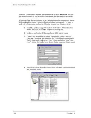
![Advanced Security Services
5. Check the Kerberos settings for logins; use the settings shown below in
the column “Effective Setting”. For more information, consult the NSA
Guide to Windows 2000 Kerberos Settings [6].
6. Use the Windows ktpass command, installed in step 1, to create the
host’s keytab file, map the router to its account, and set its password.
7. Install the keytab file on the router. This must be done using the IOS
kerberos srvtab command, as shown below.
Once you are sure that your router supports Kerberos, follow the steps listed below
in global config mode.
1. Define the Kerberos realm.
kerberos local-realm kerberos-realm
2. Designate the Kerberos KDC to use in the realm, along with port
number.
kerberos server kerberos-realm
{hostname | ip-address} [port-number]
3. Map an optional host name or DNS domains to the realm.
Version 1.1c 197](https://image.slidesharecdn.com/c4-040r-02-130310054952-phpapp01/85/C4-040-r-02-197-320.jpg)
![Router Security Configuration Guide
kerberos realm {dns-domain | host} kerberos-realm
4. Define the preauthentication method.
kerberos preauth authentication-method
The recommended method is encrypted-kerberos-timestamp.
5. Generate a local private DES key. The key-password should be 8
randomly-chosen characters.
key config-key 1 key-password
The key will be used to encrypt the Kerberos secret key in the router’s
stored configuration. (This key is stored in the router’s NVRAM, but
cannot be recovered or extracted.)
6. Load the keytab file from a server, link channel, or local file.
kerberos srvtab remote { URL | host filename }
This command supports a wide variety of means for downloading the
srvtab file, including TFTP, FTP, and more. TFTP is the default.
7. Create a login authentication model, specifying Kerberos as the
mechanism to use first.
aaa authentication login {default | list-name}
krb5 [ {other-mechanisms} ]
The two examples below show two different ways of conveying the Kerberos keytab
file, generated by the Windows 2000 ktpass command, over to the router. Neither
approach is perfect -- the ideal approach would be to load the keytab file directly over
the serial link, but unfortunately that is not supported in any version of IOS that the
authors of this guide have been able to test.
Kerberos Example 1: Network Download
The transcript below shows an example of following the Kerberos setup procedure on
router Central. In this case, the Kerberos KDC provides service on IP address
14.2.6.18, and a TFTP server is on IP address 14.2.9.6. (Note: Windows 2000
installations typically do not include TFTP servers. You will need to use a
commercial TFTP server, or distribute the file from a Unix system equipped with a
TFTP server.)
Central# config t
Enter configuration commands, one per line. End with CNTL/Z.
Central(config)# kerberos local-realm KERBEROS.NSA.GOV
Central(config)# kerberos server KERBEROS.NSA.GOV 14.2.6.18
Central(config)# kerberos realm kerberos.nsa.gov KERBEROS.NSA.GOV
Central(config)# kerberos realm .kerberos.nsa.gov KERBEROS.NSA.GOV
Central(config)# kerberos preauth encrypted-kerberos-timestamp
Central(config)# key config-key 1 aW.-8(xZ
Central(config)# kerberos srvtab remote 14.2.9.6 Central.keytab
Loading Central.keytab from 14.2.9.6 (via Ethernet0/1): !
[OK - 78/4096 bytes]
Central(config)#
198 Version 1.1c](https://image.slidesharecdn.com/c4-040r-02-130310054952-phpapp01/85/C4-040-r-02-198-320.jpg)
![Advanced Security Services
The content of the keytab file is very sensitive, because it contains the long-term
Kerberos secret key that the router will use to communicate with the KDC. In
general, it is not a good idea to transfer the keytab file from your server to the router
over TFTP (or FTP, or any other plaintext network protocol). Unless this part of
your configuration takes place on an isolated lab or management network, do not use
this method to distribute the keytab file. Instead, use (1) the console serial download
method described below, or (2) the SCP protocol instead of TFTP (this requires IOS
support for SCP, and it requires setting up SSH as described in Section 5.5).
Kerberos Example 2: Console Link Download
This example shows how to convey the keytab file securely from your server to the
router over the console serial link using the YModem protocol.
Central# copy ymodem: flash:central.key
**** WARNING ****
.
.
Proceed? [confirm]y
Destination filename [central.key]? central.key
Erase flash: before copying? [confirm]n
Max Retry Count [10]: 15
Perform image validation checks? [confirm]n
Ymodem download using crc checksumming with NO image validation
Continue? [confirm]y
Ready to receive file...........C
4294967295 bytes copied in 23.692 secs (0 bytes/sec)
Central#
Central# config t
Enter configuration commands, one per line. End with CNTL/Z
Central(config)# kerberos local-realm KERBEROS.NSA.GOV
Central(config)# kerberos server KERBEROS.NSA.GOV 14.2.6.18
Central(config)# kerberos realm kerberos.nsa.gov KERBEROS.NSA.GOV
Central(config)# kerberos realm .kerberos.nsa.gov KERBEROS.NSA.GOV
Central(config)# kerberos preauth encrypted-kerberos-timestamp
Central(config)# key config-key 1 .XT9+se%
Central(config)# kerberos srvtab remote flash:central.key
Central(config)# exit
Central# ! optional steps: wiping the keytab from flash
Central# delete flash:central.key
Delete filename [central.key]? central.key
Delete flash:central.key? [confirm]y
Central#
Central# ! the squeeze command may not be supported on all routers
Central# squeeze flash:
Squeeze operation may take a while. Continue? [confirm]y
.
.
Central#
Version 1.1c 199](https://image.slidesharecdn.com/c4-040r-02-130310054952-phpapp01/85/C4-040-r-02-199-320.jpg)
![Router Security Configuration Guide
Kerberos and AAA
Once you have downloaded the keytab file, you can designate Kerberos as your main
AAA authentication method.
Central(config)# aaa new-model
Central(config)# aaa authentication login default krb5 local
Central(config)# exit
Central#
This section presents only a very cursory look at Kerberos authentication. For more
information about administering Kerberos networks, consult [6], [7], and [8].
4.6.5. References
[1] Cisco Systems, Cisco IOS 12.0 Network Security, Cisco Press, 1999.
This book provides a detailed reference for all the security features in Cisco
IOS 12. It includes a great deal of information about AAA, including a
section on configuring Kerberos. The same information is also available in
the on-line documentation, in the Cisco IOS Security Configuration Guide.
[2] Cisco System, Cisco IOS 12.0 Dial Solutions, Cisco Press, 1999.
This documentation volume provides detailed information on setting up
modems and dial-up networking facilities.
[3] Rigney C., et. al. “Remote Authentication Dial In User Service (RADIUS)”
RFC 2865, June 2000.
This is the Internet RFC that defined the core RADIUS protocol.
[4] Carrel, D., and Grant, L. “The TACACS+ Protocol Version 1.78”, Cisco
Systems, January 1997.
available at: ftp://ftpeng.cisco.com/pub/tacacs/tac-rfc.1.78.txt
This is the draft RFC that would have standardized the TACACS+ protocol.
It explains the operation of the protocol in great detail.
[5] Kohl, J., “The Kerberos Network Authentication Service (V5)”, RFC 1510,
September 1993.
This is the Internet RFC that defines the Kerberos authentication protocol.
[6] Opitz, D. “Guide to Windows 2000 Kerberos Settings” NSA, July 2001.
available under: http://www.nsa.gov/ia/
This guide describes prudent Kerberos security settings for Windows 2000.
200 Version 1.1c](https://image.slidesharecdn.com/c4-040r-02-130310054952-phpapp01/85/C4-040-r-02-200-320.jpg)
![Advanced Security Services
[7] “Step-by-Step Guide to Kerberos 5 Interoperability,” Windows 2000 Step-by-
Step Guides, Microsoft Corporation, 2002.
available at: http://www.microsoft.com/windows2000/techinfo/
planning/security/kerbsteps.asp
This article describes how to use Windows 2000 Kerberos with other
Kerberos implementations.
[8] Tung, B., Kerberos - A Network Authentication System, Addison-Wesley, 1999.
This slim handbook provides a good overview of Kerberos.
Version 1.1c 201](https://image.slidesharecdn.com/c4-040r-02-130310054952-phpapp01/85/C4-040-r-02-201-320.jpg)
![Router Security Configuration Guide
Consult the Cisco IOS 12.0 Security Configuration Guide [2] for details on the other
IKE options.
(Note: the router used for part of this example is named “Remote”, and that name
appears in all the prompts. Do not use a remote administration connection to enter
sensitive IPSec parameters – use a local console connection.)
To use pre-shared keys for making authentication decisions in IKE, each router must
possess the same secret key. These keys should be obtained out-of-band by each of
the routers’ administrators. Once the keys are securely held, the network
administrators for the North and Remote routers (possibly the same person) should
enter the key into their routers. For this example, the secret key is “01234abcde”. We
strongly recommend using difficult-to-guess combinations of characters, numbers,
and punctuation symbols to build operational pre-shared keys. To enter the keys, use
the crypto isakmp command in global configuration mode, as shown below.
The syntax for the crypto isakmp command is: crypto isakmp key key-value
address destination-ip-address.
North# config t
Enter configuration commands, one per line. End with CNTL/Z.
North(config)# crypto isakmp key 01234abcde address 7.12.1.20
North(config)# exit
North#
and
Remote# config t
Enter configuration commands, one per line. End with CNTL/Z.
Remote(config)# crypto isakmp key 01234abcde address 14.2.0.20
Remote(config)# exit
Remote#
When entering new configuration information into the router it is always a good idea,
after entering the new information, to check and see if the router has received the
intended configuration information. One way to verify that the pre-shared keys were
properly entered is to display the router’s running-configuration and look for the pre-
shared key entered above. This can be done using the show running-config
command in privileged EXEC mode.
Establishing an IKE Security Policy
Each router contains a list of IKE security polices. In order for two routers to be
interoperable, there must be at least one policy in common between them. These
policies capture information needed by the IKE protocol to help build a secure IPSec
tunnel between the two routers. Each necessary parameter for the policy is listed
206 Version 1.1c](https://image.slidesharecdn.com/c4-040r-02-130310054952-phpapp01/85/C4-040-r-02-206-320.jpg)
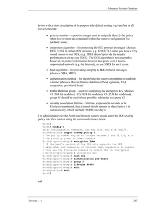
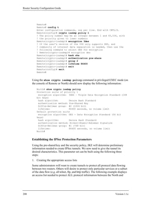
![Router Security Configuration Guide
an application behind the router which is pushing data through the tunnel, but adding
it can improve defense in depth. In the following example, the ESP protocol is
chosen with both data protection and authentication properties applied to all
information transmitted between the North and Remote routers.
The transform set also specifies what part of each packet is protected by the IPSec
tunnel. For a hostile network scenario, the preferred mode is tunnel (which is the
default). This mode protects both the original data portion of the IP packet and the
original packet header, and creates a new IP header using the routers’ IP addresses.
This hides potentially sensitive IP protocol information about the networks and
applications that are sending data through the tunnel. If the IPSec tunnel is used for
separating communities of interest over a protected network, then the transport mode
will be sufficient. This mode protects the original data portion of the IP packet, but
leaves the original IP header intact. The IPSec standards requires that tunnel mode be
used when routers are employed as gateway security devices. For more information
on both the encryption and authentication algorithms, and the tunnel modes, consult
the Cisco IOS 12.0 Security Configuration Guide [2].
The command syntax for defining an IPSec transform set is: crypto ipsec
transform-set transform-set-name transform1 transform2 . . .
transformN. When you give this command, IOS will enter crypto transform set
configuration mode, to which you can give a variety of transform-set related
commands. Use exit to leave transform set configuration mode.
Configure the IPSec transform sets using the following commands:
North# config t
Enter configuration commands, one per line. End with CNTL/Z.
North(config)# crypto ipsec transform-set set1 esp-3des esp-sha-hmac
! The name set1 is an arbitrary name
North(cfg-crypto-trans)# mode tunnel
North(cfg-crypto-trans)# end
North#
and
Remote# config t
Enter configuration commands, one per line. End with CNTL/Z.
Remote(config)#crypto ipsec transform-set set1 esp-3des esp-sha-hmac
! The name set1 is an arbitrary name
Remote(cfg-crypto-trans)# mode tunnel
Remote(cfg-crypto-trans)# end
Remote#
3. Create the necessary crypto map
Cisco IOS uses crypto maps to bring together all information needed to create IPSec
tunnels. This information includes: the access-list to specify what traffic should be
protected (covered above in section 1), the transform-set used to build the tunnel
(covered above in section 2), the remote address for the peer end of the IPSec tunnel,
the security association lifetime for the tunnel (in kilobytes and/or seconds), and
210 Version 1.1c](https://image.slidesharecdn.com/c4-040r-02-130310054952-phpapp01/85/C4-040-r-02-210-320.jpg)
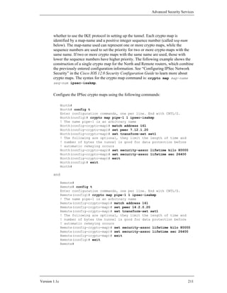
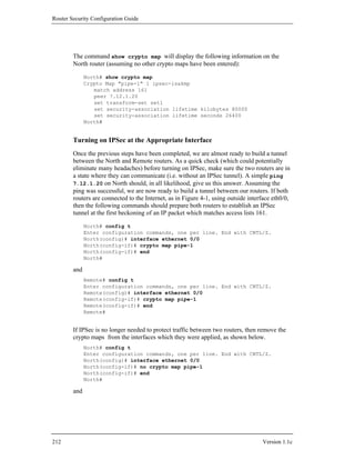
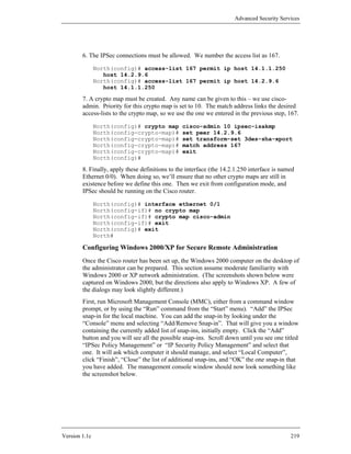
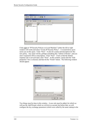
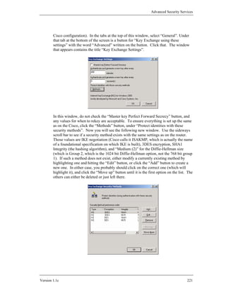
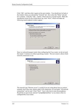
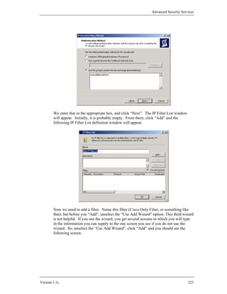
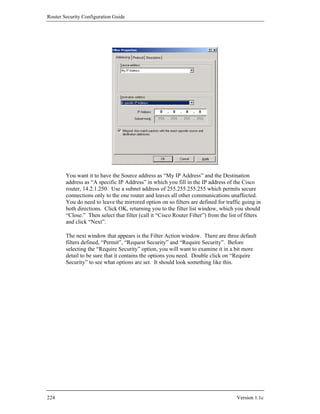
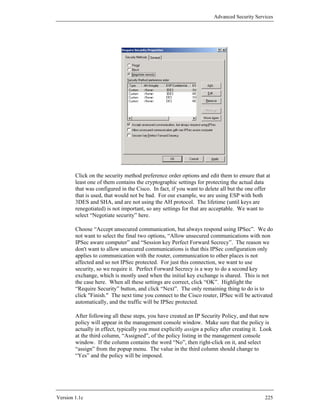

![Advanced Security Services
5.3. Using SSH for Remote Administration Security
An alternative to setting up IPSec for secure remote administration is to configure
your router to use the secure shell service, commonly called SSH. SSH was
originally intended to be a secure replacement for classic telnet, rlogin, rsh, and rcp
services. It utilizes RSA public key cryptography to establish a secure connection
between a client and a server. Because the connection is encrypted, passwords and
other sensitive information are not exposed in the clear between the administrator’s
host and the router. SSH also prevents session hijacking and many other kinds of
network attacks. For a thorough discussion of SSH, consult [13].
Only certain Cisco IOS versions are shipped with the SSH feature set. Versions after
and including 12.0(5)S with IPSec include support for SSH. IOS versions that do not
support IPSec usually do not support SSH either. For more information about IOS
versions, see Section 8.3. There are two main versions of the SSH protocol in
widespread use, SSH versions 1 and 2. Cisco IOS 12.0 through 12.3 are currently
capable of supporting only SSH version 1. IOS 12.4 can support SSH version 2.
Before you can configure SSH, there are two important prerequisites to address.
First, make sure that the router has a local hostname and domain name set.
Instructions for this can be found in section 4.2.2. With SSH, you must establish
usernames for people that will be attempting to connect to the router. See Section 4.6
for detailed information on how to define usernames.
The detailed example below shows how to configure the router North (14.1.1.250) to
run the SSH server and accept incoming connections. In this scenario the
administrator will use an SSH client on the host 14.2.9.1 to connect to the router for
administrative purposes.
5.3.1. Configuring a Router for Secure Remote Administration with SSH
While in IOS enable mode, perform the following steps:
1. Enter configuration mode:
North# config t
Enter configuration commands, one per line. End with CNTL/Z.
North(config)#
2. Configure an access list permitting access from the administrative host. This
example uses standard IP access list 12 to identify the hosts that may start SSH
sessions into router North. For more information about access lists, see Section 4.3.
North(config)# no access-list 12
North(config)# access-list 12 permit host 14.2.9.1 log
North(config)# line vty 0 4
North(config-line)# access-class 12 in
North(config-line)# exit
Version 1.1c 227](https://image.slidesharecdn.com/c4-040r-02-130310054952-phpapp01/85/C4-040-r-02-227-320.jpg)
![Router Security Configuration Guide
3. Set up a username that is permitted to connect to the router. If you have already
created user accounts (with or without AAA), as specified in section 4.6, you may
skip this step.
North(config)# username joeadmin password 0 1-g00d-pa$$word
North(config)# line vty 0 4
North(config-line)# login local
North(config-line)# exit
North(config)#
To act as an SSH server, the router must possess an RSA key pair. If the router
already has a key pair, perhaps generated as part of its IPSec configuration, then you
may use it for SSH. Otherwise, generate a new RSA key pair for this router. If you
need to remove an old key pair, and you are absolutely sure that the keys are not
being used, then you may delete them using the command crypto key zeroize
rsa. To generate a new key pair, use the command crypto key generate as
shown below. (Note: you must assign a domain name before creating a key; see
Section 4.2.2 for direction.) Cisco suggests a minimum modulus size of 1024 bits.
North(config)# crypto key generate rsa
The name for the keys will be: North.dod.mil
Choose the size of the key modulus in the range of 360 to
2048 for your General Purpose Keys. Choosing a key modulus
greater than 512 may take a few minutes.
How many bits in the modulus [512]: 2048
Generating RSA Keys ...
[OK]
North(config)#
If this command succeeds, the SSH server is enabled and running. By default, the
SSH service will be present on the router whenever an RSA key pair exists, but it will
not be used until you configure it, as detailed below. If you delete the router’s RSA
key pair, then the SSH server will stop. Note: check carefully before deleting a key
pair, because there is no way to recover a private key that has been deleted.
Below are some useful commands for further configuring the new SSH server.
• Configure an authentication timeout. This is the number of seconds the
server will wait for a client to respond with a password. Once the
connection is established, standard vty timeout settings apply. The default
authentication timeout is 120 seconds, which is also the maximum allowed
value. The recommended value is 90. To change this from the default, do
the following.
North(config)# ip ssh time-out 90
North(config)#
228 Version 1.1c](https://image.slidesharecdn.com/c4-040r-02-130310054952-phpapp01/85/C4-040-r-02-228-320.jpg)
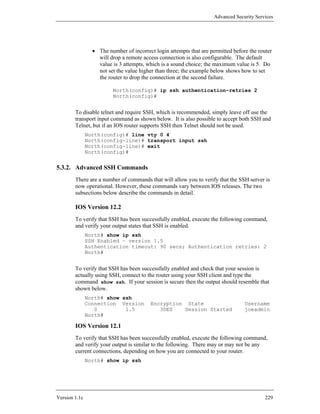
![Advanced Security Services
5.3.3. Some Available SSH Clients
To employ SSH between an administrative host and the router, the host must support
an SSH client. There are usable clients available for almost every host platform
(even PDAs), and most Unix and Linux distributions include an SSH client by
default. Below are some useful clients for common host operating systems.
Information on where to download these applications can be found in the Tools
listing, Section 9.3.
Unix / Linux
• OpenSSH (freeware)
• SSH Secure Shell (commercial)
Windows
• PuTTY (freeware)
• TTSSH Plugin for TeraTerm Pro (freeware)
• SecureCRT (commercial)
• SSH Techtia client (commercial)
MacOS
• NiftyTelnet 1.1 (freeware)
5.3.4. Security of SSH Versions
There are several known security weaknesses with the SSH version 1 protocol.
Attacks that exploit these weaknesses are complex and non-trivial to execute, but
tools that implement some of them do exist. Even though SSH version 1 may be
subject to network man-in-the-middle attacks in some circumstance, it is still a much
more secure choice for remote administration than unprotected Telnet. For more
information about vulnerabilities in SSH and Cisco IOS, consult [12].
When your IOS release supports SSH version 2, configure the router to use it
exclusively as shown below.
North(config)# ip ssh version ?
<1-2> Protocol version
North(config)# ip ssh version 2
North(config)# exit
North# show ip ssh
SSH Enabled - version 2.0
Authentication timeout: 90 secs; Authentication retries: 2
North#
Version 1.1c 231](https://image.slidesharecdn.com/c4-040r-02-130310054952-phpapp01/85/C4-040-r-02-231-320.jpg)
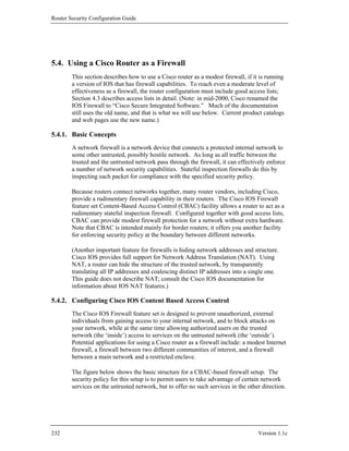
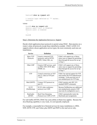
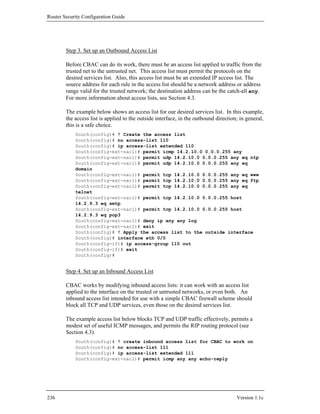
![Advanced Security Services
South(config-ext-nacl)# permit icmp any any unreachable
South(config-ext-nacl)# permit icmp any any ttl-exceeded
South(config-ext-nacl)# permit icmp any any packet-too-big
South(config-ext-nacl)# permit udp any any eq rip
South(config-ext-nacl)# deny ip any any log
South(config-ext-nacl)# exit
South(config)# ! apply the access list to the outside interface
South(config)# interface eth 0/0
South(config-if)# ip access-group 111 in
South(config-if)# exit
South(config)#
Step 5. Create a CBAC Ruleset
To create a CBAC ruleset, use the command ip inspect name. The syntax is
shown below.
ip inspect name ruleset-name protocol [alert on/off]
[audit-trail on/off] [timeout override-timeout]
The alert option controls whether use of that protocol causes a console alert
message to be generated; similarly, the audit-trail option controls whether use
of that protocol causes a log message to be generated. Enable the alert and audit-trail
features to get additional log messages, beyond those generated by interface access
lists. (In older versions of CBAC, audit trails could only be turned on globally, using
the command ip inspect audit-trail.)
The example ruleset below supports the example desired service list. The name of
the ruleset is “fw1.” Its first rule supports DNS and NTP, and the second rule
supports web, Telnet, and POP3 email services.
South(config)# ip inspect name fw1 udp audit-trail on
South(config)# ip inspect name fw1 tcp audit-trail on
South(config)# ip inspect name fw1 ftp audit-trail on
South(config)# ip inspect name fw1 smtp audit-trail on
South(config)#
Step 6. Adjust the CBAC Global Parameters
When CBAC detects a connection attempt by a client on the trusted network, it adds
a rule to the inbound access list to permit the expected response. This rule gets
removed when one of the following conditions are satisfied:
• The response does not arrive within the allotted timeout time.
• The connection is idle for longer than an allotted idle time.
• The connection closes down (TCP only).
Version 1.1c 237](https://image.slidesharecdn.com/c4-040r-02-130310054952-phpapp01/85/C4-040-r-02-237-320.jpg)
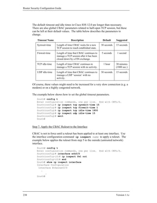
![Advanced Security Services
After this step, CBAC should be running on the router.
Step 8. Test the CBAC Configuration
Perform some simple tests from a host on the trusted network, to see that CBAC is
working. The test shown here has two parts: first, starting a telnet session from a
host on the trusted network to a host on the untrusted network, and second,
confirming that CBAC is managing the session. For more detailed testing
information, see Section 6.
The example below shows a Telnet session from a host on the trusted network
(14.2.10.6) to a host on the untrusted network (14.2.9.250).
$ telnet 14.2.9.250
Trying 14.2.9.250...
Connected to 14.2.9.250.
Escape character is '^]'.
This is the CENTRAL router. Access is limited to
authorized administrators only!
Username: nziring
Password:
Central>
While the Telnet session is active, check the CBAC session status on the router using
the command show ip inspect sessions. It should show the telnet session, as
illustrated in the example below. If the command gives no output, then CBAC is not
working.
South# show ip inspect sessions
Established Sessions
Session 6187B230 (14.2.10.189:3175)=>(14.2.9.250:23) tcp
SIS_OPEN
South#
If the CBAC configuration seems to be working, save the router configuration to
NVRAM at this point with the command copy running startup.
5.4.3. Configuration Sample
The configuration command listing below shows the configuration commands for a
firewall router with a simple CBAC configuration. The desired service list for this
firewall is: DNS, NTP, HTTP, FTP, Telnet, SMTP (to a single host), and POP3 (to a
single host). This sample is formatted as it would appear in a configuration text file
stored on a host for download to the router South.
no access-list 110
ip access-list extended 110
permit icmp 14.2.10.0 0.0.0.255 any
permit udp 14.2.10.0 0.0.0.255 any eq ntp
Version 1.1c 239](https://image.slidesharecdn.com/c4-040r-02-130310054952-phpapp01/85/C4-040-r-02-239-320.jpg)
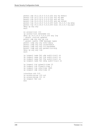
![Router Security Configuration Guide
Note that, after you have configured the router to send alerts to an IDS Director, you
must also configure the Director to accept alerts from the router. If you forget to do
this, the Director will not record the alerts sent by the router.
If the network does not have a Cisco IDS Director available, you should configure
the IDS facility to send alerts as normal IOS log messages using the command shown
below.
South(config)# ! send IDS alerts to syslog and buffered log
South(config)# ip audit notify log
After setting or changing any Post Office parameters, you must save the running
configuration and reboot the router.
South# copy running-config startup-config
Building configuration..
South# reload
Proceed with reload? [confirm] y
.
.
5.5.3. Configuring and Applying Audit Rules
Once you have initialized the IDS and set up the Post Office, you are ready to define
audit rules and apply them to specific interfaces. You define an audit rules by
choosing a name, and then adding one or more specific items to the rule. An item
must be based on either the “info” or “attack” signature classes, and may use standard
IP access lists to limit the addresses to which the signatures are applied (see Section
4.3 for more information on access lists).
For each part of an audit rule, you can designate any or all of three possible actions to
be performed when a signature is matched by traffic.
• drop - discard the packet that triggered the alert
• alarm - log an alert to the Post Office and/or syslog
• reset - cut off the TCP session that matched the signature (TCP only)
Use the config commands ip audit name to add items to an audit rule. The
example below shows how to define a rule named IDR1 containing both info and
attack signatures.
South# config t
Enter configuration commands, one per line. End with CNTL/Z.
South(config)# ip audit name IDR1 info action alarm
South(config)# ip audit name IDR1 attack action alarm drop reset
South(config)#
It is also possible to limit the application of a rule item with a standard IP access list,
although this will raise the performance burden imposed by IDS scanning. Using an
access list, you can restrict the detection of an event, or the actions taken. Because
244 Version 1.1c](https://image.slidesharecdn.com/c4-040r-02-130310054952-phpapp01/85/C4-040-r-02-244-320.jpg)
![Advanced Security Services
only standard IP access lists may be used, you can only restrict scanning by source IP
address. This makes the facility most useful for reducing false positives caused by
specific trusted hosts (e.g. a security audit host used to perform test scans). For
details, consult the IOS documentation.
It is also possible to disable and restrict particular IDS signatures. The example
below shows how to disable two signatures related to common ICMP packet types.
South(config)# ! don’t alert on ICMP source-quench
South(config)# ip audit signature 2002 disable
South(config)# ! don’t alert on ICMP time-exceeded
South(config)# ip audit signature 2005 disable
South(config)#
You can apply a named audit rule on any interface, in either the in-bound or out-
bound directions. Applying the rule in-bound will yield more complete scanning,
because all traffic received on that interface will be scanned. Applying the rule out-
bound will reduce false positives, because only packets which have been permitted
by any in-bound ACLs on other interfaces will be scanned. The example below
shows how to apply our IDR1 rule for traffic coming into the 14.2.10.0 network.
South(config)# interface eth0/0
South(config-if)# description External interface, with IDS
South(config-if)# ip audit IDR1 in
South(config-if)# end
South#
Detection Sample
The transcript below shows the log messages that the IOS Firewall IDS generates and
statistics it records. This session was captured during a small TCP port scan, similar
to the one described in Section 6.3.1. Note that, for this case, the router IDS was
configured to send alarms to normal IOS logging rather than to an IDS Director.
South#
Oct 10 20:01:13.752 GMT: %IDS-4-ICMP_ECHO_SIG: Sig:2004:ICMP Echo
Request - from 14.1.1.6 to 14.2.10.0
Oct 10 20:01:15.696 GMT: %IDS-4-TCP_SYN_ATTACK_SIG: Sig:3050:Half-Open
Syn Flood - from 14.1.1.6 to 14.2.10.0
Oct 10 20:01:30.192 GMT: %FW-4-ALERT_ON: getting aggressive, count
(51/500) current 1-min rate: 501
. . .
Oct 10 20:02:19.644 GMT: %FW-4-ALERT_OFF: calming down, count (0/400)
current 1-min rate: 0
South#
South# show ip audit statistics
Signature audit statistics [process switch:fast switch]
signature 2001 packets audited: [3123:6246]
signature 2004 packets audited: [4:8]
signature 3050 packets audited: [902:0]
Interfaces configured for audit 1
Session creations since subsystem startup or last reset 1193
Current session counts (estab/half-open/terminating) [0:0:0]
Maxever session counts (estab/half-open/terminating) [0:51:0]
Last session created 00:01:50
Last statistic reset never
Post Office is not enabled - No connections are active
South#
Version 1.1c 245](https://image.slidesharecdn.com/c4-040r-02-130310054952-phpapp01/85/C4-040-r-02-245-320.jpg)
![Advanced Security Services
5.6. References
[1] Chapman, D.B., Cooper, S., and Zwicky, E.D. Building Internet Firewalls, 2nd
Edition, O’Reilly Associates, 2000.
A seminal reference for understanding firewalls and the principles for
building them.
[2] Cisco IOS 12.0 Network Security, Cisco Press, Indianapolis, IN, 1999.
Authoritative source for in-depth descriptions of security-related IOS
facilities, including IPSec, CBAC, and related configuration commands.
[3] Doraswamy, N. and Harkins, D. IPSec: The New Security Standard for the
Internet, Intranets, and Virtual Private Networks, Prentice-Hall, 1999.
Contains a good overview of IPSec, plus and technical detail about IKE and
VPN design.
[4] Kent, S. and Atkinson, R., “Security Architecture for the Internet Protocol,”
RFC 2401, 1998.
The master document for IPSec, includes extensive remarks about VPN
architecture.
[5] Tiller, J. A Technical Guide to IPSec Virtual Private Networks, Auerbach
Publications, 2001.
This highly technical book provides detailed explanations and pragmatic
advice about IPSec.
[6] “Cisco IOS Firewall Configuration Examples and TechNotes”, Cisco Product
Support Documentation, Cisco Systems, 2004.
available at http://www.cisco.com/en/US/products/sw/secursw/
ps1018/prod_configuration_examples_list.html
This page offers several CBAC documents and configuration examples.
[7] “Cisco Secure VPN Client Solutions Guide”, Cisco Internetworking Solutions
Guides, Cisco Systems, 2004.
available at: http://www.cisco.com/en/US/products/sw/secursw/
ps2138/products_maintenance_guide_book09186a008007da16.html
Detailed information on configuring Cisco VPN client software.
[8] “How to Configure IPSec Tunneling in Windows 2000”, Article No. 252735,
Microsoft Knowledge Base, Microsoft Corporation, 2000.
available at:
http://support.microsoft.com/default.aspx?scid=kb;en-us;252735
Contains detailed information about setting up IPSec in Windows 2000.
Version 1.1c 247](https://image.slidesharecdn.com/c4-040r-02-130310054952-phpapp01/85/C4-040-r-02-247-320.jpg)
![Router Security Configuration Guide
[9] “Overview of Secure IP Communication with IPSec in Windows 2000”, Article
No. 231585, Microsoft Knowledge Base, Microsoft Corporation, 2000.
available at:
http://support.microsoft.com/default.aspx?scid=kb;en-us;231585
A good overview of IPSec features in Windows 2000.
[10] “An Introduction to IP Security (IPSec) Encryption”, Cisco Technical Notes,
Cisco Systems, May 2003.
available at: http://www.cisco.com/warp/public/105/IPSECpart1.pdf
This tech note offers detailed information about Cisco IPSec support. For
more documents and examples about IPSec, visit: http://www.cisco.com/
pcgi-bin/Support/browse/psp_view.pl?p=Technologies:IPSec .
[11] “IP Security Troubleshooting − Understanding and Using debug Commands”,
Cisco Technical Notes, Cisco Systems, May 2003.
available at: http://www.cisco.com/warp/public/707/ipsec_debug.pdf
Provides detailed information on using error messages and debug facilities to
track down problems in IPSec configuration.
[12] “Secure Shell Version 1 Support”, IOS 12.1 release notes, Cisco Systems, 2000.
available at: http://www.cisco.com/univercd/cc/td/doc/product/
software/ios121/121newft/121t/121t1/sshv1.htm
A short overview of SSH features in IOS 12.1(1)T, with examples.
[13] “Cisco Security Advisory: Multiple SSH Vulnerabilities”, Revision 1.6, Cisco
Systems, November 2001.
available at http://www.cisco.com/warp/public/707/SSH-multiple-
pub.html
An overview of SSH vulnerabilities and IOS versions to which they apply.
[14] Barrett, D.J. and Silverman, R.E. SSH The Secure Shell – The Definitive Guide,
O’Reilly Associates, 2001.
Provides broad and detailed coverage of SSH features, software, and usage.
[15] “Cisco IOS Firewall Intrusion Detection System”, IOS 12.0(5)T release notes,
Cisco Systems, 1999.
available at http://www.cisco.com/univercd/cc/td/doc/product/
software/ios120/120newft/120t/120t5/iosfw2/ios_ids.pdf
A detailed overview of the IOS Firewall IDS facility, including a list of the
supported information and attack signatures.
[16] Escamilla, T., Intrusion Detection, Wiley, 1998.
A good introduction to intrusion detection concepts and techniques.
248 Version 1.1c](https://image.slidesharecdn.com/c4-040r-02-130310054952-phpapp01/85/C4-040-r-02-248-320.jpg)

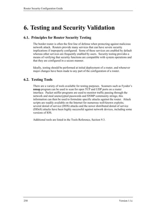
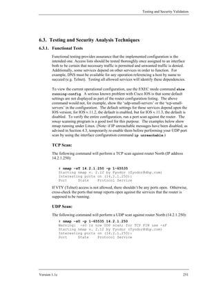
![Router Security Configuration Guide
6.3.2. Attack Tests
Attack testing can provide some assessment of the router’s robustness, i.e., how the
router will perform under the stress of an attack.
WARNING: RUNNING ATTACK SCRIPTS AGAINST AN OPERATIONAL ROUTER MAY
DEGRADE ROUTER PERFORMANCE, OR EVEN CAUSE THE ROUTER TO CRASH!
If the filters are improperly configured, or not applied to the interface, some of these
attack tests can have the same effect as a “real” attack from a malicious source.
DO NOT perform attack testing against an operational router without first considering
the possible consequences and having a recovery plan. Perform testing in a lab or
testbed environment before testing in the operational environment. When you do
perform testing on the operational network, make sure that all attack testing is
coordinated with those responsible for the network and choose a test time when the
network usage is likely to be low. DO NOT perform attack testing against any
network until you have received organizational and legal approval to do so.
Connecting to an outside network exposes the internal network and the perimeter
router to many potential risks. One of the most important security concerns is access
to the router itself. Physical security of the router should provide protection from
close-in (non-network) access. On the network, remote access must be limited using
authenticated logins or, if possible, remote logins should be disabled. To test the
remote availability, telnet to the router. The router should either refuse the request or
prompt for a password. For a more detailed discussion of Cisco router access security
and remote administration, consult Section 4.1, and the Cisco whitepaper “Improving
Security on Cisco Routers” [1].
Once access to the router has been secured, the network is still at risk of attack.
Some of the most common attacks on the internet are denial of service (DoS) attacks.
DoS attacks are typically based on high-bandwidth packet floods or other repetitive
packet streams. The easy availability and effectiveness of DoS scripts on the internet
make these attacks a favorite among hackers, particularly those without the skill to
create their own tools. For a general overview of DoS, visit the CERT site:
http://www.cert.org/tech_tips/denial_of_service.html. For more
information on the effects of DoS attacks, including recent developments and links to
specific DoS advisories, visit: http://www.cert.org/summaries/.
One popular DoS attack is the ‘smurf’ attack. This attack has at least two victims – a
target system and one or more reflector systems. The attacker sends a continuous
stream of ICMP echo requests (‘pings’) to the broadcast address of a reflector subnet.
The source address in these packets is falsified to be the address of the ultimate
target. Each packet generates a response from all hosts on the reflector subnet,
flooding the target and wasting bandwidth for both victims. The reflector networks
receiving these echo requests can block the attack at their routers by using the
interface configuration command no ip directed-broadcast (see Section 4.2).
For a detailed discussion of the smurf attack, read Craig Huegen’s paper [9].
252 Version 1.1c](https://image.slidesharecdn.com/c4-040r-02-130310054952-phpapp01/85/C4-040-r-02-252-320.jpg)
![Testing and Security Validation
Enhanced denial of service tools have recently become available on the Internet.
These distributed denial of service tools (DDoS) pose a major threat to networked
systems and have the potential to severely impact normal business activities. Unlike
a “typical” smurf attack, which uses a limited number of reflector systems, these
tools employ many compromised systems to simultaneously attack a single target.
The real attacker is able to amplify the DoS flooding while being removed from the
attacking machines; tracking the attacker is extremely difficult. There are many
such tools in circulation, four historically popular ones are called Tribal Flood
Network (TFN), Trin00, Tribal Flood Network 2000 (TFN2K) and Stacheldraht.
Cisco routers can help prevent the system behind the router from being an unwitting
participant in a DDoS attack by using the ip verify unicast reverse-path
interface command (Section 4.4.7). This feature checks each packet arriving at the
router; if the source IP address does not have a route in the CEF tables pointing back
to the same interface on which the packet arrived, the packet is dropped.
Asymmetric routing will not work with this feature, and it is only available in IOS
v12.0; similar protection can be achieved by filtering for IP spoofing, described
below. More information about DDoS attacks is available from references [3], [4],
[5], and [8].
Another common DoS attack, the SYN flood, takes advantage of the TCP three-way
handshake procedure to deny service to the victim. In a normal TCP connection
request, the requesting client sends a SYN packet to the server. The server responds
with a SYN/ACK packet, adds an entry in the connection queue and starts a timer.
The requester then completes the handshake with an ACK packet; the queue entry is
removed, the timer is reset and the connection is established. In a SYN flood, an
attacker sends a TCP connection request (SYN) packet with an unreachable, spoofed
source address to an open port on the target. The victim responds with a SYN/ACK
to the unreachable host and waits for the ACK; the ACK doesn’t arrive and the TCP
handshake never completes. The attacker continues to send these forged SYN
packets at a rapid rate until the victim’s connection queue is filled with half-open
requests. The effect of this attack is to deny TCP services such as e-mail, file transfer
or web traffic to legitimate users. Blocking access to the service under attack is
usually not feasible and would accomplish precisely what the attacker set out to do.
However, victims of a SYN flood do have some options. The host could increase the
size of the connection queue, requiring the attacker to send more phony packets to
flood the service. The host could also decrease the wait time for completion of the
three-way handshake, thus emptying the queue of half-open connections more
quickly. For more options, Cisco provides a paper titled “Defining Strategies to
Protect Against TCP SYN Denial of Service Attacks” [4].
An integral part of DoS and DDoS attacks is IP spoofing, i.e., changing the source IP
address to hide the true source of the packet. For Cisco routers running IOS v.11.2 or
11.3, filters can be used to prevent IP spoofing in a manner similar to the ip verify
unicast reverse-path feature discussed above. Access lists should check that no
packets arriving from the outside network contain a source address of either the
internal network or the well-known, non-routable, reserved addresses (defined in
RFC1918). Also, arriving packets should not have source addresses of all 0’s or all
1’s or the loopback address (127.0.0.0). Additionally, packets arriving at the router
Version 1.1c 253](https://image.slidesharecdn.com/c4-040r-02-130310054952-phpapp01/85/C4-040-r-02-253-320.jpg)
![Router Security Configuration Guide
from the internal network should not have a source address that is not one of the
legitimate internal addresses. (Note that the internal network may be using one of the
RFC1918 reserved addresses with NAT performed at the router; in this case, the
access list on the internal interface will recognize such an address as legitimate. The
goal here is to catch packets with a source address of an external network or a
reserved address that is not being used by the internal network.) This check will
prevent the internal network from being used as a launch point for a source IP
spoofing attack. To verify the anti-spoofing configuration, send a series of packets
with modified source addresses to the external interface. The packets should test the
ability of the router to detect both internal addresses and reserved addresses that
should not arrive at an external port. The router should drop these packets at the
perimeter and log the events. To verify outbound anti-spoofing, send packets to the
router’s internal interface with source addresses that are not legitimate internal
addresses; the router should again drop the packets and log the events. RFC 2267
discusses network ingress filtering and defeating DoS attacks which employ IP
source address spoofing. For an in-depth discussion of TCP flooding and IP spoofing,
consult [7].
There is a Cisco syslog vulnerability that may cause the IOS software to crash if an
invalid user datagram protocol (UDP) packet is received on the syslog port (port
514). This vulnerability affects unpatched versions of IOS 11.3AA, 11.3DB and
early (non-GD) releases of 12.0. Some vulnerable IOS devices will “hang” and must
be manually restarted by reset or power cycle; it might require an administrator to
physically visit the attacked device to restore service. At least one commonly
available vulnerability scanner can generate these UDP packets. By sending such
packets continuously, an attacker might be able to completely disable a Cisco IOS
device until the affected device is reconfigured to drop the attack traffic. This
problem can be prevented by applying the appropriate input access list to all
interfaces that might receive these packets. This input access list must block traffic
destined for UDP port 514 at any of the Cisco IOS device’s own IP addresses, as well
as at any broadcast or multicast addresses on which the device may be listening. If a
specific interface is not expected to forward legitimate syslog traffic, an alternative
fix would be to deny all syslog traffic arriving on that interface. The following
example shows an access list to block the port 514 UDP traffic.
! Deny all multicasts and all unspecified broadcasts to port 514
access-list 101 deny udp any 224.0.0.0 31.255.255.255 eq 514
! Deny old-style unspecified net broadcasts
access-list 101 deny udp any host 0.0.0.0 eq 514
! Deny network-specific broadcasts to the 14.2.0.0 net
access-list 101 deny udp any 14.2.0.255 0.0.255.0 eq 514
access-list 101 deny udp any 14.2.0.0 0.0.255.0 eq 514
! Deny packets addressed to router interface
access-list 101 deny udp any host 14.2.0.20 eq 514
! Apply to input interface of router North
interface eth0
ip access-group 101 in
254 Version 1.1c](https://image.slidesharecdn.com/c4-040r-02-130310054952-phpapp01/85/C4-040-r-02-254-320.jpg)
![Testing and Security Validation
TCP SYN packets account for a third or less of the total TCP traffic. In a SYN flood,
these SYN packets typically outnumber other TCP packets many times over. Also,
SYN floods usually contain packets with invalid source addresses; logging such
traffic (as recommended in Section 4.3) will let the administrator determine if such
source addresses are present.
There is a paper available on the Cisco web site titled “Characterizing and Tracing
Packet Floods Using Cisco Routers”. This paper gives an overview of denial of
service attacks and a detailed discussion of using access lists to categorize packets.
The paper also describes how to trace DoS attacks and the complications inherent in
packet tracing [2].
6.3.5. Attack Reaction Options
It is difficult for the ultimate target of denial of service attacks to stop or even blunt
an active attack. First, if it can be determined that the originators of the attack are
limited to a few addresses, it may be possible to apply specific filters at the external
interface of the border router. Second, if filtering is not possible, or not sufficient to
stop the attack, the only response may be to contact the reflector sites to reconfigure
their networks to shut down the attack. In a distributed attack, the ultimate target
cannot filter out the attacking addresses. In this case, the upstream provider to the
victim may be able to filter out all ICMP echo replies to the target network; this filter
should only be in place temporarily and only as a stopgap measure.
It is almost impossible to protect a network from denial of service attacks. The best
advice is to configure the router to check for IP spoofing, both inbound and
outbound, and to only allow services that are needed (see Sections 4.2 and 4.3). An
on-going problem is that new attacks can appear so fast on the internet that
countermeasures are not immediately available. Still, the only defense is to be
vigilant about security and to keep up with that latest security news by regularly
checking a site such as CERT (www.cert.org) and implementing the latest patches
from the vendors.
Version 1.1c 257](https://image.slidesharecdn.com/c4-040r-02-130310054952-phpapp01/85/C4-040-r-02-257-320.jpg)
![Testing and Security Validation
• A text file that contains IOS command to fix the problems identified in the
report. (e.g. routerconf-1.ncat_fix.txt)
RAT Example
The transcript below shows a small RAT session (version 2.1) run on Windows.
D:routeradmin> set PATH=c:CISRATbin;%PATH%
D:routeradmin> ncat_config
ncat_config: Select configuration type [cisco-ios] ? cisco-ios
ncat_config: Applying rules from:
ncat_config: c:CISRAT/etc/configs/cisco-ios/common.conf
ncat_config: c:CISRAT/etc/configs/cisco-ios/cis-level-1.conf
ncat_config: c:CISRAT/etc/configs/cisco-ios/cis-level-2.conf
ncat_config: Apply some or all of the rules that are selectable [Yes]!
ncat_config: Apply some or all of CIS level 1 rules [Yes] ? yes
ncat_config: Check rules and data related to system management
[Yes] !
ncat_config: Use local authentication [Yes] ? yes
.
.
.
ncat_config: Check rules and data related to data flow [Yes] !
ncat_config: Apply standard routing protections [Yes] ? yes
ncat_config: Forbid directed broadcasts (on IOS 11) [yes] !
ncat_config: Forbid directed broadcasts (on IOS 12) [yes] !
ncat_config: Forbid IP source routing [yes] !
ncat_config: Apply some or all of CIS Level 2 rules [No] ? no
D:routeradmin> rat northconf-2aug02
auditing northconf-2aug03...
Parsing: /c:CISRAT/etc/configs/cisco-ios/common.conf/
Parsing: /c:CISRAT/etc/configs/cisco-ios/cis-level-1.conf/
Parsing: /c:CISRAT/etc/configs/cisco-ios/cis-level-2.conf/
Parsing: /c:CISRAT/etc/configs/cisco-ios/local.conf/
Checking: northconf-2aug03
done checking northconf-2aug03.
Parsing: /c:CISRAT/etc/configs/cisco-ios/common.conf/
Parsing: /c:CISRAT/etc/configs/cisco-ios/cis-level-1.conf/
Parsing: /c:CISRAT/etc/configs/cisco-ios/cis-level-2.conf/
Parsing: /c:CISRAT/etc/configs/cisco-ios/local.conf/
ncat_report: writing northconf-2aug03.ncat_fix.txt.
ncat_report: writing northconf-2aug03.ncat_report.txt.
ncat_report: writing northconf-2aug03.html.
ncat_report: writing rules.html (cisco-ios-benchmark.html).
ncat_report: writing all.ncat_fix.txt.
ncat_report: writing all.ncat_report.txt.
ncat_report: writing all.html.
D:routeradmin>
Note that this example does not show all of the questions posed by ncat_config.
Version 1.1c 259](https://image.slidesharecdn.com/c4-040r-02-130310054952-phpapp01/85/C4-040-r-02-259-320.jpg)

![Testing and Security Validation
6.5. References
Web Sites and On-Line Resources
[1] “Improving Security on Cisco Routers”, Cisco Technical Tips,
Cisco Systems, 2002.
available at: http://www.cisco.com/warp/public/707/21.html
A good summary of basic IOS router security practices; also includes a
reference to the Cisco IOS Output Interpreter, a web-based tool that
registered Cisco customers can use for a cursory security analysis of their
IOS configurations.
[2] “Characterizing and Tracing Packet Floods Using Cisco Routers”,
Cisco Technical Tips, Cisco Systems, 2000.
available at: http://www.cisco.com/warp/public/707/22.html
Detailed guidance on tracing certain kinds of DoS attacks.
[3] “Strategies to Protect Against Distributed Denial of Service (DDoS) Attacks”,
Cisco White Papers, Cisco Systems, 2000.
available at: http://www.cisco.com/warp/public/707/newsflash.html
[4] “Defining Strategies to Protect Against TCP SYN Denial of Service Attacks”,
Cisco White Papers, Cisco Systems, 1999.
available at: http://www.cisco.com/warp/public/707/4.html
[5] “Denial of Service Attacks”, CERT Coordination Center, Software Engineering
Institute, 1997.
available at: http://www.cert.org/tech_tips/denial_of_service.html
A good overview of DoS attack principles.
[6] “Distributed Denial of Service Tools”, CERT Incident Note IN-99-07, CERT
Coordination Center, Software Engineering Institute, 1999.
available at: http://www.cert.org/incident_notes/IN-99-07.html
[7] “Topic: TCP SYN Flooding and IP Spoofing Attacks”, CERT Advisory
CA96.21, CERT Coordination Center, Software Engineering Institute, 1996.
available at: http://www.cert.org/advisories/CA-1996-21.html
[8] “Distributed Attack Tools”, Packet Storm, Securify Inc, 2000.
available at: http://packetstormsecurity.nl/distributed/
[9] Huegens, C. “The Latest in Denial of Service Attacks: Smurfing”, 2000.
available at: http://www.governmentsecurity.org/archive/t1497.html
Version 1.1c 261](https://image.slidesharecdn.com/c4-040r-02-130310054952-phpapp01/85/C4-040-r-02-261-320.jpg)
![Router Security Configuration Guide
[10] Wolfgang, M. “Exploiting Cisco Routers (Part One)”, 2003.
available from: http://www.securityfocus.com/infocus/1734
Additional Exploit-Related Pages:
http://packetstormsecurity.nl/exploits/DoS
http://packetstormsecurity.nl/spoof/
Additional General Exploit Information Sites:
http://www.hackers.com/
http://www.securityfocus.com/
Automated security scanning and testing tool sites:
RAT -
http://www.cisecurity.org/bench_cisco.html
ISS Internet Scanner -
http://www.iss.net/find_products/vulnerability_assessment.php
SAINT -
http://www.saintcorporation.com/products/saint_engine.html
SATAN - http://www.porcupine.org/satan
NESSUS - http://www.nessus.org/
262 Version 1.1c](https://image.slidesharecdn.com/c4-040r-02-130310054952-phpapp01/85/C4-040-r-02-262-320.jpg)
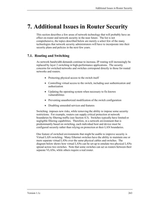
![Additional Issues in Router Security
7.2. IPv6
The Internet was built using version 4 of the Internet protocol (IPv4). In the mid-
1990s, it became clear that the Internet would eventually outgrow the address space
and capabilities of IPv4, and the IETF initiated efforts to standardize a successor. IP
version 6 (IPv6) was first standardized in 1995, and the standard revised to its current
form in 1998.
The Internet community is gradually migrating from IPv4 to v6. The US government
and US DOD have set ambitious goals to complete substantial migration by 2008.
By mid-2005, hundreds of IPv6 address blocks had already been allocated to network
carriers and enterprises all over the world. During the transition period, it is expected
that many routers will have to support both IPv4 and IPv6 (so-called “dual stack”
operation) as well as supporting transition mechanisms like encapsulation and
translation.
The table below gives a few comparisons between IPv4 and IPv6.
Property IPv4 IPv6
Address size 32 bits 128 bits
Network mask size varies, 8-30 bits usually fixed, 64 bits
Packet header size 20-60 bytes 40 bytes (fixed)
Packet-level extensions limited number of small unlimited number of
IP options IPv6 extension headers
Fragmentation sender or any intermediate only sender may
router allowed to fragment fragment
Control protocols mixture of non-IP (ARP), all control protocols
ICMP, and other protocols based on ICMPv6
Minimum allowed MTU 576 bytes 1280 bytes
Path MTU discovery optional, not widely used mandatory
Cisco IOS routers support IPv6 in IOS versions 12.2T, 12.3, and later. Security best
practices for IPv6 are not yet well-established, although some recommendations exist
(see [15]). Defining best practices and configuration guidelines for routers handling
IPv4 and IPv6 may be complicated, due use of transition mechanisms and
interactions between IPv4 and IPv6 features.
For more information, consult any good book on IPv6, such as [16]. At the time of
this writing, an IPv6 supplement to this guide is in preparation, and should be
published by mid-2006. The supplement will be available from www.nsa.gov/ia.
Version 1.1c 265](https://image.slidesharecdn.com/c4-040r-02-130310054952-phpapp01/85/C4-040-r-02-265-320.jpg)
![Router Security Configuration Guide
7.5. IPSec and Dynamic Virtual Private Networks
Section 5.2 explains some of the basic features of IPSec. However, IPSec and
Virtual Private Network (VPN) configuration are complex topics. As deployment of
VPNs becomes more common, the simple configurations described in Section 5.2
probably will not scale well enough to satisfy users’ needs. To achieve scalability,
VPNs will need to be dynamic, employing public keys and public key certificates to
set up IPSec-protected links on the fly
Security configuration issues are likely to be important in deployment of large
dynamic VPNs are listed below.
• PKI enrollment and obtaining certificates –
To participate in a dynamic VPN based on Public Key Infrastructure
(PKI), a router or any other device must possess a copy of the correct root
and authority certificates, and it must have its own certified public key and
private key. Installing certificates and setting up authorities on Cisco
routers is complex but well-documented. There are also trust issues in any
large VPN deployment: are all members of the VPN trusted equally? In
general, IPSec is most useful for integrity and confidentiality assurance,
but not for authorization or access control.
• Certificate revocation –
In any large-scale PKI, removing certified principals from the trusted
community is very important. PKI standards define various data formats
and protocols for defining revocations and for checking certification status,
including X.509 Certificate Revocation Lists (CRLs) and the Online
Certificate Status Protocol (OCSP). It may be necessary to configure
revocation checking on routers participating in dynamic VPNs.
• Cryptographic issues –
Selection of uniform key sizes and cryptographic algorithms will be a
contentious issue in VPN deployment. Cisco routers currently support
only a small complement of algorithms, depending on the installed IOS
version and feature set.
• Designating traffic to be encrypted –
Cisco routers, and most other VPN systems, support the ability to protect
certain traffic based on its protocol and port numbers. Currently, there are
no uniform guidelines for selecting traffic to protect.
For complete information on the IPSec and dynamic VPN capabilities of Cisco IOS
12.0, consult Cisco IOS 12.0 Network Security [2].
268 Version 1.1c](https://image.slidesharecdn.com/c4-040r-02-130310054952-phpapp01/85/C4-040-r-02-268-320.jpg)
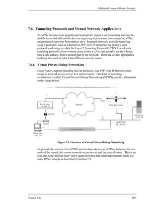
![Router Security Configuration Guide
7.9. References
[1] Sacket, G.C. Cisco Router Handbook, McGraw-Hill, New York, NY, 2000.
Contains a good overview of Cisco ATM facilities.
[2] Cisco IOS 12.0 Network Security, Cisco Press, Indianapolis, IN, 1999.
Authoritative source for in-depth descriptions of security-related IOS
facilities, including IPSec and related configuration commands.
[3] Cisco IOS 12.0 Switching Services, Cisco Press, Indianapolis, IN, 1999.
This documentation volume includes extensive configuration information for
Cisco ATM switching and LANE.
[4] Doraswamy, N. and Harkins, D. IPSec: The New Security Standard for the
Internet, Intranets, and Virtual Private Networks, Prentice-Hall, Upper Saddle
River, NJ, 1999.
Contains a good overview and substantial technical detail about IPSec and
related topics.
[5] Kent, S. and Atkinson, R. “Security Architecture for the Internet Protocol,” RFC
2401, 1998.
The master document for IPSec, includes extensive remarks about VPN
architecture.
[6] Eastlake, D. “Domain Name System Security Extensions,” RFC 2535, 1999.
The updated standard for secure DNS, includes extensive discussion and
examples.
[7] Braden, Z,, Berson, H., and Jamin, “Resource reSerVation Protocol (RSVP) –
Version 1 Functional Specification,” RFC 2205, 1997.
The basic standard for RSVP, defines the protocol structure and intent.
[8] Baker, Lindell, and Talwar, RFC 2747, “RSVP Cryptographic Authentication”,
2000.
Describes the message authentication service to be used with RSVP.
[9] Laubach, M. and Halpern, J. “Classical IP and ARP over ATM”, RFC 2225,
1998.
The definition of Classical IP over ATM; also good background reading for
understanding the issues of hosting IP over ATM.
272 Version 1.1c](https://image.slidesharecdn.com/c4-040r-02-130310054952-phpapp01/85/C4-040-r-02-272-320.jpg)
![Additional Issues in Router Security
[10] Townsley, V., Rubens, P., Zorn, P., “Layer Two Tunneling Protocol (L2TP),”
RFC 2661, 1999.
Definition of the Internet standard tunneling protocol, including discussion of
the relationships of IP, PPP, and L2TP.
[11] Black, U., PPP and L2TP, Prentice-Hall, 2000.
A very detailed overview of remote access and layer 2 tunneling, including
some coverage of security options.
[12] Shea, R., L2TP Implementation and Operation, Addison-Wesley, 2000.
An in-depth treatment of L2TP itself, with some analysis of its security.
[13] Cisco System, “MPLS/Tag Switching”, Internetworking Technologies
Handbook, 2002.
available at: http://www.cisco.com/univercd/cc/td/doc/cisintwk/
ito_doc/mpls_tsw.pdf
A short paper offering an overview of MPLS and a comparison with
traditional routing.
[14] Guichard, Jim and Pepelnjak, Ivan., MPLS and VPN Architectures: A practical
guide to understanding, designing and deploying MPLS and MPLS-enable
VPNs, Cisco Press, 2001.
A highly detailed guide to setting up MPLS networks.
[15] Convery, S. and Miller, D., “IPv6 and IPv4 Threat Comparison and Best-
Practice Evaluation”, version 1.0, Cisco Systems, March 2004.
available at: http://www.cisco.com/security_services/ciag/
documents/v6-v4-threats.pdf
A seminal analysis of network risks posed by IPv6, and comparison with
risks posed by IPv4. It also includes some security guidance for configuring
Cisco routers.
[16] Desmeules, R., Cisco Self-Study: Implementing Cisco IPv6 Networks, Cisco
Press, 2003.
A very detailed overview of IPv6, written from a network-oriented
viewpoint. Provides detailed instructions for configuring IPv6 functionality
on Cisco routers
Version 1.1c 273](https://image.slidesharecdn.com/c4-040r-02-130310054952-phpapp01/85/C4-040-r-02-273-320.jpg)
![Router Security Configuration Guide
8. Appendices
The sections below offer ancillary material and supplemental guidance for network
and security administrators.
8.1. Top Ways to Quickly Improve the Security of a Cisco Router
This appendix describes the most important and effective ways to tighten the security
of a Cisco router, along with some important general principles for maintaining good
router security. The descriptions here are terse, for more details consult the
corresponding parts of Section 4. References to appropriate parts of Section 4 appear
at the end of each recommendation.
General Recommendations
Comment and organize offline editions of each router configuration file! This sounds
fluffy despite being a big security win. Keep the offline copy of each router
configuration in sync with the actual configuration running on the router, and keep all
it and all old versions under configuration management. This is invaluable for
diagnosing suspected attacks or problems and recovering from them. [Section 4.1]
Implement access list filters by permitting only those protocols and services that the
network users really need, and explicitly denying everything else. Trying to deny just
the ‘bad things’ is a losing proposition. [Section 4.3]
Run the latest available General Deployment (GD) IOS version. [Sections 4.5.5, 8.3]
Specific Recommendations
1. Shut down unneeded services - things that aren’t running can’t break,
and save memory and processor slots too. Start by running the show
proc command on the router, then turn off clearly unneeded facilities
and services. Some services that should almost always be turned off are
listed below.
• CDP - Cisco Discovery Protocol is used almost exclusively by
Cisco RMON; CDP sends packets from your router once a minute
or so identifying your router. Use the no cdp run command to
kill the process and disable CDP globally. To leave CDP running
but disable it for certain network connections, apply the command
no cdp enable to the appropriate interfaces. [Section 4.2]
• Small services - miscellaneous UDP (echo, discard, chargen) and
TCP (echo, discard, chargen, daytime) based services. One of
these is the UDP echo which is used in the ‘fraggle’ attack. Use
the commands no service udp-small-servers and no
service tcp-small-servers to turn these off. [Section 4.2]
274 Version 1.1c](https://image.slidesharecdn.com/c4-040r-02-130310054952-phpapp01/85/C4-040-r-02-274-320.jpg)
![Appendices
• Finger - the finger daemon. Use the command no service
finger (IOS 11.2 and earlier) or no ip finger (IOS 11.3 and
later). [Section 4.2]
• NTP - the Network Time Protocol. If NTP is not being employed
for time synchronization, turn it off with no ntp server. NTP
can also be disabled for only a specific interface with the ntp
disable command. [Sections 4.2, 4.5]
• BOOTP – the IP bootp server. Turn off this little-used server with
the command no ip bootp server. [Section 4.2]
2. Don't be a Smurf buddy! While the Smurf attack doesn't usually attack
the router itself, a Smurf attack can let an attacker use your network to
launch denial of service raids on other sites; the attacks will appear to
come from you. To prevent this, use the command no ip directed-
broadcast on all interfaces. This may be the default on some recent
versions of IOS, but include it in your configuration explicitly anyway.
[Section 4.2]
Central(config)# interface eth 0/0
Central(config-if)# no ip directed-broadcast
3. Shut down unused interfaces using the shutdown command. Check
them with the show ip interface brief command. If the router has
an auxiliary console port (aux port) and it is not in use, shut it down as
shown below. [Section 4.1]
Central(config)# interface eth 0/3
Central(config-if)# shutdown
Central(config-if)# exit
Central(config)# line aux 0
Central(config-line)# no exec
Central(config-line)# transport input none
Central(config-line)# exit
4. Always start an access-list definition with the command no access-
list nnn to make sure it starts out clean. [Section 4.3]
East(config)# no access-list 51
East(config)# access-list 51 permit host 14.2.9.6
East(config)# access-list 51 deny any log
5. Log access list port messages properly. For reasons of efficiency, Cisco
IOS doesn't look at an entire packet header unless it has to. If packets are
rejected by an access list filter for other reasons, the log message will
often list the packet as using “port 0”. To prevent this from happening,
instead of the usual logging access list command (such as access-list
106 deny ip any any log), use the special port range arguments
shown below.
no access-list 106
access-list 106 deny udp any range 0 65535 any range 0 65535 log
Version 1.1c 275](https://image.slidesharecdn.com/c4-040r-02-130310054952-phpapp01/85/C4-040-r-02-275-320.jpg)
![Router Security Configuration Guide
access-list 106 deny tcp any range 0 65535 any range 0 65535 log
access-list 106 deny ip any any log
The last line is necessary to ensure that rejected packets of protocols
other than TCP and UDP are properly logged. [Section 4.3]
6. Password and access protect the Telnet VTYs. By default, virtual
terminals (telnet) are unprotected. To set a password, use the password
command. To control access, use an access list and the access-class
command. If only specific methods of attaching to the VTY, such as
Telnet or SSH, are permitted, use the transport input command to
enable only those methods. [Section 4.1]
South(config)# line vty 0 4
South(config-line)# login
South(config-line)# password Soda-4-J1MMY
South(config-line)# access-class 2 in
South(config-line)# transport input telnet
South(config-line)# exit
South(config)# no access-list 92
South(config)# access-list 92 permit 14.2.10.0 0.0.0.255
Controlling authentication for login to the router is an extremely
important topic, consult Sections 4.1 and 4.6 for guidance.
7. Unless the network is one of those very rare setups that needs to allow
source routed packets, the source routing facility should be disabled with
the command no ip source-route. [Section 4.2]
Central(config)# no ip source-route
8. Turn off SNMP trap authentication to prevent a remote SNMP system
shutdown request. In IOS 11.2 and later use the global configuration
command no snmp-server enable traps. If SNMP is not being
used on the router, turn it off with the command no snmp-server.
[Sections 4.2, 4.5.3]
South(config)# no snmp-server enable traps
South(config)# no snmp-server
9. Make sure that the router enable password is encrypted using the strong
MD5-based algorithm by using the enable secret command rather
than the enable password command. [Section 4.1]
South(config)# enable secret 2Many-Routes-4-U
South(config)#
10. Allow only internal addresses to enter the router from the internal
interfaces, enforce this using access lists. Block illegal addresses at the
outgoing interfaces. Besides preventing an attacker from using the router
to attack other sites, it helps identify mis-configured internal hosts and
276 Version 1.1c](https://image.slidesharecdn.com/c4-040r-02-130310054952-phpapp01/85/C4-040-r-02-276-320.jpg)
![Appendices
networks. This approach may not be feasible for very complicated
networks. [Section 4.3]
East(config)# no access-list 101
East(config)# access-list 101 permit ip 14.2.6.0 0.0.0.255 any
East(config)# access-list 101 deny udp any range 1 65535 any log
East(config)# access-list 101 deny tcp any range 1 65535 any log
East(config)# access-list 101 deny ip any any log
East(config)# interface eth 1
East(config-if)# ip access-group 101 in
East(config-if)# exit
East(config)# interface eth 0
East(config-if)# ip access-group 101 out
East(config-if)# end
11. Turn on the router’s logging capability, and use it to log errors and
blocked packets to an internal (trusted) syslog host. Make sure that the
router blocks syslog traffic from untrusted networks. [Section 4.5]
Central(config)# logging buffered
Central(config)# logging trap info
Central(config)# logging facility local1
Central(config)# logging 14.2.9.6
12. Block packets coming from the outside (untrusted network) that are
obviously fake or are commonly used for attacks. This protection should
be part of the overall design for traffic filtering at the router interface
attached to the external, untrusted network. [Section 4.3]
• Block packets that claim to have a source address of any internal
(trusted) networks. This impedes some TCP sequence number
guessing attacks and related attacks. Incorporate this protection
into the access lists applied to interfaces connected to any
untrusted networks.
• Block incoming loopback packets (address 127.0.0.1). These
packets cannot be real.
• If the network does not need IP multicast then block it.
• Block broadcast packets. (Note that this may block DHCP and
BOOTP services, but these services should not be used on
external interfaces.)
• A number of remote attacks use ICMP redirects, block them. (A
superior but more difficult approach is to permit only necessary
ICMP packet types.)
The example below shows how to enforce these rules on router North.
North(config)# no access-list 107
North(config)# ! block internal addresses coming from outside
North(config)# access-list 107 deny ip 14.2.0.0 0.0.255.255 any log
North(config)# access-list 107 deny ip 14.1.0.0 0.0.255.255 any log
North(config)# ! block bogus loopback addresses
North(config)# access-list 107 deny ip 127.0.0.1 0.0.0.255 any log
Version 1.1c 277](https://image.slidesharecdn.com/c4-040r-02-130310054952-phpapp01/85/C4-040-r-02-277-320.jpg)
![Router Security Configuration Guide
North(config)# ! block multicast
North(config)# access-list 107 deny ip 224.0.0.0 0.0.255.255 any
North(config)# ! block broadcast
North(config)# access-list 107 deny ip host 0.0.0.0 any log
North(config)# ! block ICMP redirects
North(config)# access-list 107 deny icmp any any redirect log
.
.
North(config)# interface eth 0/0
North(config-if)# ip access-group 107 in
13. Block incoming packets that claim to have the same destination and
source address (i.e. a ‘Land’ attack on the router itself). Incorporate this
protection into the access list used to restrict incoming traffic into each
interface, using a rule like the one shown below (part of the
configuration file for router East). [Section 4.3]
no access-list 102
access-list 102 deny ip host 14.2.6.250
host 14.2.6.250 log
access-list 102 permit ip any any
interface Eth 0/0
ip address 14.2.6.250 255.255.255.0
ip access-group 102 in
14. Turn on TCP keepalive packets for administrative telnet sessions, using
the command service tcp-keepalives-in. [Section 4.1]
15. Proxy ARP is used to set up routes on the fly for internal hosts or subnets
and may reveal internal addresses. Disable it by applying the command
no proxy-arp to each external interface. If proxy ARP is not needed,
disable it on all interfaces. [Section 4.2]
Central(config)# interface eth 0/0
Central(config-if)# no proxy-arp
16. Except on the rarely-seen Cisco 1000 series routers, the HTTP server is
off by default. To be safe, however, include the command no ip
http server in all router configurations. [Section 4.2]
17. So that the complete date and time are stamped onto entries in the routers
buffered log, use the global configuration command service
timestamps as shown in the example below. [Section 4.5]
East(config)# service timestamps log date
msec local show-timezone
East(config)#
18. Unless the router absolutely needs to autoload its startup configuration
from a TFTP host, disable network autoloading with the command no
service config. [Section 4.2]
278 Version 1.1c](https://image.slidesharecdn.com/c4-040r-02-130310054952-phpapp01/85/C4-040-r-02-278-320.jpg)
![Appendices
19. Turn on password encryption, so that regular passwords are stored and
displayed in scrambled form. This provides some security against casual
‘over-the-shoulder’ attacks. [Section 4.1]
East(config)# service password-encryption
20. Update your IOS image to the latest General Deployment (GD) release.
It is not necessary to install each and every new IOS release, but it is a
good idea to keep your router up to date. In general, newer releases will
include fixes for security bugs, and will provide new security features.
Installing an update normally imposes some downtime, so plan your
updates carefully. [Section 4.5]
For more information about testing router security, and defending against common
attacks, see Section 6.
Version 1.1c 279](https://image.slidesharecdn.com/c4-040r-02-130310054952-phpapp01/85/C4-040-r-02-279-320.jpg)
![Router Security Configuration Guide
8.2. Application to Ethernet Switches and Related Non-Router
Network Hardware
This appendix identifies specific topical areas and recommendations from the main
body of this guide that apply to Ethernet switches, managed hubs, access servers, and
other network hardware components that are not IP routers. Prior to the 1990s,
routers were the only LAN components with sufficient flexibility to need security
configuration. Since the mid-1990s, hubs, switches, access servers, and other LAN
components have acquired substantial capabilities; many of them are as flexible and
configurable as a router. Such devices almost always support remote administration
and management, and are therefore subject to compromise over the network.
Because they are vital to network operations and because they can be used as a
staging area for additional attacks, it is important to configure them securely.
The discussion below focuses mainly on media-level network components: switches,
managed hubs, and bridges. These devices are characterized by participation in the
network itself by forwarding and switching traffic based on a media layer address
(e.g. an Ethernet MAC address). Because they cannot perform network layer or
transport layer traffic filtering, switches and hubs cannot generally enforce security
policies on network traffic. The focus for security for these devices is protecting
their own configuration, and preventing their use by unauthorized individuals and
attackers.
The NSA “Cisco IOS Switch Security Configuration Guide” [2] provides a great deal
more information on the secure configuration of Cisco Ethernet switches. It can be
downloaded from http://www.nsa.gov/ia.
8.2.1. Security Principles and Goals
The general security goals for a switch or smart hub are similar to those for a router,
but simpler because such a network component does not act as a boundary device
between different networks. The security goals for a switch or hub are listed below.
• preventing unauthorized examination of device state and configuration
• preventing unauthorized changes to the device state and configuration
• preventing use of the device for attacking the local network
• preventing unauthorized remote management/monitoring of the device
To achieve these goals, the device must be configured to strictly limit all forms of
access: physical, local connections, and remote network connections. If possible, it is
best to create a security checklist for LAN switches. Follow the general form of the
security checklist given at the end of Section 3. More information is available in [4].
280 Version 1.1c](https://image.slidesharecdn.com/c4-040r-02-130310054952-phpapp01/85/C4-040-r-02-280-320.jpg)
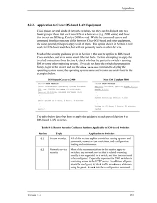
![Router Security Configuration Guide
Section Topic Application to Switches
4.3 Access lists IOS-based switches support IP access lists, but do not use
them for as many different purposes as a router does.
Basically, on a switch, access lists are used for limiting
access to services on the switch itself, but not for filtering
traffic passing through the switch.
4.4 Routing This section is not usually applicable to switches, although
protocols some Cisco switches can act as routers, too.
[Note: some Catalyst 5000 and higher series switches are
equipped with a ‘Route Switch Module’. This module is
essentially a 4700-series IOS router attached to the switch.
It should be configured using Section 4 like any other
router.]
4.5 Audit and Almost all of this section applies to IOS-based switches;
Management some switch IOS versions do not support NTP, and must
have their time set manually. All switches support RMON
and SNMP; these services should be disabled if not in use,
or access to them should be restricted.
4.6 Access control All of this section is applicable to IOS-based switches, if
with AAA they support AAA (IOS 11.2 and later).
Note that Cisco switch-resident routing hardware (e.g. Catalyst 5000 series Route
Switch Modules) can and should be configured using the guidance in Section 4, after
careful consideration of its role in the network security policy.
Most of the security testing guidance given in Section 6 also applies to LAN
switches. Consult [2] for more detailed guidance and specific examples.
8.2.3. References
[1] Turner, A., “Network Insecurity with Switches”, GIAC Paper, December 2000.
available at: http://www.synfin.net/papers/switch_security.pdf
An examination of the security (and lack of it) provided by separating traffic
with Ethernet switches; includes several good references. Many of the issues
discussed in the paper have since been fixed, but the discussion is still
valuable.
[2] Borza, Duesterhaus, et al. “Cisco IOS Switch Configuration Guide”, NSA, June
2004.
available under: http://www.nsa.gov/ia/
This highly detailed guide covers general switch security, VLAN
configuration, port management, and more.
282 Version 1.1c](https://image.slidesharecdn.com/c4-040r-02-130310054952-phpapp01/85/C4-040-r-02-282-320.jpg)
![Appendices
8.3. Overview of Cisco IOS Versions and Releases
Cisco provides a very large number of software releases for their routers and other
products. This appendix provides an overview of the major release levels, and the
release naming scheme. It is intended to help with upgrade strategies and version
selection. In general, operational routers should kept up to date with the newest
stable release that provides all the needed features. Often it will not be practical to
install all the updates that Cisco makes available, especially during the flurry of bug
fix releases that tends to follow a major change. Devise a consistent upgrade strategy
that matches the needs of your network, and then follow it; use this appendix and the
materials listed in the references, to understand what Cisco provides.
8.3.1. Release Levels and Names
Cisco follows strict naming schemes for IOS releases. Unfortunately, the format has
changed several times since IOS was first introduced in the mid-1990s. The current
format for a Cisco IOS release name is shown below.
VV.N.M RR Examples:
Release identifier 12.0.3 Release = 12.0
Revision = 3
Maintenance revision number
11.3.5T Release = 11.3
Minor release number
Revision = 5
IOS Major release Identifier = T
number: 10, 11, 12
Figure 8-1 – Cisco IOS Release Naming
In general, release number and release identifiers tell what features could be
available, and the revision number tells how many times the release has undergone
fixes to correct problems. Cisco releases may be broadly divided into kinds: regular
shipping releases (general or limited) and early releases. A regular release will
almost always have a simple number with no release identifier, such as 12.0.8. An
early release will usually include an identifier, and may also include a number in
parentheses. For example, the release “12.1.3T” is IOS version 12.1, revision 3,
identifier T. The ‘T’ identifier designates an early release of new technology
features. For operational purposes, it is usually best to avoid early release software,
unless it has some required, critical feature. There is a complex naming scheme for
early releases that is beyond the scope of this guide; consult [1] for complete details.
Some of the suffixes that you might see on special-purpose releases include “XA”,
“HA”, “F”. You might also see maintenance revision numbers in parentheses,
usually for ED releases; for example, 11.2(9)XA.
Version 1.1c 283](https://image.slidesharecdn.com/c4-040r-02-130310054952-phpapp01/85/C4-040-r-02-283-320.jpg)
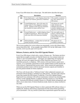
![Glossary
which you hope to run the software. Ensure that amounts of installed memory meet
or exceed the requirements before attempting to load the IOS release.
Cisco also offers a hardware/software compatibility matrix checker, freely available
on their web site. Using this tool [3], you can check what IOS releases are supported
on your router model.
8.3.2. Major Releases and their Features
There are at least five major releases of Cisco IOS software currently in use in
operational environments: 11.3, 12.0, 12.1, 12.2, and 12.3. The lists below describe
some of the major features introduced into IOS in each of these releases, with
emphasis on security-relevant features.
All earlier Cisco IOS releases, 11.2, 11.1, and earlier, are now mostly unsupported by
Cisco, although some of them are still available for download.
IOS 11.1
The 11.1 release was the last IOS release to use the old ‘classic’ or monolithic
architecture. While exceedingly stable and robust, it did not offer extensive security
features. IOS 11.1 was first deployed in 1996, and engineering development for it
was dropped in 1999. Some of the important features
• RIPv2 (see Section 4.5)
• The IOS web server and web browser management interface
[IOS 11.1(5) and later]
• RADIUS support (as part of AAA, see Section 4.6)
• RMON support (see Section 4.5)
• Lock-and-Key dynamic access lists
IOS 11.1 is available as a GD release for all older Cisco routers, but is not available
for some of the popular newer models (e.g. 7500, 1605, 3660).
IOS 11.2
The 11.2 release was the first IOS version to fully implement Cisco’s modular
architecture for router software. A great many new features were added to IOS over
the lifetime of 11.2, a few of them are listed below.
• Named access control lists (See Section 4.3)
• Network address translation (NAT)
• Support for RSVP and IP Quality-of-Service (see Section 7.5)
• Various OSPF and BGP4 enhancements
Version 1.1c 285](https://image.slidesharecdn.com/c4-040r-02-130310054952-phpapp01/85/C4-040-r-02-285-320.jpg)
![Glossary
• SNMP version 3 (See Section 4.6)
• Time-based access lists
• General availability of IP unicast reverse-path verification [Section 4.4]
IOS 12.0 is available in both LD and GD forms for almost all supported Cisco router
platforms, and many other Cisco hardware products.
IOS 12.1
The 12.1 release is an incremental step forward from 12.0. As of the summer of
2003, it was the latest release available at GD status for some devices. Some of the
security features that appeared in 12.1 are listed below.
• Enhanced IPSec certificate management and AAA integration
• AAA enhancements: server groups, more accounting features
• Unicast reverse path forwarding security enhancements
• Initial broad support for Secure Shell (SSH Version 1) server
IOS 12.2
The 12.2 release adds some new features to 12.1, as well as enhancements to some
core security features. IOS 12.2 reached GD status in 2002. A few of the many
enhancements in 12.2 are listed below.
• Improved support for IP Quality-of-Service and RSVP
• Multi-Protocol Label Switching (MPLS) support
• Enhancements to SSH support
• Enhancements to IPSec and IKE
• Turbo Access Lists (some router models)
• Better application of service password-encryption
IOS 12.3
The 12.3 release added several substantial new security features, and also expanded
the availability of some features. As of summer 2005, IOS 12.3 had not yet reached
GD status. Some of the security updates in 12.3 are listed below.
• Secure Shell Version 1.5 (SSHv1) supported in nearly all IOS editions
• Cisco Auto Secure feature added, simplifies basic secure configuration
• New features added for password and authentication controls
Version 1.1c 287](https://image.slidesharecdn.com/c4-040r-02-130310054952-phpapp01/85/C4-040-r-02-287-320.jpg)
![Router Security Configuration Guide
• SSL support added for the IOS web server (some IOS editions)
• Improvements in PKI and firewall support
• Introduced Control Plane Policing (some IOS editions)
IOS 12.4
The 12.4 release adds additional security features and many new protocols and
functions to IOS. A few of the new security features are listed below.
• Secure Shell Version 2 (SSHv2) supported, client and server.
• Improvements to protocol inspection for the IOS firewall
• Control plane traffic policing (some IOS editions)
• Many improvements to PKI and certificate support
• Added login password control features: retry delay, retry lockout
Finding Features in IOS Releases
Cisco’s web site offers a useful service called the ‘Feature Navigator’ that supports
searching for features by name or release number. The service is available to
registered customers at http://tools.cisco.com/ITDIT/CFN/jsp/index.jsp.
8.3.3. References
[1] Coulibaly, M.M., Cisco IOS Releases: The Complete Reference, Cisco Press,
2000.
This highly specialized book covers the Cisco IOS release system and release
history in painstaking detail. However, it only covers up through IOS 12.0.
[2] “Cisco IOS Reference Guide”, Cisco White Papers, Cisco Systems, 2004.
available at: http://www.cisco.com/warp/public/620/1.html
This detailed web page explains the IOS release naming scheme, decribes
features in IOS 12.3, and includes a map of releases up through 12.2.
[3] “Hardware/Software Compatibility Matrix”, part of the Cisco Software Advisor,
Cisco Systems, 2001.
available at:
http://www.cisco.com/pcgi-bin/front.x/Support/HWSWmatrix/hwswmatrix.cgi
This interactive web page allows you to find IOS releases compatible with
particular router models. (Note: may be available to registered users only.)
[4] Bollapragada, V., Murphy, C., White, R., Inside IOS Software Architecture,
CCIE Professional Development Series, Cisco Press, 2000.
A very detailed examination of IOS, focused on packet handling and routing.
288 Version 1.1c](https://image.slidesharecdn.com/c4-040r-02-130310054952-phpapp01/85/C4-040-r-02-288-320.jpg)
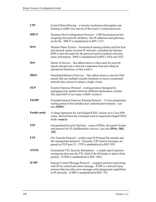
![Glossary
IETF Internet Engineering Task Force – the technical and consultative
body that defines standards for the Internet. IETF standards are
published by RFC number, the list of current standards (STD 1) is
RFC 3700.
IGP Interior Gateway Protocol – a routing protocol used among the
routers in an autonomous system. Currently popular IGPs include
OSPF, RIP, EIGRP, and IS-IS.
IKE Internet Key Exchange – the standard security negotiation and key
management protocol used with IPSec. IKE is standardized in RFC
2409.
IOS Internet Operating System – Cisco’s name for the modular software
system that runs on their routers and many other network devices.
IP Internet Protocol version 4 – The network-layer protocol on which
the Internet is built. There are two extant versions of IP: IPv4 and
IPv6. IPv4 is standardized in RFCs 791 and 1883. [Note: this
guide covers security only for IPv4.]
IPv6 Internet Protocol version 6 – The new network-layer protocol for
the future of the Internet. I is standardized in RFC 2460. [Note:
security recommendations for IPv6 will be provided in a separate
supplement to this guide.]
IPSec Internet Protocol Security – a set of standards that define
confidentiality and integrity protection for IP traffic. IPSec is
standardized by a set of RFCs including RFC 2401.
IS-IS Intermediate System to Intermediate System – an OSI standard
interior gateway protocol based on a link state model. IS-IS is
standardized in ISO-10589 and RFC 1195.
ISAKMP Internet Security Association Key Management Protocol – one of
the precursors of IKE (see also IKE, IPSec).
Kerberos Kerberos was developed by the Massachusetts Institute of
Technology as a network authentication system, and it provides
strong authentication for client/server applications by using secret-
key cryptography. Kerberos is standardized in RFC 1510 (see also
RADIUS and TACACS+).
LAN Local Area Network – general term for a single-segment or
switched network of limited physical/organizational extent.
LANE LAN Emulation – A standard mechanism for routing IP packets
over ATM.
Version 1.1c 291](https://image.slidesharecdn.com/c4-040r-02-130310054952-phpapp01/85/C4-040-r-02-291-320.jpg)