SlideShare a Scribd company logo
1 of 23
PRESENTED BY:-
MOUNIKA .G
SUYESH .V
1. INTRODUCTION
2. Basic construction and operation
3. TYPES OF LOCK LIFT
1. STAIR CASE LOCK LIFT
2. DROP LOCK
3. FLOOD LOOK AND FLOOD GATES
4. TYPES OF FLOOD GATES
5. TIDAL LOCK
6. HIRAM M.
4. INCLINED PLANE
5. MARINE RAILWAY LOCK
6. BOAT LIFT
7. CAISSON LOCKS
8. Use Of Lock In River Navigation
9. CONCLUSION
10. REFERENCE
CONTEXT
INTRODUCTION
 A lock is a device used for raising and
lowering Boats, ships and
other watercraft between stretches of water of
different levels on river and canal waterways. The
distinguishing feature of a lock is a fixed chamber
in which the water level can be varied ,
 where as in a caisson lock, a boat lift, or on
a Canal inclined plane it is the chamber itself
(usually then called a caisson ) that rises and
falls.
 Locks are used to make a river more easily
navigable, or to allow a canal to take a reasonably
direct line across land that is not level.
Basic construction and operation
• Construction
•A watertight chamber connecting the upper and lower canals, and large enough
to enclose one or more boats. The position of the chamber is fixed, but its water
level can vary.
• A gate (often a pair of "pointing" half-gates) at each end of the chamber. A gate
is opened to allow a boat to enter or leave the chamber; when closed, the gate is
watertight.
• A set of lock gear to empty or fill the chamber as required. This is usually a
simple valve which allows water to drain into or out of the chamber larger locks
may use pumps.
•Operation
• The principle of operating a lock is simple. For instance, if a boat travelling
downstream finds the lock already full of water:
• The entrance gates are opened and the boat moves in.
• The entrance gates are closed.
• A valve is opened, this lowers the boat by draining water from the chamber.
The exit gates are opened and the boat moves out
• If the lock were empty, the boat would have
had to wait 5 to 10 minutes while the lock was
filled. For a boat travelling upstream, the
process is reversed the boat enters the empty
lock, and then the chamber is filled by
opening a valve that allows water to enter the
chamber from the upper level.
• The whole operation will usually take
between 10 and 20 minutes, depending on the
size of the lock and whether the water in the
lock was originally set at the boat's level.
• Boaters approaching a lock are usually
pleased to meet another boat coming towards
them, because this boat will have just exited
the lock on their level and therefore set the
lock in their favour — saving about 5 to 10
minutes. However, this is not true
for staircase lock, where it is quicker for boats
to go through in convoy.
Operation of a canal lock
1-3. Boat enters 'empty' lock
4. Bottom gates are closed, bottom paddles
closed, top paddles opened, lock starts to
fill
5. Lock is filling with water, lifting boat to
the higher level
TYPES OF LOCK LIFT
1.Staircase locks:-
Staircase
REAL APPARENT
• A "real" staircase can be thought of as a "compressed"
flight, where the intermediate pounds have
disappeared, and the upper gate of one lock is also the
lower gate of the one above it.
• The absence of intermediate pounds, operating a staircase is
very different from operating a flight.
• As there is no intermediate pound, a chamber can only be
filled by emptying the one above, or emptied by filling the
one below thus the whole staircase has to be full of water
(except for the bottom chamber) before a boat starts to
ascend, or empty (except for the top chamber) before a boat
starts to descend.
• By building a pair of such lock sets (one used to climb and
the other to descend) these difficulties are avoided, as well as
enabling a greater traffic volume and reduced wait times.
Examples of famous "real" staircases in England
are BINGLEY and GRINDLEY BROOK
APPARENT STAIR CASE
 In an "apparent" staircase the chambers still have common gates, but the water does not
pass directly from one chamber to the next, going instead via side ponds. This means it is
not necessary to ensure that the flight is full or empty before starting.
 Examples of "apparent" staircases are Foxton Lock and Watford Lock on the Leicester
Branch of the Grand Union.
Doubled Paired or Twinned Locks
 Locks can be built side by side on the same waterway. This is variously called doubling, pairing,
or twinning. The Panama Canal in U.S has three sets of double locks.
 Doubling gives advantages in speed, avoiding hold-ups at busy times and increasing the chance of a
boat finding a lock set in its favour.
 There can also be water savings,the locks may be of different sizes, so that a small boat does not need
to empty a large lock or each lock may be able to act as a side pond (water-saving basin) for the other.,
 the word used is usually "twinned" here indicating the possibility of saving water by synchronising the
operation of the chambers so that some water from the emptying chamber helps to fill the other.
 Some famous Twinned locks Hillmorton on the Oxford Canal Elsewhere they are still in use; a pair of
twinned locks has been opened in 2014 on the Dortmund-Ems Canal near Münster Germany
DROP LOCKS
 A drop lock allows a short length of canal to be lowered temporarily while a boat passes under an
obstruction such as a low bridge. During canal restoration, a drop lock may be used where it is
impractical or prohibitively expensive to remove or raise a structure that was built after the canal was
closed
 A drop lock can consist of two conventional lock chambers leading to a sump pound, or a single long
chamber incorporating the sump - although the term properly applies only to the second case.
 As the pounds at either end of the structure are at the same height, the lock can only be emptied either
by allowing water to run to waste from the sump to a lower stream or drain, or by pumping water back
up to the canal.
 Particularly in the two-chamber type, there would be a need for a bypass culvert, to allow water to
move along the interrupted pound and so supply locks further down the canal.
 In the case of the single-chamber type, this can be achieved by keeping the lock full and leaving the
gates open while not in use
 the only example in the world of a drop lock that has actually been constructed is at Dalmuir on
the Forth and Clyde Canal in Scotland
Flood Locks and Flood Gates
 Flood Lock:-
 A flood lock is to prevent a river from flooding a connected waterway. It is typically installed where a canal leaves a
river. At normal river levels, the lock gates are left open, and the height of the canal is allowed to rise and fall with the
height of the river.
 However, if the river floods beyond a safe limit for the canal, then the gates are closed (and an extra lock created) until
the river drops again. Since this is a true lock it is possible for boats to leave the canal for the flooded river despite the
difference in water levels (though this is not likely to be wise) or (more sensibly) to allow boats caught out on the flood
to gain refuge in the canal.
 Note that if the canal is simply a navigation cut connecting two stretches of the same river, the flood lock will be at
the upstream end of the cut (the downstream end will have a conventional lock).
 A good example is on the Calder and Hebble Navigation, where structures referred to in the boating guides as "Flood
Locks" are clearly only capable of being used for flood-prevention, not for "penning" boats to or from the river in flood.
 Flood Gates:-
 Floodgates, also called stop gates, are adjustable gates used to control water flow in flood barriers
, reservoir, river, stream or levee systems. They may be designed to set spillway crest heights in dams, to adjust flow
rates in canals, or they may be designed to stop water flow entirely as part of a levee or storm surge system.
 Since most of these devices operate by controlling the water surface elevation being stored or routed, they are also
known as crest gates. In the case of flood bypass systems, floodgates sometimes are also used to lower the water levels
in a main river or canal channels by allowing more water to flow into a flood bypass or detention basin when the main
river or canal is approaching a flood stage.

Types Of Flood gates
 Bulkhead gates:- are vertical walls with movable, or re-movable,
sections. Movable sections can be lifted to allow water to pass underneath (as
in a sluice gate) and over the top of the structure.
 Hinged crest gates:- are wall sections that rotate from vertical to
horizontal, thereby varying the height of the dam. They are generally
controlled with hydraulic power, although some are passive and are powered
by the water being impounded.
 Radial gates:- are rotary gates consisting of cylindrical sections.
They may rotate vertically or horizontally. Tainter gates are a
vertical design that rotates up to allow water to pass underneath.
Low friction trunnion bearings, along with a face shape that
balances hydrostatic forces, allow this design to close under its own
weight as a safety feature
Types Of Flood gates
 Drum gates:- are hollow gate sections that float on water. They are pinned to rotate
up or down. Water is allowed into or out of the flotation chamber to adjust the dam's
crest height
 Roller gates:- are large cylinders that move in an angled slot. They are hoisted
with a chain and have a cogged design that interfaces with their slot
 Clamshell gates:- have an external clamshell leaf design.
Tidal Lock
 A tidal lock is generally any lock that connects tidal with non-tidal water. This
includes a lock between a tidal river and the non-tidal reaches, or between a
tidal river and a canal, or a sea lock. However, the term usually refers
specifically to a lock whose method of operation is affected by the state of the
tide
 A canal joining a river whose levels are always lower than the canal. All that is needed
is an ordinary lock, with the gates pointing up the canal. The lock is used normally so
long as the tide is high enough to float boats through the lower gates. If near low tide the
lock becomes unusable, then the gates can be barred (and simply become a "reverse flood
gate", holding water in the canal). This arrangement also applies to some sea locks
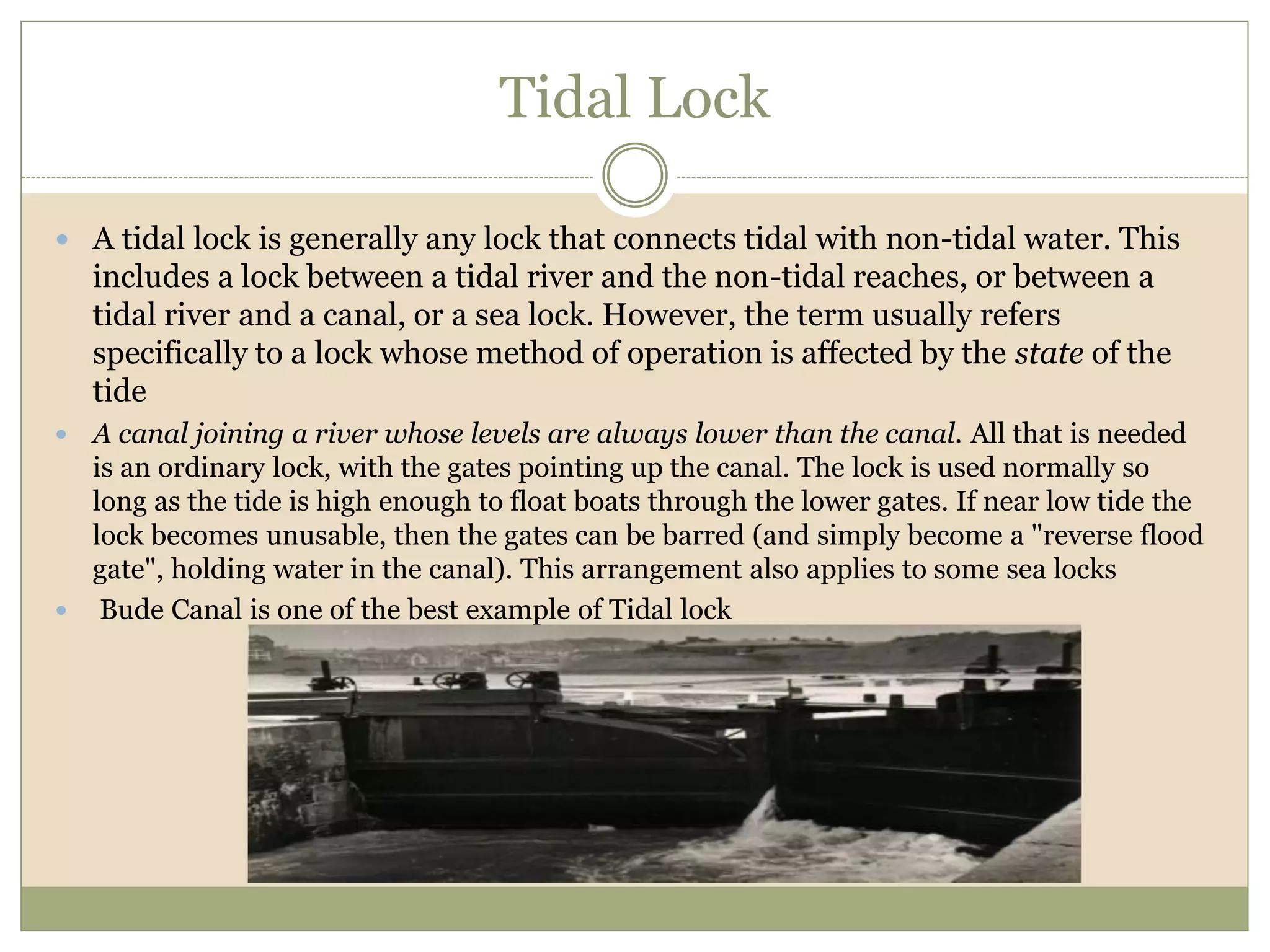
 Bude Canal is one of the best example of Tidal lock
HIRAM M. CHITTENDEN LOCKS
 Every November, the large lock of the Hiram M. Chittenden Locks (better known locally as
the "Ballard Locks" in reference to the Seattle neighborhood they are located in) was
emptied for maintenance, as seen in the November 2004 pictures below. This provides an
opportunity to visualize how a lock works without the water obscuring the bottom of the
lock
 The lock has three pairs of gates, one pair at each end and one pair in the middle so that
half the length of the lock can be used when the whole length is not required, thus saving
water.
 The barely visible person walking along the bottom of the lock in the second picture gives
an indication of the vast size of this lock.
 In both pictures of the end gates, the string of penstock openings are visible along the sides
at the bottom.
 The water entering and leaving the lock flows by gravity through these openings. It
requires around 15 minutes to fill or empty the lock.
Inclined Plane
 An inclined plane is a system used on some canals for raising boats between different
water levels. Boats may be conveyed afloat, in caissons, or may be carried in cradles or
slings. It can be considered as a specialised type of cable railway.
 An inclined plane is quicker, and wastes less water, than a flight of canal locks, but is
more costly to install and operate. A development of the idea is the water slope. Another
alternative to consecutive locks is a boat lift
 With caissons
 The Chesapeake and Ohio Canal in Washington, D.C. later had an inclined plane built to
move boats into the Potomac River so that they could bypass Georgetown which was
becoming congested with traffic.
 Foxton Inclined Plane
 Without caissons
 Bude Canal in Cornwall
 Morris Canal, Northern New Jersey
 St. Columb Canal built by John Edyvean
Marine Railway Lock
 A marine railway is similar to a canal inclined plane in that it moves boats up or
down a slope on rails. However, the vessel is carried "dry" (in a carrying frame, or
cradle) rather than in a water-filled caisson. The principle is based on the patent slip
used for hauling vessels out of the water for maintenance.
 In operation, a boat is navigated into the carrying frame, which has been lowered
into the water. The boat is secured to the cradle, possibly by raising slings under the
hull using hydraulics, and the cradle is hauled out of the water and up the hill with a
cable. At the top of the slope, the cradle is lowered into the upper waterway, and the
boat released. As the boat is not floating, Archimedes' principle does not apply, so
the weight lifted or lowered by the device varies - making counterbalancing (by dead
weights or a second boat carriage) more difficult.
 In some locations, notably the Big Chute Marine Railway on the Trent-Severn
Waterway, in Ontario, Canada, a marine railway was installed as a temporary
measure at the planned site of a flight of conventional locks. In this and several
other cases, the locks were never built, and the marine railway continued to serve on
a permanent basis.

BOAT LIFT
 A boat lift, ship lift, or lift lock is a machine for transporting boats between
water at two different elevations, and is an alternative to the CANAL LOCK and
the CANAL INCLINED PLANE.
 It may be either vertically moving, like the ship lifts in Germany, Belgium, the lift
at "Les Fontinettes" in France or the Anderton boat lift in England, or rotational,
like the Falkirk Wheel in Scotland.
CAISSON LOCKS
 A caisson lock was invented in the late 18th century as a
solution to minimise the use of great volumes of water
required to raise and lower canal boats through large height
differences.
 It was normal to only raise and lower boats through small
height differences of a few feet when traversing undulating
terrain. A solution was required when either large height
differences were encountered or water was in short supply.
 The boat entered the box and was sealed in by the door
closing behind it, and the box itself was moved up or down
through the water. When the box was at the bottom of the
chamber, it was under almost 60 feet (18 m) of water – at a
pressure of three atmospheres, in total. One of these "locks"
was built and demonstrated to the Prince
Regent (later George IV), but it had various engineering
problems and the design was not put into use on the Coal
Canal.
Use Of Lock In River Navigation
 When a stretch of river is made navigable, a lock is sometimes required to bypass an
obstruction such as a rapid dam, or mill weir — because of the change in river level across
the obstacle.
 In large scale river navigation improvements, weirs and locks are used together. A weir
will increase the depth of a shallow stretch, and the required lock will either be built in a
gap in the weir, or at the downstream end of an artificial cut which bypasses the weir and
perhaps a shallow stretch of river below it. A river improved by these means is often
called a Waterway or River Navigation
 example Calder and Hebble Navigation
 Where a longer cut bypasses a circuitous stretch of river, the upstream end of the cut will
often be protected by a flood lock.
 The longer the cut, the greater the difference in river level between start and end of the
cut, so that a very long cut will need additional locks along its length. At this point, the
cut is, in effect, a canal
CONCLUSION
 Lift locking permits easy transportation and navigation across long
stretches of water bodies which otherwise was expensive and time
consuming.
 Through high development of this mechanism, enhancement of
international as well as national trade and communication would be
possible.
 These systems could be deployed in a wide range of site conditions where
a short stretch consists of larger difference in the water level. Along with
aid in transportation, it facilitates the surrounding region of becoming a
tourist spot thus boosting its economy.
 With appropriate construction of reservoirs whose level are intermediate
between upper and lower pounds, it is possible to conserve the water that
goes unutilised during each cycle of lift locking.
 It is an excellent method of water control and management. This in turn
would help reduce the probability of the canal running dry
 All in all the cost of water transport has come down substantially, thanks
to the lift locking mechanism.
REFERENCE
1. https://en.wikipedia.org/wiki/Lock_(water_navig
ation)
2. "Foxton Inclined Plane Trust: Restoration".
Fipt.org.uk.
3. "Clydebank Drop Lock".
4. "Final Report of the International Commission for
the Study of Locks". Google Books.
5. "Lock". UXL Encyclopedia of Science
Navigating Locks: An Introduction to Lock Types and Operation

More Related Content

What's hot

Ce154 lecture 3 reservoirs, spillways, & energy dissipators
Ce154   lecture 3 reservoirs, spillways, & energy dissipatorsCe154   lecture 3 reservoirs, spillways, & energy dissipators
Ce154 lecture 3 reservoirs, spillways, & energy dissipatorsSudhir Jagtap
 
Spillways and Diversion Headwork's
Spillways and Diversion Headwork'sSpillways and Diversion Headwork's
Spillways and Diversion Headwork'skartikchourasia
 
design of chute and syphonspillway
design of chute and syphonspillwaydesign of chute and syphonspillway
design of chute and syphonspillwaychencho dema
 
Unit 3 spillway
Unit 3 spillwayUnit 3 spillway
Unit 3 spillwayMood Naik
 
Spillway and Fish Ladder
Spillway and Fish LadderSpillway and Fish Ladder
Spillway and Fish LadderAmir Adnan
 
Spillways2000 101110063804-phpapp02 - copy
Spillways2000 101110063804-phpapp02 - copySpillways2000 101110063804-phpapp02 - copy
Spillways2000 101110063804-phpapp02 - copybakht zamin
 
Canal outlets and modules
Canal outlets and modulesCanal outlets and modules
Canal outlets and modulesbhalinder singh
 
Spillway and its types
Spillway and its typesSpillway and its types
Spillway and its typesBilal Mirani
 
Spillways & energy dissipator
Spillways & energy dissipatorSpillways & energy dissipator
Spillways & energy dissipatorSAGAR RAUT
 
Seminar on spillway by Mr. Yash Upadhyay
Seminar on spillway by  Mr. Yash UpadhyaySeminar on spillway by  Mr. Yash Upadhyay
Seminar on spillway by Mr. Yash Upadhyayupadhyayyash
 
design of hydraulic controls and structures
design of hydraulic  controls and structuresdesign of hydraulic  controls and structures
design of hydraulic controls and structuresavirup naskar
 
050218 chapter 7 spillways and energy dissipators
050218 chapter 7 spillways and energy dissipators050218 chapter 7 spillways and energy dissipators
050218 chapter 7 spillways and energy dissipatorsBinu Karki
 
Canal outlets
Canal outletsCanal outlets
Canal outletssaibabu48
 
TYPES OF SPILLWAYS & PROMINENT FEATURES
TYPES OF SPILLWAYS & PROMINENT FEATURESTYPES OF SPILLWAYS & PROMINENT FEATURES
TYPES OF SPILLWAYS & PROMINENT FEATURESMalay Talaviya
 

What's hot (20)

Ce154 lecture 3 reservoirs, spillways, & energy dissipators
Ce154   lecture 3 reservoirs, spillways, & energy dissipatorsCe154   lecture 3 reservoirs, spillways, & energy dissipators
Ce154 lecture 3 reservoirs, spillways, & energy dissipators
 
Spillways
SpillwaysSpillways
Spillways
 
Spillways and Diversion Headwork's
Spillways and Diversion Headwork'sSpillways and Diversion Headwork's
Spillways and Diversion Headwork's
 
Regulation Works
Regulation WorksRegulation Works
Regulation Works
 
design of chute and syphonspillway
design of chute and syphonspillwaydesign of chute and syphonspillway
design of chute and syphonspillway
 
Spillways
SpillwaysSpillways
Spillways
 
Unit 3 spillway
Unit 3 spillwayUnit 3 spillway
Unit 3 spillway
 
Lecture 1 free overfall and ogee
Lecture 1 free overfall and ogeeLecture 1 free overfall and ogee
Lecture 1 free overfall and ogee
 
Spillway and Fish Ladder
Spillway and Fish LadderSpillway and Fish Ladder
Spillway and Fish Ladder
 
Spillways2000 101110063804-phpapp02 - copy
Spillways2000 101110063804-phpapp02 - copySpillways2000 101110063804-phpapp02 - copy
Spillways2000 101110063804-phpapp02 - copy
 
Canal outlets and modules
Canal outlets and modulesCanal outlets and modules
Canal outlets and modules
 
Spillway and its types
Spillway and its typesSpillway and its types
Spillway and its types
 
Spillways & energy dissipator
Spillways & energy dissipatorSpillways & energy dissipator
Spillways & energy dissipator
 
Seminar on spillway by Mr. Yash Upadhyay
Seminar on spillway by  Mr. Yash UpadhyaySeminar on spillway by  Mr. Yash Upadhyay
Seminar on spillway by Mr. Yash Upadhyay
 
design of hydraulic controls and structures
design of hydraulic  controls and structuresdesign of hydraulic  controls and structures
design of hydraulic controls and structures
 
050218 chapter 7 spillways and energy dissipators
050218 chapter 7 spillways and energy dissipators050218 chapter 7 spillways and energy dissipators
050218 chapter 7 spillways and energy dissipators
 
Canal outlets
Canal outletsCanal outlets
Canal outlets
 
Sluice gates
Sluice gatesSluice gates
Sluice gates
 
Spillways
SpillwaysSpillways
Spillways
 
TYPES OF SPILLWAYS & PROMINENT FEATURES
TYPES OF SPILLWAYS & PROMINENT FEATURESTYPES OF SPILLWAYS & PROMINENT FEATURES
TYPES OF SPILLWAYS & PROMINENT FEATURES
 

Similar to Navigating Locks: An Introduction to Lock Types and Operation

Similar to Navigating Locks: An Introduction to Lock Types and Operation (20)

Lock
LockLock
Lock
 
Polc Lock Curriculum
Polc Lock CurriculumPolc Lock Curriculum
Polc Lock Curriculum
 
4. Spillways.ppt
4. Spillways.ppt4. Spillways.ppt
4. Spillways.ppt
 
DIVERSION HEAD WORKS
DIVERSION HEAD WORKSDIVERSION HEAD WORKS
DIVERSION HEAD WORKS
 
Docks and their classification
Docks and their classificationDocks and their classification
Docks and their classification
 
Diversion head work
Diversion head workDiversion head work
Diversion head work
 
unit-3.pdf
unit-3.pdfunit-3.pdf
unit-3.pdf
 
SPILLWAYS.pdf
SPILLWAYS.pdfSPILLWAYS.pdf
SPILLWAYS.pdf
 
Canal structures
Canal structuresCanal structures
Canal structures
 
Canal structures
Canal structuresCanal structures
Canal structures
 
Barrage Gate Operation Rules and Silt Control Devices Report
Barrage Gate Operation Rules and Silt Control Devices Report Barrage Gate Operation Rules and Silt Control Devices Report
Barrage Gate Operation Rules and Silt Control Devices Report
 
H & d ppt 05 wet docks
H & d ppt 05 wet docksH & d ppt 05 wet docks
H & d ppt 05 wet docks
 
Spillways
SpillwaysSpillways
Spillways
 
Canal MASONRY WORK
Canal MASONRY WORKCanal MASONRY WORK
Canal MASONRY WORK
 
Hydraulic Structure Deep Hazam.pdf
Hydraulic Structure Deep Hazam.pdfHydraulic Structure Deep Hazam.pdf
Hydraulic Structure Deep Hazam.pdf
 
Berthing structures
Berthing structuresBerthing structures
Berthing structures
 
Presenation on Diversion Headworks irrigation.pptx
Presenation on Diversion Headworks irrigation.pptxPresenation on Diversion Headworks irrigation.pptx
Presenation on Diversion Headworks irrigation.pptx
 
Lecture 8
Lecture 8Lecture 8
Lecture 8
 
Ce 413 hydraulic structures 8th
Ce 413 hydraulic structures 8thCe 413 hydraulic structures 8th
Ce 413 hydraulic structures 8th
 
Spillway
SpillwaySpillway
Spillway
 

Navigating Locks: An Introduction to Lock Types and Operation

  • 2. 1. INTRODUCTION 2. Basic construction and operation 3. TYPES OF LOCK LIFT 1. STAIR CASE LOCK LIFT 2. DROP LOCK 3. FLOOD LOOK AND FLOOD GATES 4. TYPES OF FLOOD GATES 5. TIDAL LOCK 6. HIRAM M. 4. INCLINED PLANE 5. MARINE RAILWAY LOCK 6. BOAT LIFT 7. CAISSON LOCKS 8. Use Of Lock In River Navigation 9. CONCLUSION 10. REFERENCE CONTEXT
  • 3. INTRODUCTION  A lock is a device used for raising and lowering Boats, ships and other watercraft between stretches of water of different levels on river and canal waterways. The distinguishing feature of a lock is a fixed chamber in which the water level can be varied ,  where as in a caisson lock, a boat lift, or on a Canal inclined plane it is the chamber itself (usually then called a caisson ) that rises and falls.  Locks are used to make a river more easily navigable, or to allow a canal to take a reasonably direct line across land that is not level.
  • 4. Basic construction and operation • Construction •A watertight chamber connecting the upper and lower canals, and large enough to enclose one or more boats. The position of the chamber is fixed, but its water level can vary. • A gate (often a pair of "pointing" half-gates) at each end of the chamber. A gate is opened to allow a boat to enter or leave the chamber; when closed, the gate is watertight. • A set of lock gear to empty or fill the chamber as required. This is usually a simple valve which allows water to drain into or out of the chamber larger locks may use pumps. •Operation • The principle of operating a lock is simple. For instance, if a boat travelling downstream finds the lock already full of water: • The entrance gates are opened and the boat moves in. • The entrance gates are closed. • A valve is opened, this lowers the boat by draining water from the chamber. The exit gates are opened and the boat moves out
  • 5. • If the lock were empty, the boat would have had to wait 5 to 10 minutes while the lock was filled. For a boat travelling upstream, the process is reversed the boat enters the empty lock, and then the chamber is filled by opening a valve that allows water to enter the chamber from the upper level. • The whole operation will usually take between 10 and 20 minutes, depending on the size of the lock and whether the water in the lock was originally set at the boat's level. • Boaters approaching a lock are usually pleased to meet another boat coming towards them, because this boat will have just exited the lock on their level and therefore set the lock in their favour — saving about 5 to 10 minutes. However, this is not true for staircase lock, where it is quicker for boats to go through in convoy.
  • 6. Operation of a canal lock 1-3. Boat enters 'empty' lock 4. Bottom gates are closed, bottom paddles closed, top paddles opened, lock starts to fill 5. Lock is filling with water, lifting boat to the higher level
  • 7. TYPES OF LOCK LIFT 1.Staircase locks:- Staircase REAL APPARENT • A "real" staircase can be thought of as a "compressed" flight, where the intermediate pounds have disappeared, and the upper gate of one lock is also the lower gate of the one above it. • The absence of intermediate pounds, operating a staircase is very different from operating a flight. • As there is no intermediate pound, a chamber can only be filled by emptying the one above, or emptied by filling the one below thus the whole staircase has to be full of water (except for the bottom chamber) before a boat starts to ascend, or empty (except for the top chamber) before a boat starts to descend. • By building a pair of such lock sets (one used to climb and the other to descend) these difficulties are avoided, as well as enabling a greater traffic volume and reduced wait times. Examples of famous "real" staircases in England are BINGLEY and GRINDLEY BROOK
  • 8. APPARENT STAIR CASE  In an "apparent" staircase the chambers still have common gates, but the water does not pass directly from one chamber to the next, going instead via side ponds. This means it is not necessary to ensure that the flight is full or empty before starting.  Examples of "apparent" staircases are Foxton Lock and Watford Lock on the Leicester Branch of the Grand Union.
  • 9. Doubled Paired or Twinned Locks  Locks can be built side by side on the same waterway. This is variously called doubling, pairing, or twinning. The Panama Canal in U.S has three sets of double locks.  Doubling gives advantages in speed, avoiding hold-ups at busy times and increasing the chance of a boat finding a lock set in its favour.  There can also be water savings,the locks may be of different sizes, so that a small boat does not need to empty a large lock or each lock may be able to act as a side pond (water-saving basin) for the other.,  the word used is usually "twinned" here indicating the possibility of saving water by synchronising the operation of the chambers so that some water from the emptying chamber helps to fill the other.  Some famous Twinned locks Hillmorton on the Oxford Canal Elsewhere they are still in use; a pair of twinned locks has been opened in 2014 on the Dortmund-Ems Canal near Münster Germany
  • 10. DROP LOCKS  A drop lock allows a short length of canal to be lowered temporarily while a boat passes under an obstruction such as a low bridge. During canal restoration, a drop lock may be used where it is impractical or prohibitively expensive to remove or raise a structure that was built after the canal was closed  A drop lock can consist of two conventional lock chambers leading to a sump pound, or a single long chamber incorporating the sump - although the term properly applies only to the second case.  As the pounds at either end of the structure are at the same height, the lock can only be emptied either by allowing water to run to waste from the sump to a lower stream or drain, or by pumping water back up to the canal.  Particularly in the two-chamber type, there would be a need for a bypass culvert, to allow water to move along the interrupted pound and so supply locks further down the canal.  In the case of the single-chamber type, this can be achieved by keeping the lock full and leaving the gates open while not in use  the only example in the world of a drop lock that has actually been constructed is at Dalmuir on the Forth and Clyde Canal in Scotland
  • 11. Flood Locks and Flood Gates  Flood Lock:-  A flood lock is to prevent a river from flooding a connected waterway. It is typically installed where a canal leaves a river. At normal river levels, the lock gates are left open, and the height of the canal is allowed to rise and fall with the height of the river.  However, if the river floods beyond a safe limit for the canal, then the gates are closed (and an extra lock created) until the river drops again. Since this is a true lock it is possible for boats to leave the canal for the flooded river despite the difference in water levels (though this is not likely to be wise) or (more sensibly) to allow boats caught out on the flood to gain refuge in the canal.  Note that if the canal is simply a navigation cut connecting two stretches of the same river, the flood lock will be at the upstream end of the cut (the downstream end will have a conventional lock).  A good example is on the Calder and Hebble Navigation, where structures referred to in the boating guides as "Flood Locks" are clearly only capable of being used for flood-prevention, not for "penning" boats to or from the river in flood.  Flood Gates:-  Floodgates, also called stop gates, are adjustable gates used to control water flow in flood barriers , reservoir, river, stream or levee systems. They may be designed to set spillway crest heights in dams, to adjust flow rates in canals, or they may be designed to stop water flow entirely as part of a levee or storm surge system.  Since most of these devices operate by controlling the water surface elevation being stored or routed, they are also known as crest gates. In the case of flood bypass systems, floodgates sometimes are also used to lower the water levels in a main river or canal channels by allowing more water to flow into a flood bypass or detention basin when the main river or canal is approaching a flood stage. 
  • 12. Types Of Flood gates  Bulkhead gates:- are vertical walls with movable, or re-movable, sections. Movable sections can be lifted to allow water to pass underneath (as in a sluice gate) and over the top of the structure.  Hinged crest gates:- are wall sections that rotate from vertical to horizontal, thereby varying the height of the dam. They are generally controlled with hydraulic power, although some are passive and are powered by the water being impounded.  Radial gates:- are rotary gates consisting of cylindrical sections. They may rotate vertically or horizontally. Tainter gates are a vertical design that rotates up to allow water to pass underneath. Low friction trunnion bearings, along with a face shape that balances hydrostatic forces, allow this design to close under its own weight as a safety feature
  • 13. Types Of Flood gates  Drum gates:- are hollow gate sections that float on water. They are pinned to rotate up or down. Water is allowed into or out of the flotation chamber to adjust the dam's crest height  Roller gates:- are large cylinders that move in an angled slot. They are hoisted with a chain and have a cogged design that interfaces with their slot  Clamshell gates:- have an external clamshell leaf design.
  • 14. Tidal Lock  A tidal lock is generally any lock that connects tidal with non-tidal water. This includes a lock between a tidal river and the non-tidal reaches, or between a tidal river and a canal, or a sea lock. However, the term usually refers specifically to a lock whose method of operation is affected by the state of the tide  A canal joining a river whose levels are always lower than the canal. All that is needed is an ordinary lock, with the gates pointing up the canal. The lock is used normally so long as the tide is high enough to float boats through the lower gates. If near low tide the lock becomes unusable, then the gates can be barred (and simply become a "reverse flood gate", holding water in the canal). This arrangement also applies to some sea locks  Bude Canal is one of the best example of Tidal lock
  • 15. HIRAM M. CHITTENDEN LOCKS  Every November, the large lock of the Hiram M. Chittenden Locks (better known locally as the "Ballard Locks" in reference to the Seattle neighborhood they are located in) was emptied for maintenance, as seen in the November 2004 pictures below. This provides an opportunity to visualize how a lock works without the water obscuring the bottom of the lock  The lock has three pairs of gates, one pair at each end and one pair in the middle so that half the length of the lock can be used when the whole length is not required, thus saving water.  The barely visible person walking along the bottom of the lock in the second picture gives an indication of the vast size of this lock.  In both pictures of the end gates, the string of penstock openings are visible along the sides at the bottom.  The water entering and leaving the lock flows by gravity through these openings. It requires around 15 minutes to fill or empty the lock.
  • 16. Inclined Plane  An inclined plane is a system used on some canals for raising boats between different water levels. Boats may be conveyed afloat, in caissons, or may be carried in cradles or slings. It can be considered as a specialised type of cable railway.  An inclined plane is quicker, and wastes less water, than a flight of canal locks, but is more costly to install and operate. A development of the idea is the water slope. Another alternative to consecutive locks is a boat lift  With caissons  The Chesapeake and Ohio Canal in Washington, D.C. later had an inclined plane built to move boats into the Potomac River so that they could bypass Georgetown which was becoming congested with traffic.  Foxton Inclined Plane  Without caissons  Bude Canal in Cornwall  Morris Canal, Northern New Jersey  St. Columb Canal built by John Edyvean
  • 17. Marine Railway Lock  A marine railway is similar to a canal inclined plane in that it moves boats up or down a slope on rails. However, the vessel is carried "dry" (in a carrying frame, or cradle) rather than in a water-filled caisson. The principle is based on the patent slip used for hauling vessels out of the water for maintenance.  In operation, a boat is navigated into the carrying frame, which has been lowered into the water. The boat is secured to the cradle, possibly by raising slings under the hull using hydraulics, and the cradle is hauled out of the water and up the hill with a cable. At the top of the slope, the cradle is lowered into the upper waterway, and the boat released. As the boat is not floating, Archimedes' principle does not apply, so the weight lifted or lowered by the device varies - making counterbalancing (by dead weights or a second boat carriage) more difficult.  In some locations, notably the Big Chute Marine Railway on the Trent-Severn Waterway, in Ontario, Canada, a marine railway was installed as a temporary measure at the planned site of a flight of conventional locks. In this and several other cases, the locks were never built, and the marine railway continued to serve on a permanent basis. 
  • 18. BOAT LIFT  A boat lift, ship lift, or lift lock is a machine for transporting boats between water at two different elevations, and is an alternative to the CANAL LOCK and the CANAL INCLINED PLANE.  It may be either vertically moving, like the ship lifts in Germany, Belgium, the lift at "Les Fontinettes" in France or the Anderton boat lift in England, or rotational, like the Falkirk Wheel in Scotland.
  • 19. CAISSON LOCKS  A caisson lock was invented in the late 18th century as a solution to minimise the use of great volumes of water required to raise and lower canal boats through large height differences.  It was normal to only raise and lower boats through small height differences of a few feet when traversing undulating terrain. A solution was required when either large height differences were encountered or water was in short supply.  The boat entered the box and was sealed in by the door closing behind it, and the box itself was moved up or down through the water. When the box was at the bottom of the chamber, it was under almost 60 feet (18 m) of water – at a pressure of three atmospheres, in total. One of these "locks" was built and demonstrated to the Prince Regent (later George IV), but it had various engineering problems and the design was not put into use on the Coal Canal.
  • 20. Use Of Lock In River Navigation  When a stretch of river is made navigable, a lock is sometimes required to bypass an obstruction such as a rapid dam, or mill weir — because of the change in river level across the obstacle.  In large scale river navigation improvements, weirs and locks are used together. A weir will increase the depth of a shallow stretch, and the required lock will either be built in a gap in the weir, or at the downstream end of an artificial cut which bypasses the weir and perhaps a shallow stretch of river below it. A river improved by these means is often called a Waterway or River Navigation  example Calder and Hebble Navigation  Where a longer cut bypasses a circuitous stretch of river, the upstream end of the cut will often be protected by a flood lock.  The longer the cut, the greater the difference in river level between start and end of the cut, so that a very long cut will need additional locks along its length. At this point, the cut is, in effect, a canal
  • 21. CONCLUSION  Lift locking permits easy transportation and navigation across long stretches of water bodies which otherwise was expensive and time consuming.  Through high development of this mechanism, enhancement of international as well as national trade and communication would be possible.  These systems could be deployed in a wide range of site conditions where a short stretch consists of larger difference in the water level. Along with aid in transportation, it facilitates the surrounding region of becoming a tourist spot thus boosting its economy.  With appropriate construction of reservoirs whose level are intermediate between upper and lower pounds, it is possible to conserve the water that goes unutilised during each cycle of lift locking.  It is an excellent method of water control and management. This in turn would help reduce the probability of the canal running dry  All in all the cost of water transport has come down substantially, thanks to the lift locking mechanism.
  • 22. REFERENCE 1. https://en.wikipedia.org/wiki/Lock_(water_navig ation) 2. "Foxton Inclined Plane Trust: Restoration". Fipt.org.uk. 3. "Clydebank Drop Lock". 4. "Final Report of the International Commission for the Study of Locks". Google Books. 5. "Lock". UXL Encyclopedia of Science

Editor's Notes

  1. "real" and "apparent"