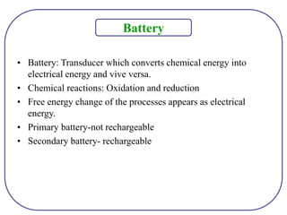
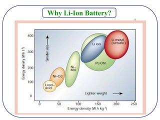
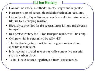
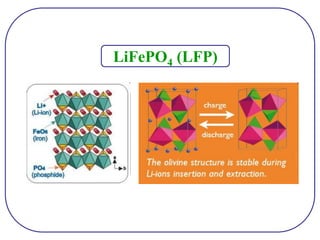
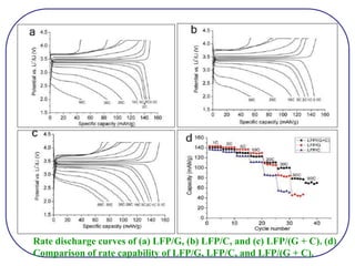
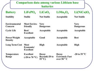
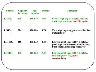
Li Ion Battery (LIB)
K.Devaki
• Battery: Transducer which converts chemical energy into
electrical energy and vive versa.
• Chemical reactions: Oxidation and reduction
• Free energy change of the processes appears as electrical
energy.
• Primary battery-not rechargeable
• Secondary battery- rechargeable
Battery
Why Li-Ion Battery?
Lead acid battery
Appealing to industrial
applications due to
• Reliable
• Inexpensive
Disadvantages
• Low life cycle
• Low energy density
(30 ~ 40 Wh/Kg)
Ni metal hydride battery
Appealing to hybrid electric
vehicle applications due to
• Rechargeable
• No memory effect
• High power density
• High energy density
• Currently available battery
capacity : 1.5 kWh
Disadvantages
• Self discharge rates
Recharge-ability : Basically, when the direction of electron
discharge (negative to positive) is reversed, restoring power.
Memory Effect : When a battery is repeatedly recharged
before it has discharged more than half of its power, it will
“forget” its original power capacity.
Cadmium crystals have the memory effect (NiCd)
J. Mater. Chem., 19 (2009) 5871
Schematic of Li Ion Battery
The cathode half reaction (with charging being forwards) is:
LiCoO2 ↔ Li 1-x CoO2 + xLi+ + xe-
The anode half reaction is:
xLi + + xe- + 6C ↔ Lix C6
• Contains an anode, a cathode, an electrolyte and separator.
• Harnesses a set of reversible oxidation/reduction reactions.
• Li ion dissolved by a discharge reaction and returns to metallic
lithium by a charging reaction
• Electrolyte provides for the separation of Li ions and electron
transport.
• In a perfect battery the Li ion transport number will be unity.
• Cell potential is determined by ∆G= -EF
• The electrode system must be both a good ionic and an
electronic conductor.
• It is necessary to add an electronically conductive material
such as carbon black.
• To hold the electrode together, a binder is also needed.
Li Ion Battery
Advantages
• Li has greatest
electrochemical potential
• Lighter than others
• Shape and size variation
• High open circuit voltage
• No memory effect
• Low discharge rate 5-10%.
Disadvantages
• Internal resistance of lithium
ion battery is high as
compared to other batteries.
• Due to overcharging and
high temperature capacity will
diminish.
Existing Li-Ion Electrodes
Graphite – 370 mA.h/g LiCoO2– 140 mA.h/g
The development of materials for LIB centres around
“intercalation” and suitable electrolyte with appropriate
“potential window”.
• Intercalation is an equilibrium process and governed by the free
energy considerations.
• Entropy factor may predominate over the enthalpy factor.
• The lattice in which intercalation takes place should be capable of
interacting electronically without affecting the translational
entropy of the intercalant.
• The value of the equilibrium constant of the intercalation and
deintercalation reaction should be near 1.
Intercalation
• Should be completely reversible.
• Should be geometrically and electronically fitting to the inter
planar spacing.
• Should be capable of electron exchange.
• Other substrates like mesoporous carbon and other pillared
materials can also be considered.
Intercalation
• The selection of the electrolyte depends on the potential window.
• Potentials are beyond water potential and hence non aqueous
electrolyte.
• It should not reactive with Li+ ions, since it will decide the
transport of the Li+ ions for the intercalation reaction.
• The electrolyte solution commonly comprises a lithium salt
dissolved in a mixture of organic solvents.
• Examples include LiPF6 or LiBOB (the BOB is the anion with
the boron coordinated by two oxalate groups) in an ethylene
carbonate/dimethyl carbonate solvent.
Electrolyte
Graphite is commonly selected anode material in LIB due to its
• High coulombic efficiency.
• However, the specific capacity of graphite is relatively low
(theoretical value: 372mA.h/g) since every six carbon atoms can
host only one lithium ion by forming an intercalation compound
(LiC6).
• Sn: 993 mA.h/g, Si: 4200 mA.h/g) than graphite via the
formation of alloys with lithium or through the reversible
reactions with lithium ions.
• Drawback of these substances as anode materials is the huge
volume variation during the charge/discharge process which
causes the pulverization of the electrode, resulting in poor
reversibility.
Graphite
• Reducing the size of these materials to nanometer scale can
partially suppress the expansion and shrinkage of the anode
materials.
• By designing the structure of these materials as hollow
spherical or porous particles can improve the lithium storage
capacity and their initial Coulombic efficiency as well to a certain
degree.
• However, the capacity decay of the electrode along with the
charge/discharge cycling still can not be completely avoided.
Basic building block for all
forms of graphitic material
made up of monolayer C atoms
tightly packed into 2D
honeycomb lattice.
Remarkable properties
Young’s modulus - 1,100GPa
Fracture strength - 125GPa
Mobility of charge carriers - 200,000
cm2 V-1 s-1
Thermal conductivity - 5,000 W m-1K-1
Specific surface area - 2630 m2g-1
0D 1D 3D
2D
K. S. Novoselov, Nature, 438 (2005) 197.
Graphene
• Graphene, a two-dimensional aromatic monolayer of carbon
atom, is actually the building unit of graphite.
• Recently, metal oxides nanoparticles encapsulated by graphene
layers have been reported to display high specific capacity and
excellent cycling performance as anode materials.
• The structure, in which the graphene layers acted as both a
‘‘buffer zone’’ of volume variation of the nanoparticles and a
good electron transfer medium.
Graphene
Schematic illustrations of graphene based carbonaceous materials
with ordered graphene structures (A-C) and disordered graphene
structures (D-E), and intercalation of Li ions in the ordered (G)
and disordered (H) graphenes.
Key Issues
• Low theoretical capacity (372 mA.h/g) (Due to perfection of
graphene structure and dense packing of the graphene layers).
• Long diffusion distance of lithium ions into its host position
between the graphene layers (Due to large graphene size).
• One of the simple ways to shorten the diffusion distance of
lithium ion is to minimize the size of graphenes in the graphitic
materials.
• However, a more efficient way is to arrange the graphene
layers into a nanoscale one-dimensional fiber with graphene
layers oriented perpendicular to the fiber axis (CNFs).
• Reversible capacity : 461 mA.h/g @ 0.1 C
170 mA.h/g @ 10 C
• Coulombic efficiency : 95 %
• The smaller the diameter of the CNF, the better the rate
capability.
J. Mater. Chem., 2009, 19, 5871
• The exfoliated graphite oxide nanoplatelets showed a very high
reversible specific capacity of more than 1000 mA.h/g when they
were incorporated with polyelectrolytes into a layer-by-layer
structure.
• The exfoliation and chemical modification of graphene were
believed to be the main reasons for the performance
enhancement.
• The modification of graphite actually led to disordered carbon,
for which the electrochemical mechanism was believed to be
different from that of graphitic carbon.
• The single layer graphene in disordered carbon was proposed to
form Li2C6 since both of the graphene surfaces could host lithium
ions.
• The reversible capacity increased with the increase of single
layer graphene fraction as well as the micro-porosity in the
disordered carbon.
• Porosity is important for improving the capacity and cycling
performance of disordered carbon anode materials.
• However porosity can somehow reduce the energy density of
the anode materials.
Disordered Graphene materials
Key Requirements for Cathode
• The discharge reaction should have large negative Gibbs free
energy (high discharge voltage).
• The host structure must have low molecular weight and the
ability to intercalate large amounts of lithium (high energy
capacity).
• The host structure must have high lithium chemical diffusion
coefficient (high power density).
• The structural modifications during intercalation and
deintercalation should be as small as possible (long life cycle).
• The materials should be chemically stable, non-toxic and
inexpensive.
• The handling of the materials should be easy.
Typical energy densities of lead, nickel- and lithium-based batteries
• LiCoO2 is the most widely used positive electrode.
• The theoretical capacity of LiCoO2 is approximately
274mAhg−1.
• The practical capacity is limited to almost half the theoretical
value due to a hexagonal to monoclinic phase transformation upon
charging between 4.15 and 4.2V.
• The dissolution of cobalt ions (Co4+) has also been reported as a
reason for the deterioration of the crystal structure.
• In order to prevent phase instability, the substitution of
metal elements for Co in LiCoO2 or a surface coating has been
suggested.
• Various metal oxides (e.g.,MgO,Al2O3, ZnO) and metal
phosphates (e.g., AlPO4, FePO4) have been coated on the surface
of LiCoO2 and reported to improve the cyclability of LiCoO2.
LiCoO2
J. Power Sources 188 (2009) 583
V2O5 Coated LiCoO2
(a) First charge and discharge curves of samples with a cut-off voltage ranging
from 3.0 to 4.2 (b) Cycle-life performance of samples with cut-off voltage
ranging from 3.0 to 4.4 V.
J. Power Sources 132 (2004) 195
MgO Coated LiCoO2
(a) Plots of specific discharge capacities (b) Plots of Cycling stability
.
Chem. Mater. 2000, 12, 3788
Al2O3 Coated LiCoO2
(a) Initial capacities and (b) cycle-life performances of bare and coated LiCoO2
cathodes measured at the rate of 0.5C between 4.4 and 2.75 V in Li/LiCoO2.
Al2O3 Coated LiCoO2
(a) Cyclic
voltammograms of the
uncoated LiCoO2
cathode and
(b) Al2O3-coated
LiCoO2 cathode. The
scan rate was 0.02
mV/s.
H and M in (a) denote
the hexagonal and
monoclinic phase,
respectively.
Al2O3 Coated LiCoO2
Plots of capacity
retention of (a) bare
LiCoO2 and
(b) coated LiCoO2
heat-treated at 600 °C
for 3 h as a function of
cycle number. Charge
and discharge rates are
0.5- and 1C,
respectively.
• The coating of vanadium oxides imparts a better cycle
performance at a high-charge cut-off voltage by preventing cation
mixing during cycling and reducing the active surface area that
contacts the electrolyte.
• MgO  probably due to the electrochemical inactivity of MgO
particles.
• The improved cycle performance is due to the formation of
amorphous Al2O3 layer on the surface of LiCoO2 particles. The
Al2O3 film could prevent Co dissolution from the LiCoO2
structure and decrease the capacity loss.
LiFePO4 (LFP)
1. Thermal stability
• LiFePO4 is made of a skeleton of PO4 polyanions that is very
stable thermally while favorable to one dimensional Li+ ion
reversible diffusion.
• Covalent P-O bond stabilize the oxide when fully charged and
avoid O2 release making LiFePO4 the most stable commercial
cathode material.
• Has stability and tolerance to overcharge.
2. Good electrochemical characteristics
• Long calendar life for the stable olivine structure.
• High tolerance to high and low-voltage abuse.
• Lower thickness change of full cell during charge and discharge.
3. Abundant resource of basic elements
4. Environmentally friendly
LiFePO4 Characteristics
Why C-LiFePO4 ?
LFP has attracted much attention due to
• Low cost
• Low toxicity
• Relatively large capacity
But, Electrochemical performance deteriorate with increasing
charge/discharge rates due to its low electronic conductivity and
Li ion diffusion rate.
Followed Strategies to improve the performance
• Carbon coating
• Metal loading
• Particle size reduction
• Core shell LFP/C nanocomposite – 90 mA h/ g at 60C.
• Highly dispersed LFP nanoparticles on nanoporous carbon
discharge at a rate of up to 230C.
• Lithium phosphate coated LFP nanoparticles could be
discharged in 10-20s.
Illustration of the preparation process and the microscale structure of
LFP/graphene composite.
J. Mater. Chem., 2011, 21, 3353
• (a,b) SEM images showing
an overview of the LFP/G
particles.
• (c) TEM image
• (d) corresponding elemental
map using EELS.
where red represents the
LFP
nanoparticles and the green
represents graphene sheets.
• (e) TEM image on the edge
of individual microspheres.
• (f) TEM image showing a 3D
graphene network
• (a,b) SEM images of LFP/C and
LFP/(G + C) secondary particles.
• (c,d) SEM images with a high
magnification showing the surface
of an individual LFP/C and
LFP/(G + C) secondary particles.
• (e,f) TEM image illustrating a
local area of one LFP nanoparticle
in an LFP/C and LFP/(G+C)
secondary particles.
Raman spectra of LFP/C,
LFP/(G + C), and LFP/G.
XPS spectra of LFP/G,
LFP/(G + C), and LFP/C.
Rate discharge curves of (a) LFP/G, (b) LFP/C, and (c) LFP/(G + C). (d)
Comparison of rate capability of LFP/G, LFP/C, and LFP/(G + C).
Comparison data among various Lithium base
batteries
Battery LiFePO4 LiCoO2 LiMn2O4 Li(NiCo)O2
Stability Stable Not Stable Acceptable Not Stable
Environmental
Concern
Most Enviro-
friendly
Very
Dangerous
Very
Dangerous
Cycle Life Best/
Excellent
Acceptable Acceptable Acceptable
Power/Weight
Density
Acceptable Good Acceptable Best
Long Term Cost Most
Economic/
Excellent
High Acceptable High
Temperature
Range
Excellent
(-20 to 70 °C)
Decay
Beyond(-20 to
55 °C)
Decay
Extremely Fast
over 50 ° C
-20 to 55 °C
Material Capacity
in theory
Real
capacity
Density Character
LiCoO2 275 130-140 5.00 Stable, high capacity ratio, smooth
discharge platform, low life cycle
LiNiO2 274 170-180 4.78 Very high capacity, poor stability, low
material cost
LiMnO4 148 100-120 4.28 Low material cost, better in safety,
poor high temperature performance,
Poor charge/discharge character
LiFePO4 170 120-160 3.25 Low material cost, better in safety,
very long cycle life, poor
conductivity
Baterias LIB.ppt

Baterias LIB.ppt

  • 1.
    Li Ion Battery(LIB) K.Devaki
  • 2.
    • Battery: Transducerwhich converts chemical energy into electrical energy and vive versa. • Chemical reactions: Oxidation and reduction • Free energy change of the processes appears as electrical energy. • Primary battery-not rechargeable • Secondary battery- rechargeable Battery
  • 3.
  • 4.
    Lead acid battery Appealingto industrial applications due to • Reliable • Inexpensive Disadvantages • Low life cycle • Low energy density (30 ~ 40 Wh/Kg) Ni metal hydride battery Appealing to hybrid electric vehicle applications due to • Rechargeable • No memory effect • High power density • High energy density • Currently available battery capacity : 1.5 kWh Disadvantages • Self discharge rates
  • 5.
    Recharge-ability : Basically,when the direction of electron discharge (negative to positive) is reversed, restoring power. Memory Effect : When a battery is repeatedly recharged before it has discharged more than half of its power, it will “forget” its original power capacity. Cadmium crystals have the memory effect (NiCd)
  • 6.
    J. Mater. Chem.,19 (2009) 5871 Schematic of Li Ion Battery The cathode half reaction (with charging being forwards) is: LiCoO2 ↔ Li 1-x CoO2 + xLi+ + xe- The anode half reaction is: xLi + + xe- + 6C ↔ Lix C6
  • 7.
    • Contains ananode, a cathode, an electrolyte and separator. • Harnesses a set of reversible oxidation/reduction reactions. • Li ion dissolved by a discharge reaction and returns to metallic lithium by a charging reaction • Electrolyte provides for the separation of Li ions and electron transport. • In a perfect battery the Li ion transport number will be unity. • Cell potential is determined by ∆G= -EF • The electrode system must be both a good ionic and an electronic conductor. • It is necessary to add an electronically conductive material such as carbon black. • To hold the electrode together, a binder is also needed. Li Ion Battery
  • 8.
    Advantages • Li hasgreatest electrochemical potential • Lighter than others • Shape and size variation • High open circuit voltage • No memory effect • Low discharge rate 5-10%. Disadvantages • Internal resistance of lithium ion battery is high as compared to other batteries. • Due to overcharging and high temperature capacity will diminish.
  • 9.
    Existing Li-Ion Electrodes Graphite– 370 mA.h/g LiCoO2– 140 mA.h/g
  • 11.
    The development ofmaterials for LIB centres around “intercalation” and suitable electrolyte with appropriate “potential window”. • Intercalation is an equilibrium process and governed by the free energy considerations. • Entropy factor may predominate over the enthalpy factor. • The lattice in which intercalation takes place should be capable of interacting electronically without affecting the translational entropy of the intercalant. • The value of the equilibrium constant of the intercalation and deintercalation reaction should be near 1. Intercalation
  • 12.
    • Should becompletely reversible. • Should be geometrically and electronically fitting to the inter planar spacing. • Should be capable of electron exchange. • Other substrates like mesoporous carbon and other pillared materials can also be considered. Intercalation
  • 13.
    • The selectionof the electrolyte depends on the potential window. • Potentials are beyond water potential and hence non aqueous electrolyte. • It should not reactive with Li+ ions, since it will decide the transport of the Li+ ions for the intercalation reaction. • The electrolyte solution commonly comprises a lithium salt dissolved in a mixture of organic solvents. • Examples include LiPF6 or LiBOB (the BOB is the anion with the boron coordinated by two oxalate groups) in an ethylene carbonate/dimethyl carbonate solvent. Electrolyte
  • 14.
    Graphite is commonlyselected anode material in LIB due to its • High coulombic efficiency. • However, the specific capacity of graphite is relatively low (theoretical value: 372mA.h/g) since every six carbon atoms can host only one lithium ion by forming an intercalation compound (LiC6). • Sn: 993 mA.h/g, Si: 4200 mA.h/g) than graphite via the formation of alloys with lithium or through the reversible reactions with lithium ions. • Drawback of these substances as anode materials is the huge volume variation during the charge/discharge process which causes the pulverization of the electrode, resulting in poor reversibility. Graphite
  • 15.
    • Reducing thesize of these materials to nanometer scale can partially suppress the expansion and shrinkage of the anode materials. • By designing the structure of these materials as hollow spherical or porous particles can improve the lithium storage capacity and their initial Coulombic efficiency as well to a certain degree. • However, the capacity decay of the electrode along with the charge/discharge cycling still can not be completely avoided.
  • 16.
    Basic building blockfor all forms of graphitic material made up of monolayer C atoms tightly packed into 2D honeycomb lattice. Remarkable properties Young’s modulus - 1,100GPa Fracture strength - 125GPa Mobility of charge carriers - 200,000 cm2 V-1 s-1 Thermal conductivity - 5,000 W m-1K-1 Specific surface area - 2630 m2g-1 0D 1D 3D 2D K. S. Novoselov, Nature, 438 (2005) 197. Graphene
  • 17.
    • Graphene, atwo-dimensional aromatic monolayer of carbon atom, is actually the building unit of graphite. • Recently, metal oxides nanoparticles encapsulated by graphene layers have been reported to display high specific capacity and excellent cycling performance as anode materials. • The structure, in which the graphene layers acted as both a ‘‘buffer zone’’ of volume variation of the nanoparticles and a good electron transfer medium. Graphene
  • 18.
    Schematic illustrations ofgraphene based carbonaceous materials with ordered graphene structures (A-C) and disordered graphene structures (D-E), and intercalation of Li ions in the ordered (G) and disordered (H) graphenes.
  • 19.
    Key Issues • Lowtheoretical capacity (372 mA.h/g) (Due to perfection of graphene structure and dense packing of the graphene layers). • Long diffusion distance of lithium ions into its host position between the graphene layers (Due to large graphene size). • One of the simple ways to shorten the diffusion distance of lithium ion is to minimize the size of graphenes in the graphitic materials. • However, a more efficient way is to arrange the graphene layers into a nanoscale one-dimensional fiber with graphene layers oriented perpendicular to the fiber axis (CNFs).
  • 20.
    • Reversible capacity: 461 mA.h/g @ 0.1 C 170 mA.h/g @ 10 C • Coulombic efficiency : 95 % • The smaller the diameter of the CNF, the better the rate capability. J. Mater. Chem., 2009, 19, 5871
  • 21.
    • The exfoliatedgraphite oxide nanoplatelets showed a very high reversible specific capacity of more than 1000 mA.h/g when they were incorporated with polyelectrolytes into a layer-by-layer structure. • The exfoliation and chemical modification of graphene were believed to be the main reasons for the performance enhancement. • The modification of graphite actually led to disordered carbon, for which the electrochemical mechanism was believed to be different from that of graphitic carbon.
  • 22.
    • The singlelayer graphene in disordered carbon was proposed to form Li2C6 since both of the graphene surfaces could host lithium ions. • The reversible capacity increased with the increase of single layer graphene fraction as well as the micro-porosity in the disordered carbon. • Porosity is important for improving the capacity and cycling performance of disordered carbon anode materials. • However porosity can somehow reduce the energy density of the anode materials. Disordered Graphene materials
  • 23.
    Key Requirements forCathode • The discharge reaction should have large negative Gibbs free energy (high discharge voltage). • The host structure must have low molecular weight and the ability to intercalate large amounts of lithium (high energy capacity). • The host structure must have high lithium chemical diffusion coefficient (high power density). • The structural modifications during intercalation and deintercalation should be as small as possible (long life cycle). • The materials should be chemically stable, non-toxic and inexpensive. • The handling of the materials should be easy.
  • 24.
    Typical energy densitiesof lead, nickel- and lithium-based batteries
  • 25.
    • LiCoO2 isthe most widely used positive electrode. • The theoretical capacity of LiCoO2 is approximately 274mAhg−1. • The practical capacity is limited to almost half the theoretical value due to a hexagonal to monoclinic phase transformation upon charging between 4.15 and 4.2V. • The dissolution of cobalt ions (Co4+) has also been reported as a reason for the deterioration of the crystal structure. • In order to prevent phase instability, the substitution of metal elements for Co in LiCoO2 or a surface coating has been suggested. • Various metal oxides (e.g.,MgO,Al2O3, ZnO) and metal phosphates (e.g., AlPO4, FePO4) have been coated on the surface of LiCoO2 and reported to improve the cyclability of LiCoO2. LiCoO2
  • 26.
    J. Power Sources188 (2009) 583 V2O5 Coated LiCoO2 (a) First charge and discharge curves of samples with a cut-off voltage ranging from 3.0 to 4.2 (b) Cycle-life performance of samples with cut-off voltage ranging from 3.0 to 4.4 V.
  • 27.
    J. Power Sources132 (2004) 195 MgO Coated LiCoO2 (a) Plots of specific discharge capacities (b) Plots of Cycling stability
  • 28.
    . Chem. Mater. 2000,12, 3788 Al2O3 Coated LiCoO2 (a) Initial capacities and (b) cycle-life performances of bare and coated LiCoO2 cathodes measured at the rate of 0.5C between 4.4 and 2.75 V in Li/LiCoO2.
  • 29.
    Al2O3 Coated LiCoO2 (a)Cyclic voltammograms of the uncoated LiCoO2 cathode and (b) Al2O3-coated LiCoO2 cathode. The scan rate was 0.02 mV/s. H and M in (a) denote the hexagonal and monoclinic phase, respectively.
  • 30.
    Al2O3 Coated LiCoO2 Plotsof capacity retention of (a) bare LiCoO2 and (b) coated LiCoO2 heat-treated at 600 °C for 3 h as a function of cycle number. Charge and discharge rates are 0.5- and 1C, respectively.
  • 31.
    • The coatingof vanadium oxides imparts a better cycle performance at a high-charge cut-off voltage by preventing cation mixing during cycling and reducing the active surface area that contacts the electrolyte. • MgO  probably due to the electrochemical inactivity of MgO particles. • The improved cycle performance is due to the formation of amorphous Al2O3 layer on the surface of LiCoO2 particles. The Al2O3 film could prevent Co dissolution from the LiCoO2 structure and decrease the capacity loss.
  • 32.
  • 33.
    1. Thermal stability •LiFePO4 is made of a skeleton of PO4 polyanions that is very stable thermally while favorable to one dimensional Li+ ion reversible diffusion. • Covalent P-O bond stabilize the oxide when fully charged and avoid O2 release making LiFePO4 the most stable commercial cathode material. • Has stability and tolerance to overcharge. 2. Good electrochemical characteristics • Long calendar life for the stable olivine structure. • High tolerance to high and low-voltage abuse. • Lower thickness change of full cell during charge and discharge. 3. Abundant resource of basic elements 4. Environmentally friendly LiFePO4 Characteristics
  • 34.
  • 35.
    LFP has attractedmuch attention due to • Low cost • Low toxicity • Relatively large capacity But, Electrochemical performance deteriorate with increasing charge/discharge rates due to its low electronic conductivity and Li ion diffusion rate. Followed Strategies to improve the performance • Carbon coating • Metal loading • Particle size reduction • Core shell LFP/C nanocomposite – 90 mA h/ g at 60C. • Highly dispersed LFP nanoparticles on nanoporous carbon discharge at a rate of up to 230C. • Lithium phosphate coated LFP nanoparticles could be discharged in 10-20s.
  • 36.
    Illustration of thepreparation process and the microscale structure of LFP/graphene composite. J. Mater. Chem., 2011, 21, 3353
  • 37.
    • (a,b) SEMimages showing an overview of the LFP/G particles. • (c) TEM image • (d) corresponding elemental map using EELS. where red represents the LFP nanoparticles and the green represents graphene sheets. • (e) TEM image on the edge of individual microspheres. • (f) TEM image showing a 3D graphene network
  • 38.
    • (a,b) SEMimages of LFP/C and LFP/(G + C) secondary particles. • (c,d) SEM images with a high magnification showing the surface of an individual LFP/C and LFP/(G + C) secondary particles. • (e,f) TEM image illustrating a local area of one LFP nanoparticle in an LFP/C and LFP/(G+C) secondary particles.
  • 39.
    Raman spectra ofLFP/C, LFP/(G + C), and LFP/G. XPS spectra of LFP/G, LFP/(G + C), and LFP/C.
  • 40.
    Rate discharge curvesof (a) LFP/G, (b) LFP/C, and (c) LFP/(G + C). (d) Comparison of rate capability of LFP/G, LFP/C, and LFP/(G + C).
  • 41.
    Comparison data amongvarious Lithium base batteries Battery LiFePO4 LiCoO2 LiMn2O4 Li(NiCo)O2 Stability Stable Not Stable Acceptable Not Stable Environmental Concern Most Enviro- friendly Very Dangerous Very Dangerous Cycle Life Best/ Excellent Acceptable Acceptable Acceptable Power/Weight Density Acceptable Good Acceptable Best Long Term Cost Most Economic/ Excellent High Acceptable High Temperature Range Excellent (-20 to 70 °C) Decay Beyond(-20 to 55 °C) Decay Extremely Fast over 50 ° C -20 to 55 °C
  • 42.
    Material Capacity in theory Real capacity DensityCharacter LiCoO2 275 130-140 5.00 Stable, high capacity ratio, smooth discharge platform, low life cycle LiNiO2 274 170-180 4.78 Very high capacity, poor stability, low material cost LiMnO4 148 100-120 4.28 Low material cost, better in safety, poor high temperature performance, Poor charge/discharge character LiFePO4 170 120-160 3.25 Low material cost, better in safety, very long cycle life, poor conductivity