BATCH-3-MINIPROJECT-PPT.ppt it is helpful for people
1.
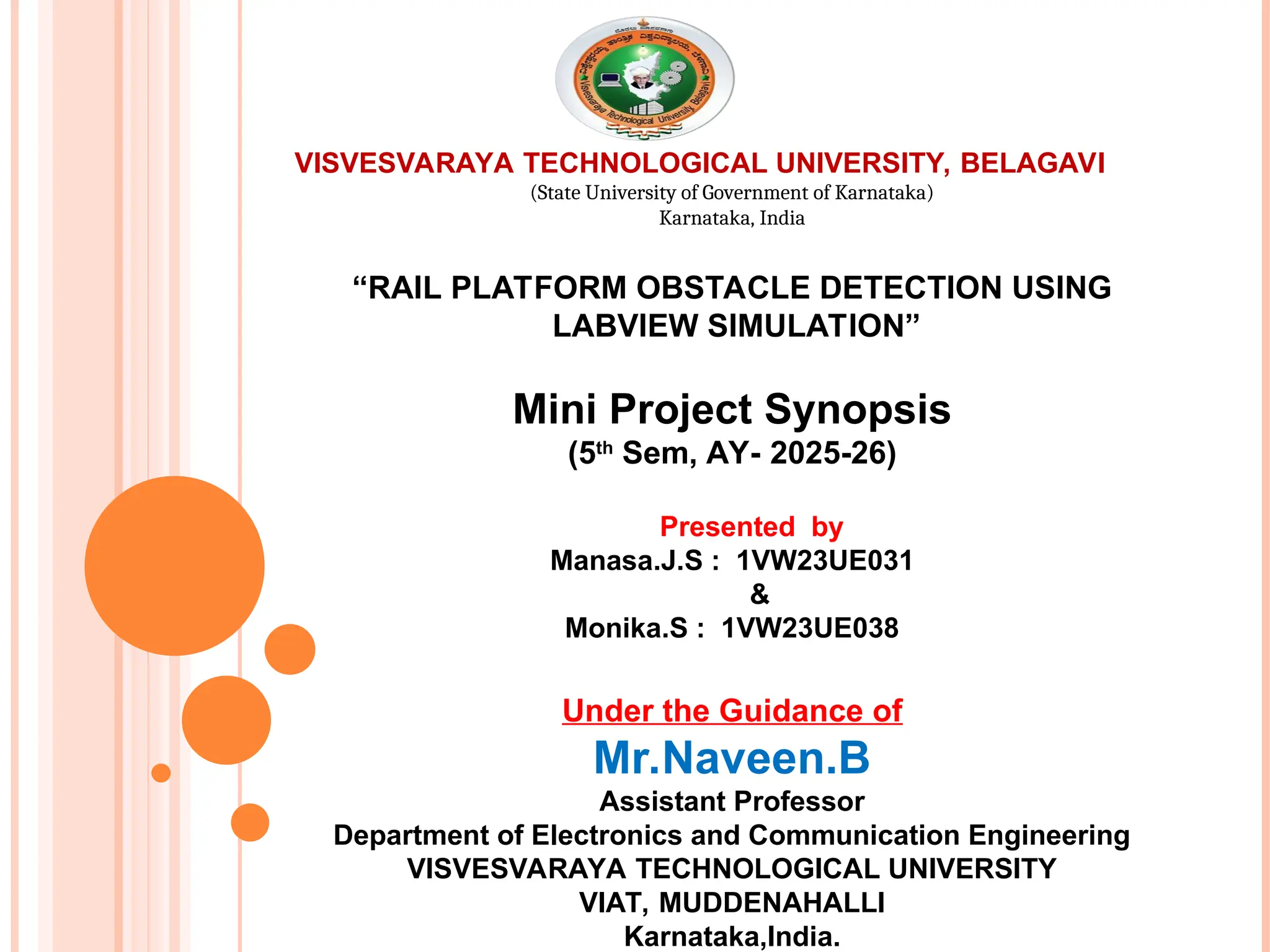
VISVESVARAYA TECHNOLOGICAL UNIVERSITY,BELAGAVI
(State University of Government of Karnataka)
Karnataka, India
“RAIL PLATFORM OBSTACLE DETECTION USING
LABVIEW SIMULATION”
Mini Project Synopsis
(5th
Sem, AY- 2025-26)
Presented by
Manasa.J.S : 1VW23UE031
&
Monika.S : 1VW23UE038
Under the Guidance of
Mr.Naveen.B
Assistant Professor
Department of Electronics and Communication Engineering
VISVESVARAYA TECHNOLOGICAL UNIVERSITY
VIAT, MUDDENAHALLI
Karnataka,India.
2.
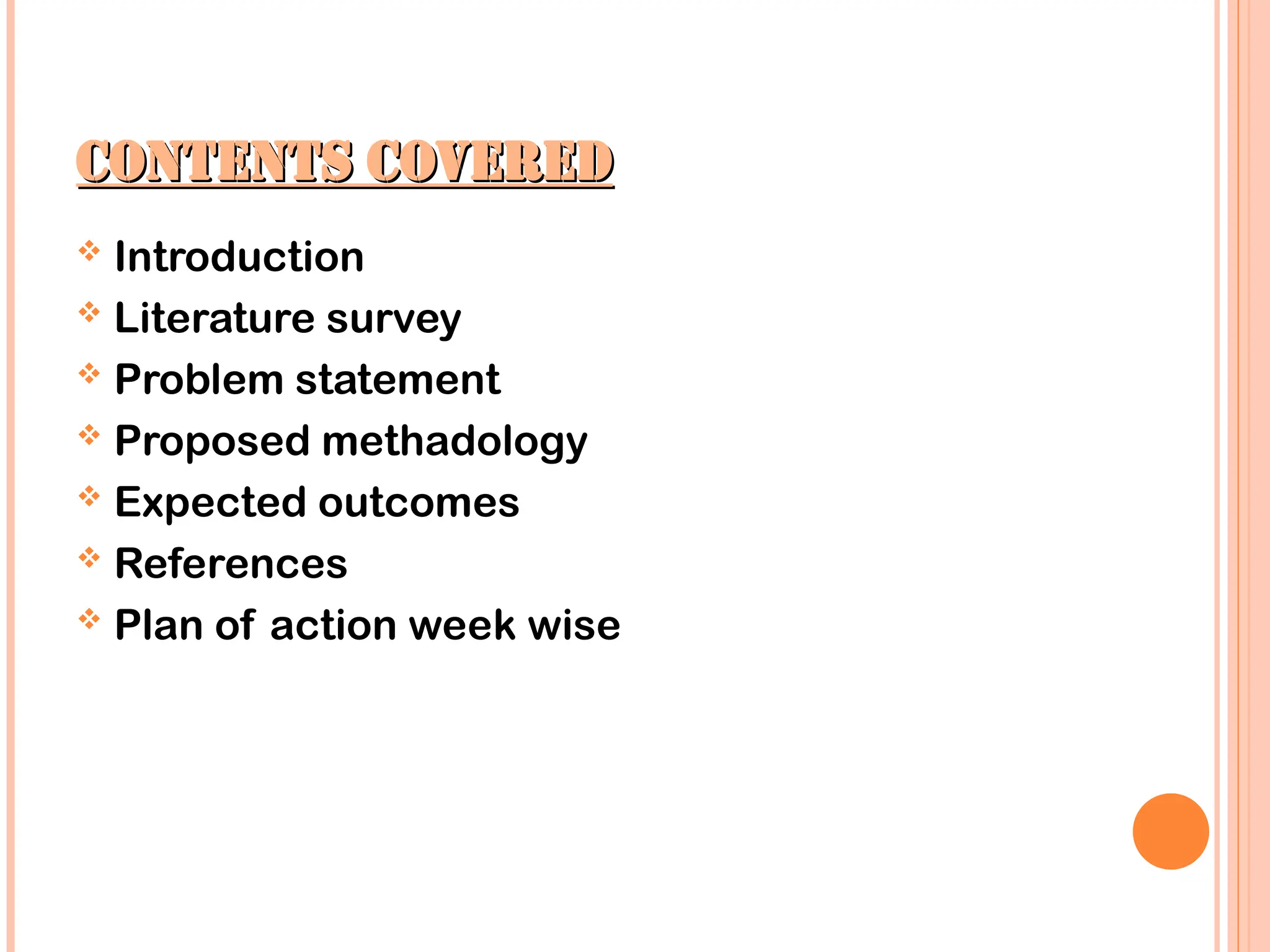
CONTENTS COVERED
CONTENTS COVERED
Introduction
Literature survey
Problem statement
Proposed methadology
Expected outcomes
References
Plan of action week wise
3.
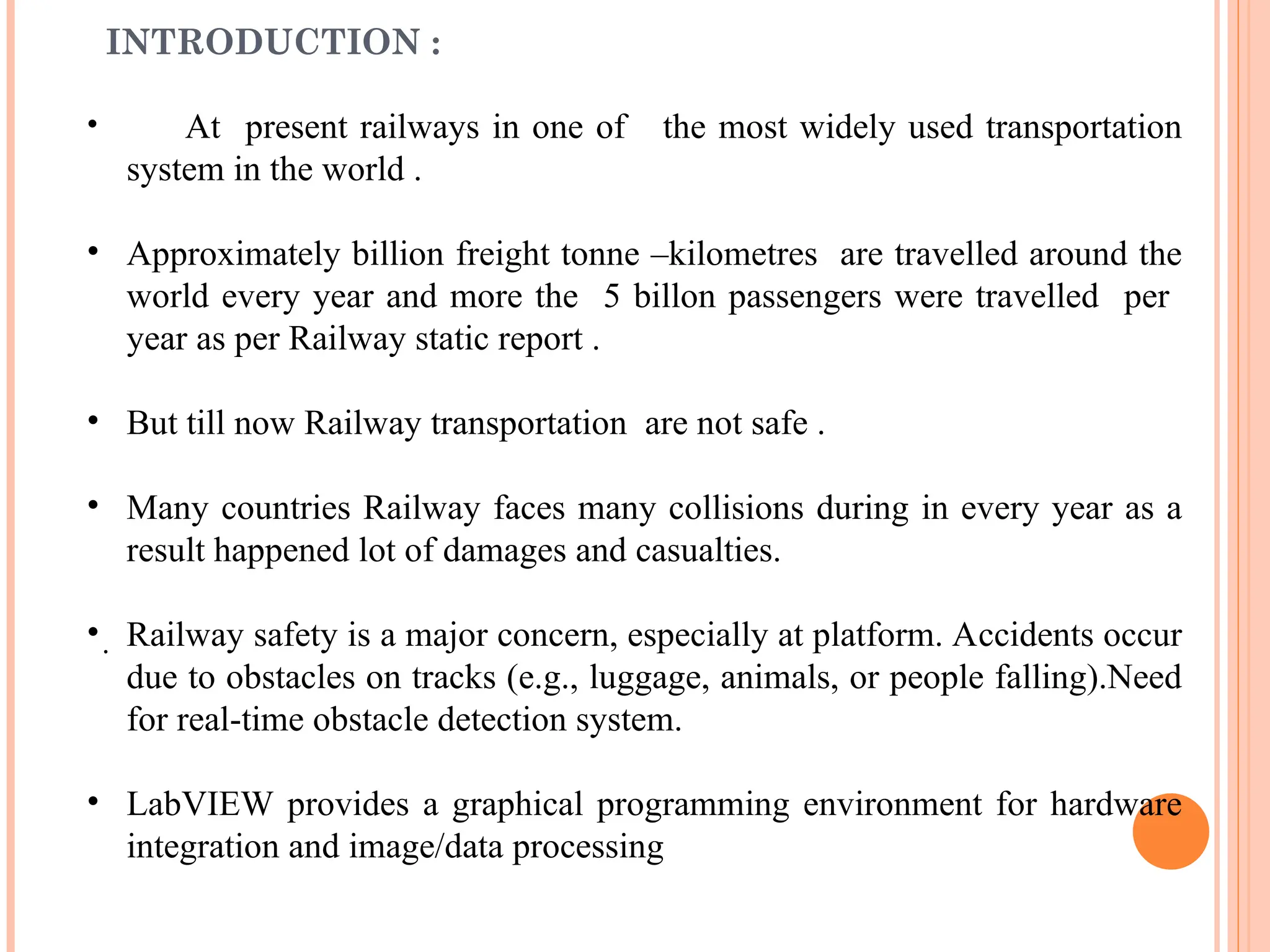
INTRODUCTION :
• Atpresent railways in one of the most widely used transportation
system in the world .
• Approximately billion freight tonne –kilometres are travelled around the
world every year and more the 5 billon passengers were travelled per
year as per Railway static report .
• But till now Railway transportation are not safe .
• Many countries Railway faces many collisions during in every year as a
result happened lot of damages and casualties.
• Railway safety is a major concern, especially at platform. Accidents occur
due to obstacles on tracks (e.g., luggage, animals, or people falling).Need
for real-time obstacle detection system.
• LabVIEW provides a graphical programming environment for hardware
integration and image/data processing
.
4.
LITERATURE SURVEY
Ref YearSensors Used Application Strengths Limitations
[1] Kim et al. 2008
Multiple 2D Laser
Scanners
UGV – drivable
environment detection
Reduces occlusion,
extends coverage,
reliable ground
estimation
Limited vertical
perception; requires
accurate alignment
[2] Maire 2007 Vision (mono/stereo)
Rail track
maintenance – anti-
collision
Low-cost, effective in
constrained rail
geometry
Sensitive to
lighting/weather;
possible false
detections
[3] Moon et al. 2007
Laser Scanner +
Vision
UGV – obstacle
detection
Sensor fusion
improves accuracy;
reduces false alarms
Needs precise
calibration &
synchronization
[4] Wender &
Dietmayer
2008
3D Laser Scanner +
Camera
Road vehicle detection
Accurate 3D
localization and
detection
High computational
cost; calibration
complexity
[5] Zhao et al. 2007
Multiple Lasers +
Cameras
Mobile platforms –
sensor calibration
Efficient extrinsic
calibration enables
reliable fusion
Requires re-
calibration; feature-
rich environments
needed
[6] Roberts & Corke 2000 2D Laser
Mining vehicles –
obstacle detection
Robust in dusty/harsh
environments
Cannot detect
overhangs; limited
FOV; dust
interference
[7] Oh et al. 2009 Stereo Vision
Railway platforms –
passenger safety
monitoring
Provides depth for
safety zone
monitoring; improves
passenger safety
Sensitive to
illumination; stereo
noise; real-time
challenges
5.
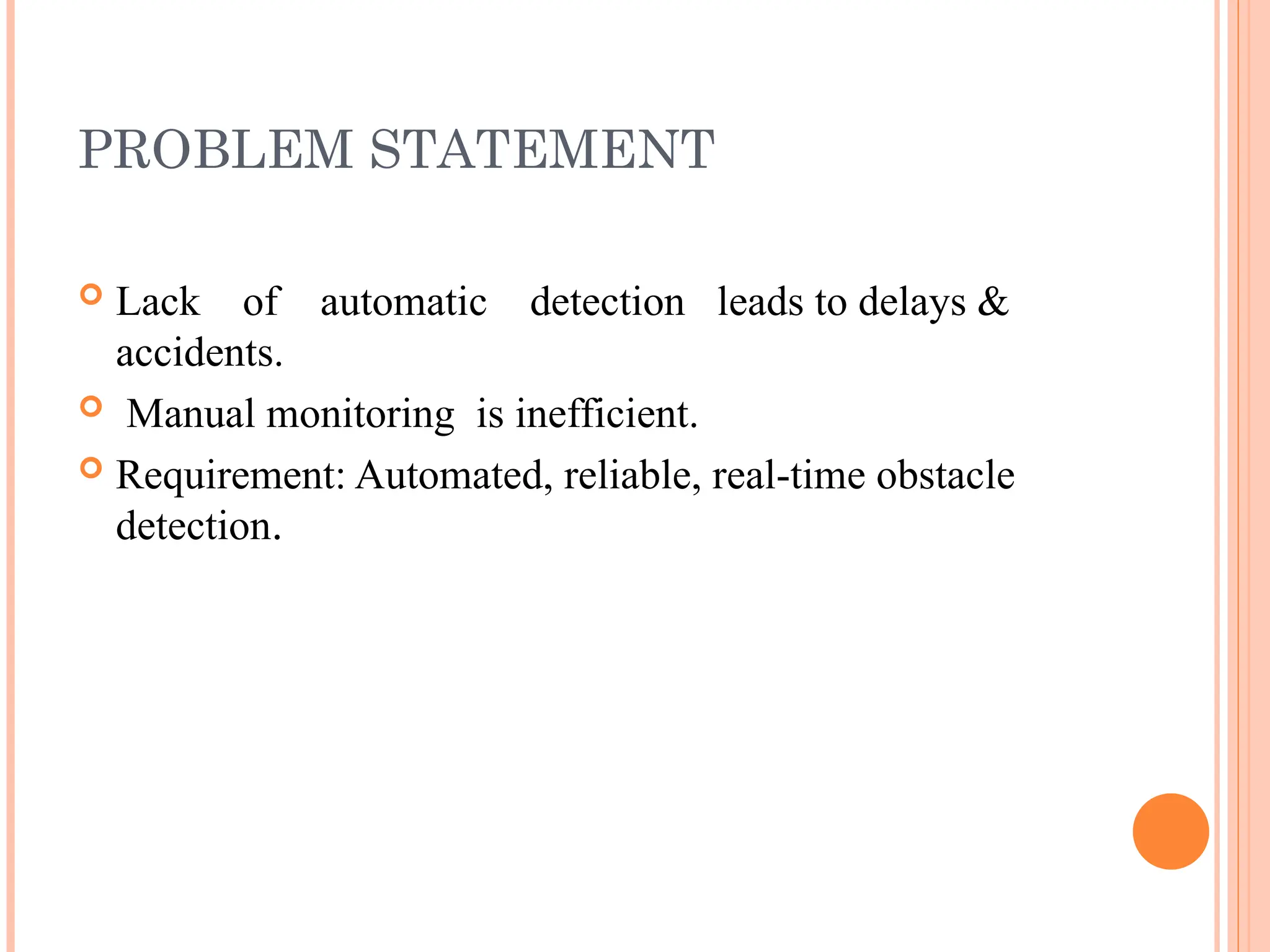
PROBLEM STATEMENT
Lackof automatic detection leads to delays &
accidents.
Manual monitoring is inefficient.
Requirement: Automated, reliable, real-time obstacle
detection.
6.
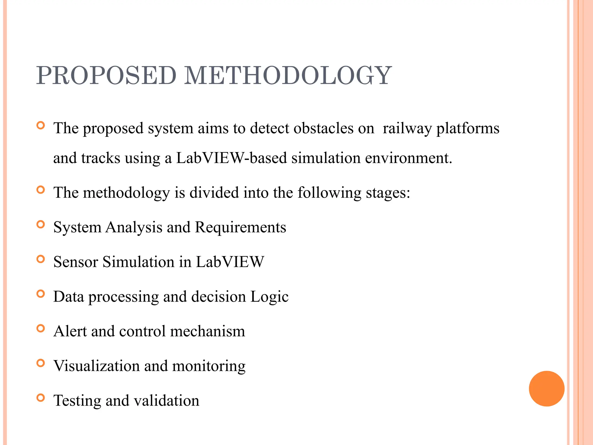
PROPOSED METHODOLOGY
Theproposed system aims to detect obstacles on railway platforms
and tracks using a LabVIEW-based simulation environment.
The methodology is divided into the following stages:
System Analysis and Requirements
Sensor Simulation in LabVIEW
Data processing and decision Logic
Alert and control mechanism
Visualization and monitoring
Testing and validation
7.
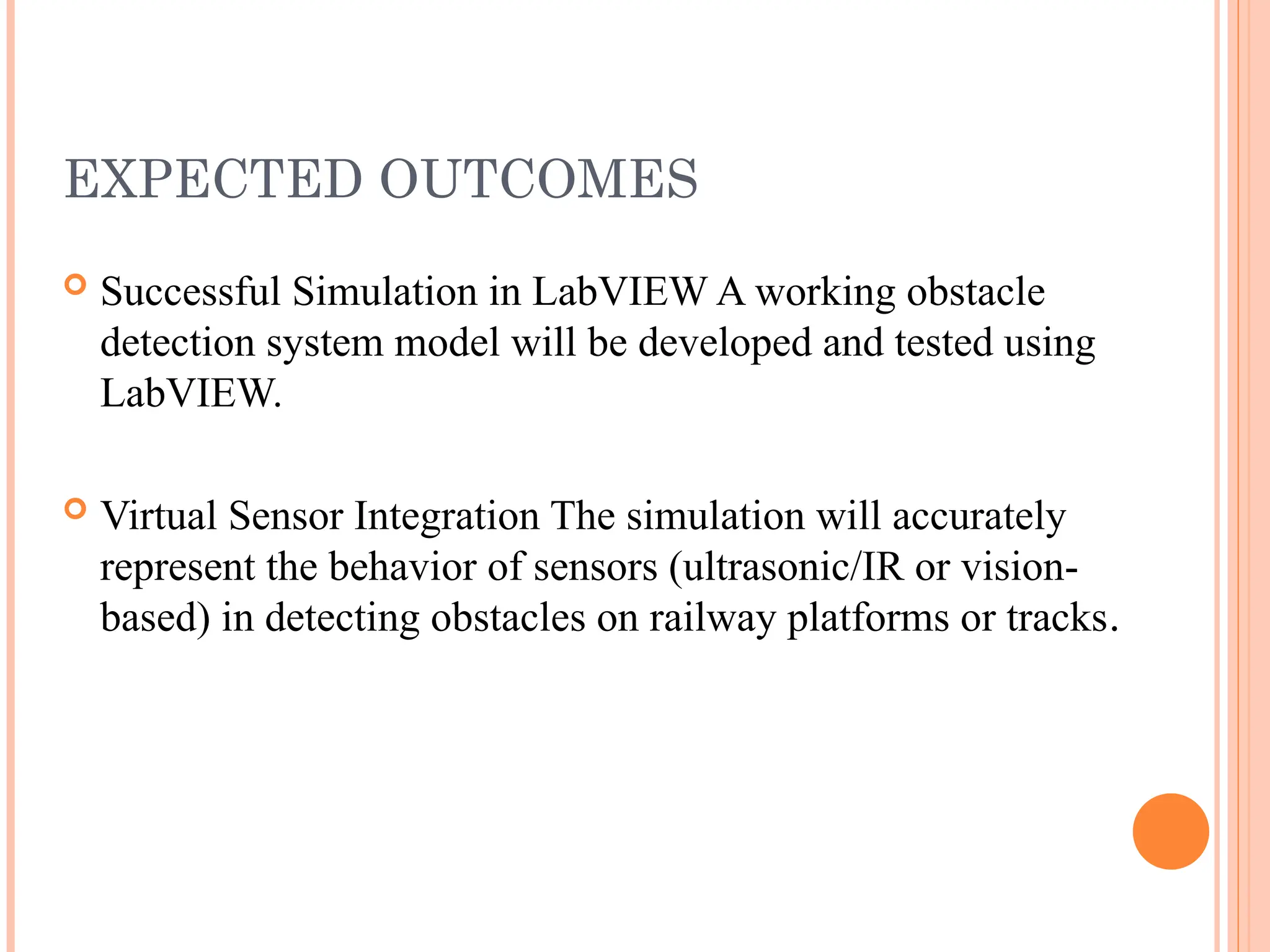
EXPECTED OUTCOMES
SuccessfulSimulation in LabVIEW A working obstacle
detection system model will be developed and tested using
LabVIEW.
Virtual Sensor Integration The simulation will accurately
represent the behavior of sensors (ultrasonic/IR or vision-
based) in detecting obstacles on railway platforms or tracks.
8.
REFERENCES
[1] J.H.Kim, S.H Lee and J.Ha. Kim, “Detection of a drivable environment
for UGV using multiple laser sensors,” International Conference on
Control, Automation and Systems, pp. 590-594, 2008.
[2] F. Maire, “Vision based anti-collision system for rail track maintenance
vehicles,” Advanced Video and Signal Based Surveillance, IEEE, pp. 170-
175, 2007.
[3] H.C. Moon, J.H. Kim and J.Ha. Kim, “Obstacle detecting system for
unmanned ground vehicle using laser scanner and vision,” International
Conference on Control, Automation and Systems, pp. 1758-1761, 2007.
9.
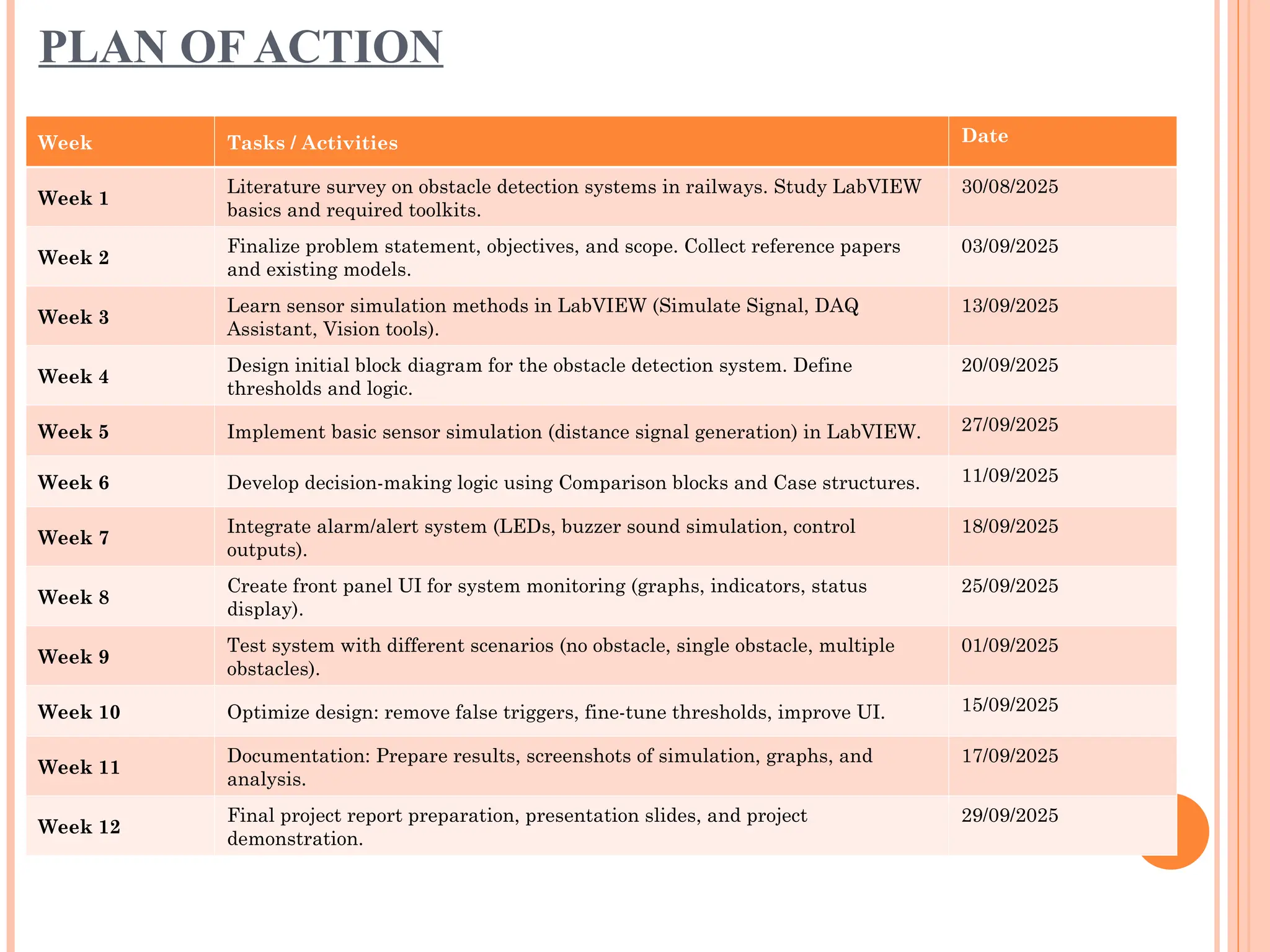
PLAN OF ACTION
WeekTasks / Activities Date
Week 1
Literature survey on obstacle detection systems in railways. Study LabVIEW
basics and required toolkits.
30/08/2025
Week 2
Finalize problem statement, objectives, and scope. Collect reference papers
and existing models.
03/09/2025
Week 3
Learn sensor simulation methods in LabVIEW (Simulate Signal, DAQ
Assistant, Vision tools).
13/09/2025
Week 4
Design initial block diagram for the obstacle detection system. Define
thresholds and logic.
20/09/2025
Week 5 Implement basic sensor simulation (distance signal generation) in LabVIEW. 27/09/2025
Week 6 Develop decision-making logic using Comparison blocks and Case structures. 11/09/2025
Week 7
Integrate alarm/alert system (LEDs, buzzer sound simulation, control
outputs).
18/09/2025
Week 8
Create front panel UI for system monitoring (graphs, indicators, status
display).
25/09/2025
Week 9
Test system with different scenarios (no obstacle, single obstacle, multiple
obstacles).
01/09/2025
Week 10 Optimize design: remove false triggers, fine-tune thresholds, improve UI. 15/09/2025
Week 11
Documentation: Prepare results, screenshots of simulation, graphs, and
analysis.
17/09/2025
Week 12
Final project report preparation, presentation slides, and project
demonstration.
29/09/2025
10.
/
Week Tasks /Activities
Week 1
Literature survey on
obstacle detection systems
in railways. Study
LabVIEW basics and
required toolkits.
Week 2
Finalize problem
statement, objectives, and
scope. Collect reference
papers and existing
models.
Week 3
Learn sensor simulation
methods in LabVIEW
(Simulate Signal, DAQ
Assistant, Vision tools).
Week 4
Design initial block
diagram for the obstacle
detection system. Define
thresholds and logic.
Week 5
Implement basic sensor
simulation (distance
signal generation) in
LabVIEW.
Week 6
Develop decision-making
logic using Comparison
blocks and Case
structures.
Week 7
Integrate alarm/alert
system (LEDs, buzzer
sound simulation, control
outputs).
Week 8
Create front panel UI for
system monitoring
(graphs, indicators, status
display).
Week 9
Test system with different
scenarios (no obstacle,
single obstacle, multiple
obstacles).
Week 10
Optimize design: remove
false triggers, fine-tune
thresholds, improve UI.
Week 11
Documentation: Prepare
results, screenshots of
simulation, graphs, and
analysis.
Week 12
Final project report
preparation, presentation
slides, and project
demonstration.
![LITERATURE SURVEY
Ref Year Sensors Used Application Strengths Limitations
[1] Kim et al. 2008
Multiple 2D Laser
Scanners
UGV – drivable
environment detection
Reduces occlusion,
extends coverage,
reliable ground
estimation
Limited vertical
perception; requires
accurate alignment
[2] Maire 2007 Vision (mono/stereo)
Rail track
maintenance – anti-
collision
Low-cost, effective in
constrained rail
geometry
Sensitive to
lighting/weather;
possible false
detections
[3] Moon et al. 2007
Laser Scanner +
Vision
UGV – obstacle
detection
Sensor fusion
improves accuracy;
reduces false alarms
Needs precise
calibration &
synchronization
[4] Wender &
Dietmayer
2008
3D Laser Scanner +
Camera
Road vehicle detection
Accurate 3D
localization and
detection
High computational
cost; calibration
complexity
[5] Zhao et al. 2007
Multiple Lasers +
Cameras
Mobile platforms –
sensor calibration
Efficient extrinsic
calibration enables
reliable fusion
Requires re-
calibration; feature-
rich environments
needed
[6] Roberts & Corke 2000 2D Laser
Mining vehicles –
obstacle detection
Robust in dusty/harsh
environments
Cannot detect
overhangs; limited
FOV; dust
interference
[7] Oh et al. 2009 Stereo Vision
Railway platforms –
passenger safety
monitoring
Provides depth for
safety zone
monitoring; improves
passenger safety
Sensitive to
illumination; stereo
noise; real-time
challenges](https://image.slidesharecdn.com/batch-3-miniproject-ppt-250822142531-ee6f1ffc/75/BATCH-3-MINIPROJECT-PPT-ppt-it-is-helpful-for-people-4-2048.jpg)
![REFERENCES
[1] J.H. Kim, S.H Lee and J.Ha. Kim, “Detection of a drivable environment
for UGV using multiple laser sensors,” International Conference on
Control, Automation and Systems, pp. 590-594, 2008.
[2] F. Maire, “Vision based anti-collision system for rail track maintenance
vehicles,” Advanced Video and Signal Based Surveillance, IEEE, pp. 170-
175, 2007.
[3] H.C. Moon, J.H. Kim and J.Ha. Kim, “Obstacle detecting system for
unmanned ground vehicle using laser scanner and vision,” International
Conference on Control, Automation and Systems, pp. 1758-1761, 2007.](https://image.slidesharecdn.com/batch-3-miniproject-ppt-250822142531-ee6f1ffc/75/BATCH-3-MINIPROJECT-PPT-ppt-it-is-helpful-for-people-8-2048.jpg)