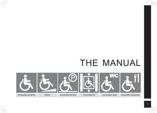
This document provides design guidelines for creating a barrier-free built environment. It covers topics such as signage, anthropometrics, accessible routes, entrances, doors, washrooms, drinking fountains, kitchens, storage, telephones, alarms, controls and more. The guidelines include specifications for dimensions, slopes, clearances and other accessibility features. The goal is to make buildings and public spaces usable by all people, including those with disabilities or temporary mobility impairments. Following these guidelines can help create an environment that is accessible and dignified for people of all abilities.


![85
A
L
A
R
M
S
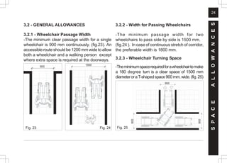
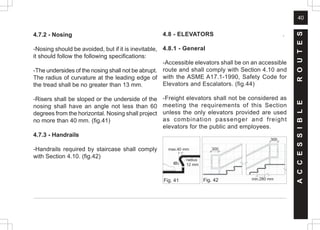
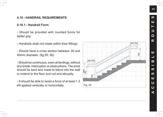
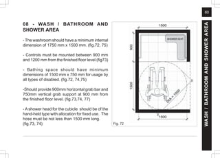
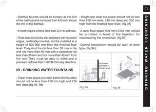
15 - ALARMS .
15.1 LOCATION
- At a minimum, visual signal appliances shall
be provided in buildings and facilities in each of
the following areas: rest-rooms and any other
general use areas (e.g. meeting rooms),
hallways, lobbies, and any other area for
common use.
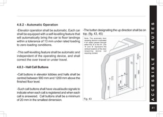
15.2 AUDIBLE ALARMS
- If provided, audible emergency alarms shall
produce a sound that exceeds the prevailing
equivalent sound level in the room or space by
at least 15 dbA or exceeds any maximum sound
level with a duration of 60 seconds by 5 dbA,
whichever is louder.
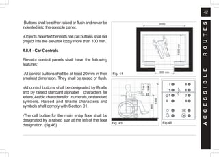
- Sound levels for alarm signals shall not exceed
120 dbA.
15.3 VISUAL ALARMS
- Visual alarm signal appliances shall be
integrated into the building or facility alarm
system. If single station audible alarms are
provided then single station visual alarm signals
shall be provided.
- Visual alarm signals shall have the following
minimum photometric and location features:
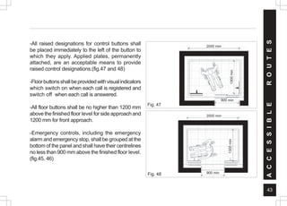
- 1.The lamp shall be a xenon strobe type or
equivalent.
- 2.The colour shall be clear or nominal white
(i.e.unfiltered or clear filtered white light)
- 3. The maximum pulse duration shall be two-
tenths of one second [0.2 sec] with a maximum
duty cycle of 40 per cent. The pulse duration is
defined as the time interval between initial and
final points of 10 per cent of maximum signal.
- 4.The intensity shall be a minimum of 75
candelas.](https://image.slidesharecdn.com/barrier-free-built-environment-220329173902/85/barrier-free-built-environment-pdf-104-320.jpg)
![86
A
L
A
R
M
S
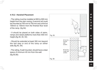
- 5. The flash rate shall be a minimum of 1 Hz
and a maximum of 3 Hz.
- 6. The appliance shall be placed 2000 mm
above the highest floor level within the space,
or 150 mm below the ceiling, whichever is lower.
- 7. In general, no place in any room or space
required to have a visual signal appliance shall
be more than 15 mts from the signal [in horizontal
plane]. In large rooms and spaces exceeding 30
mts across, without obstructions 2 mts above
the finished floor level, such as auditoriums,
devices may be placed around the perimeter,
spaced a maximum 30 mts apart, in lieu of
suspending appliances from the ceiling.
- 8. No place in common corridors or hallways in
which visual alarm signalling appliances are
required shall be more than 15 mts from the
signal.
15.4 AUXILIARY ALARMS
- Units and sleeping accommodations shall have
a visual alarm connected to the building
emergency alarm system or shall have a
standard 110-volt electrical receptacle into which
such an alarm can be connected and a means
by which a signal from the building emergency
alarm system can trigger such an auxiliary alarm.
When visual alarms are in place, the signal shall
be visible in all areas of the unit or room.
Instructions for use of the auxiliary alarm or
receptacle shall be provided.](https://image.slidesharecdn.com/barrier-free-built-environment-220329173902/85/barrier-free-built-environment-pdf-105-320.jpg)


![74676371-Coagulation-and-Flocculation[1].ppt](https://cdn.slidesharecdn.com/ss_thumbnails/74676371-coagulation-and-flocculation1-260116154109-a3cbf55e-thumbnail.jpg?width=640&height=640&fit=bounds)


