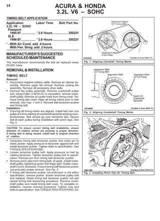
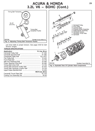
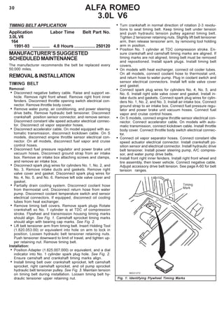
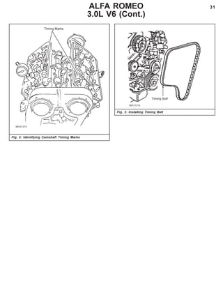
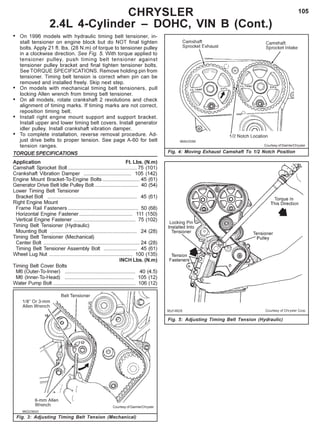
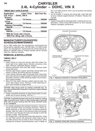
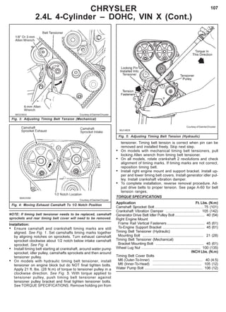
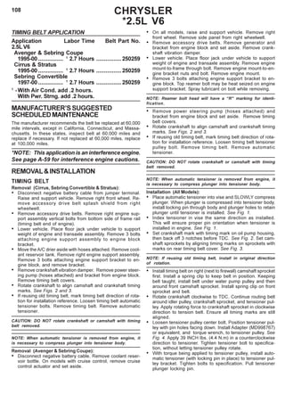
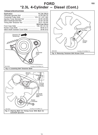
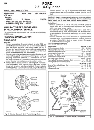
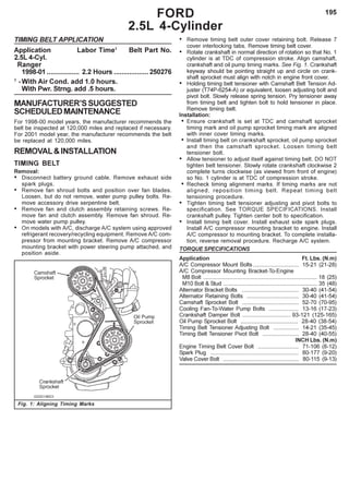
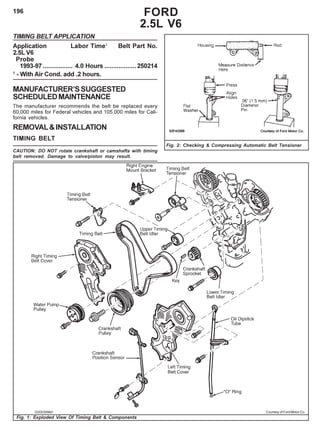
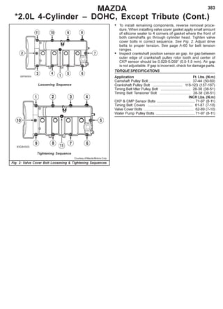
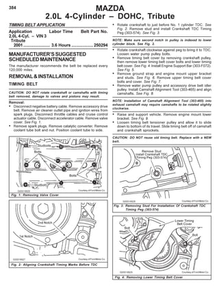
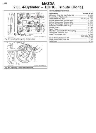
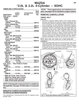
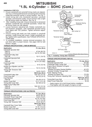
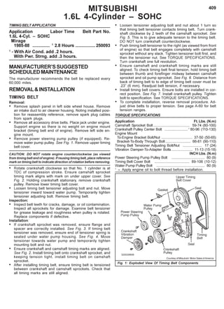
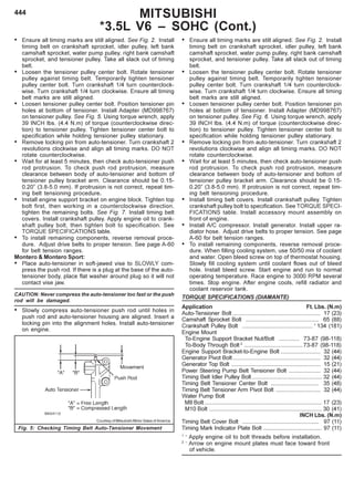
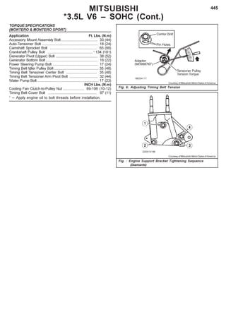
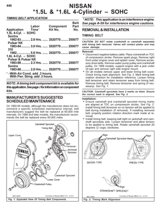
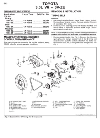
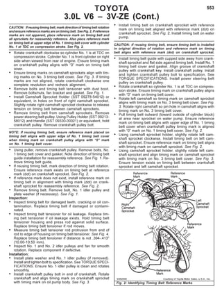
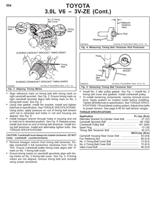
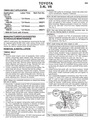
Download to read offline

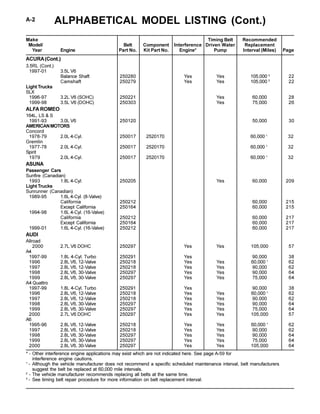
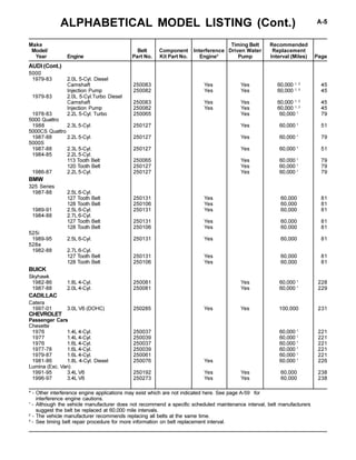
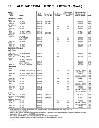
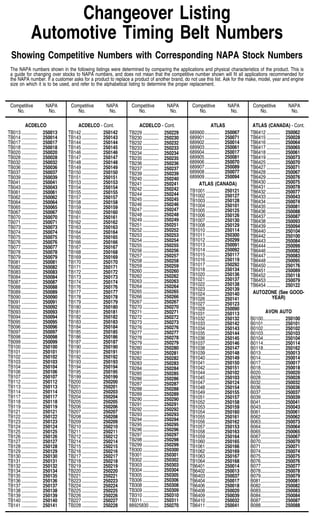
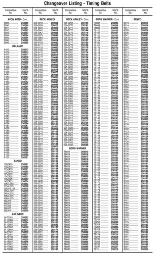
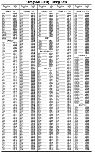
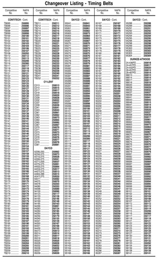
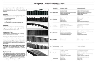
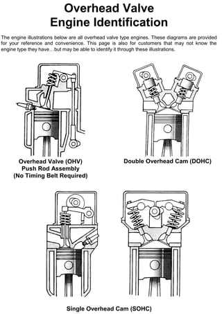
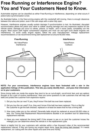
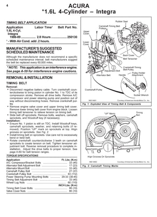
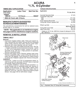
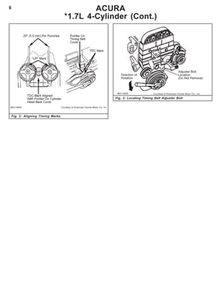
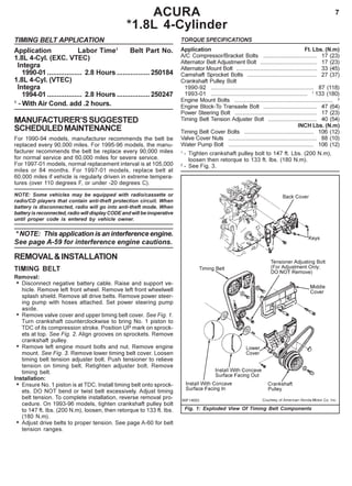

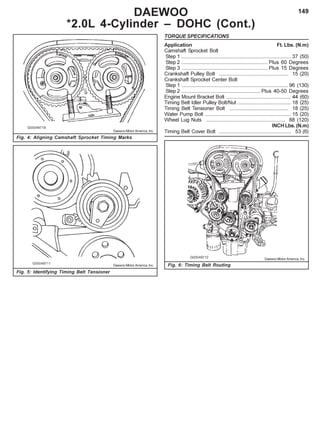
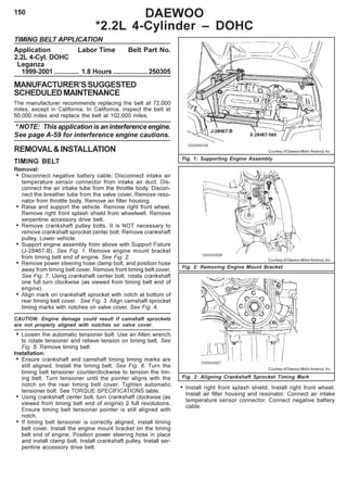
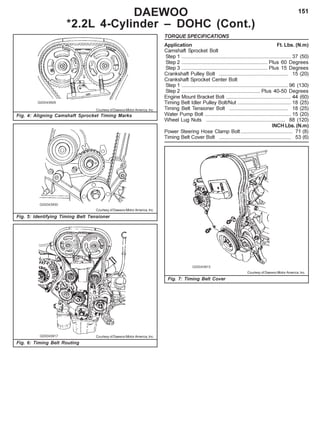
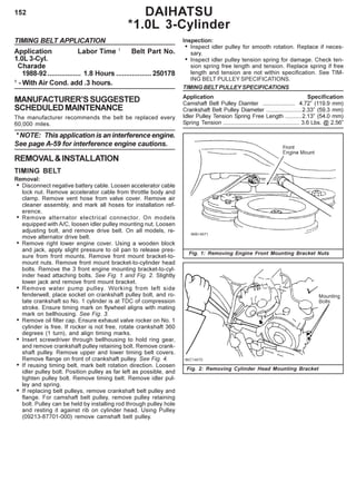
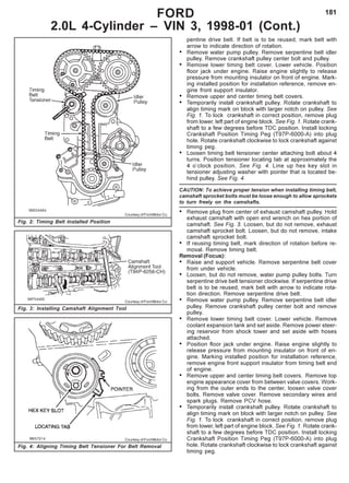
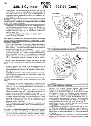
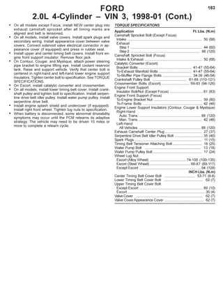
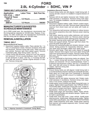


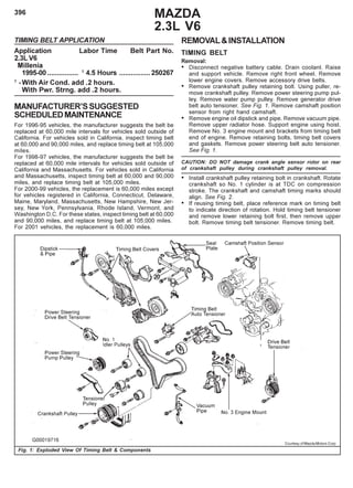
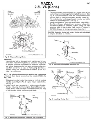
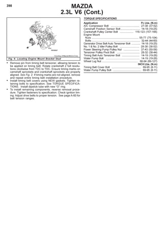
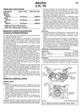


This document provides information about timing component kits, including: - Timing component kits contain all necessary parts (belt, tensioner, idler) for replacing the timing belt system to avoid warranty issues from worn parts. - NAPA timing component kits include OE quality parts and installation instructions specific to each vehicle application. - The document discusses different timing belt tooth profiles, materials like HSN, and why complete replacement is recommended over just replacing the belt. - Tables list timing belt replacement intervals for various Acura and Honda models.