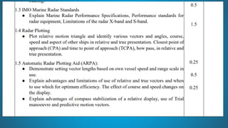
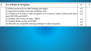
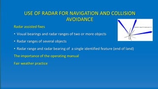
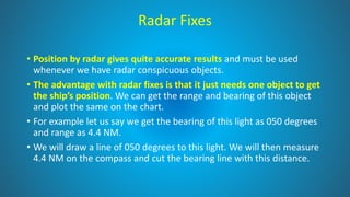
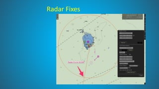
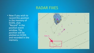
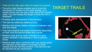
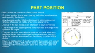
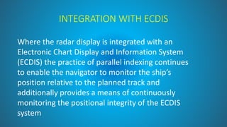
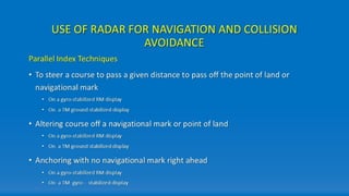
BRIDGE EQUIPMENT AND WATCH KEEPING
BSC IIIYEAR
SEM V– PAPER II
UNIT 2 – THE USE OF RADAR IN NAVIGATION
SYLLABUS
`
USE OF RADAR IN NAVIGATION
Radar Fixes
• Position by radar gives quite accurate results and must be used
whenever we have radar conspicuous objects.
• The advantage with radar fixes is that it just needs one object to get
the ship’s position. We can get the range and bearing of this object
and plot the same on the chart.
• For example let us say we get the bearing of this light as 050 degrees
and range as 4.4 NM.
• We will draw a line of 050 degrees to this light. We will then measure
4.4 NM on the compass and cut the bearing line with this distance.
Radar Fixes
• In the same way, if you have two objects, you can plot the radar fix by
number of combinations of position lines like
• bearings of these two objects
• bearing of one object and range of other object
• range of both objects
• As more and more ships are moving to the paperless navigation, we
must know how to fix the ship’s position by radar on ECDIS.
Radar Fixes
• So let us fix the ship’s position on
Furuno ECDIS.
• Let us say for this island, we get a
bearing of 010 Degrees and
distance 2.5NM from the radar.
• On Furuno ECDIS go to Record ->
This will open a position event
window. Choose LOP and then
choose True-bearing + Distance
option.
Radar Fixes
• Now click on the point of the
island for which the bearing and
distance were taken from the
radar.
• Now enter the bearing and
distance in the position event
window and then click “Add”.
Radar Fixes
• Now click on the point of the
island for which the bearing and
distance were taken from the
radar.
• Now enter the bearing and
distance in the position event
window and then click “Add”.
• This will give you your position.
Radar Fixes
RADAR FIXES
• Now if you wish to
record this position
in the memory of
ECDIS, click
“Record” in the
position event
window. The
position will be
plotted on ECDIS
and recorded in the
memory.
RADAR FIXES
• If we have two bearings (or two range) of two objects, the
process of plotting radar fix on ECDIS is same as above.
Just instead of “bearing + Distance”, choose “bearing” (or
distance) option.
TARGET TRAILS
• Trails are the after glow after the target has passed
• The echo trails feature enables you to track the
movement of vessels on the radar display. As a
vessel moves, you can see a faint trail of the vessel's
wake. You can change the length of time the trail is
displayed.
• Enables early assessment of the situation.
• The trail can either be relative or true.
• Relative trail shows relative movement between own
ship and target.
• True trail presents true target movements depending
on their over the ground speed and course.
• Relative trails give an early indication if a close
quarter situation is developing or risk of collision
exists.
• Relative trails when combined with true vectors gives
an indication of the relative movement of other
vessels and the risk they present. The trail time can
be adjusted as per requirement.
PAST POSITION
• History dots are placed at a fixed preset interval.
• Dots in a straight line at even spacing indicate a steady course
and speed by the targets.
• Any changes can be noted as the spacing becomes uneven.
Change of course will not be shown in a straight line.
• A curve in the trail indicates an alteration of course whereas
• The change in the spacing of the plots indicates a change in the
speed of the target.
• The past data can also help the observer to check whether a
particular target has maneuvered in the recent past, possibly
while the observer was away from the display on other bridge
duties.
• However past position, if used can clutter the screen and should
be avoided in heavy traffic as the plots of different targets start
crossing and overlapping each other and should be used with
caution.
VECTOR MODE
• Target vectors CAN BE SET relative to own ship’s heading (RELATIVE) or North (TRUE)
• When determining close quarter situation or risk of collision exist use of relative
vectors is preferred.
• It is a good practice to switch between true and relative vectors to gain a better
appreciation of the navigational situation
• When using a true vector, own ship and other ship moves at their true speed and course.
True vectors can distinguish between moving and stationary targets.
• The relative vector helps to find ships on a collision course. A ship whose vector
passes through own ship’s position is on a collision course.
• The Vector Length can be adjusted to the required time frame.
• It is useful to have both relative and true information visible simultaneously; this
can be achieved by selecting relative vectors with true trails.
• Combining true vectors with true trails will give no indication of the relative movement of
other vessels and the risk they present. Shift the cursor to vector mode box and left click
to select the vector required. The vector time can also be selected using the left button.
•
RACON, RAMARK, BEACONS
• Radar beacons are transmitters designed to produce a distinctive image on the screens
of ships' radar sets, thus enabling the mariner to determine his position with greater
certainty than would be possible by means of a normal radar display alone.
• Many Lighthouse Authorities have established radar beacons, usually of the type known
as Racons, at lighthouses and at other sites where it is believed they would give good
service to shipping.
• When it is known, the nominal range of a Racon is included in the details of the beacon.
• The range of reception of a Racon response depends upon the power of the Racon and
the interrogating radar set and also the height of the Racon and the radar antenna.
• Low powered radar sets may not be capable of triggering a response from a Racon and
some Racon responses may be too weak to reach the triggering radar set.
RACON, RAMARK, BEACONS
RACON
• A radar transponder beacon which emits a
characteristic signal when triggered by
emissions of ships' radars.
• All Racons at present fully operational are in-
band Racons i.e. they respond within the
frequency range of the marine radar band.
• The majority of in-band Racons are of the swept
frequency type; i.e, the transponder frequency
sweeps the frequency range of the marine radar
band.
• The Racon response to a ship's triggering radar
pulse will therefore appear automatically on the
ship's radar display for the period when the
Racon sweep is within the bandwidth of the
ship's radar receiver.
RACON
• They may cease to respond for a few seconds each
minute to allow radar echoes otherwise obscured by
the Racon signal to be distinguished;
• at other times the Racon response appears
automatically on the ship's radar display.
• The majority of Racons respond to 3cm (X-band) and
10 cm (S-band) radar emissions. The 3cm (X-band)
operates between 9300 and 9500 MHz. The 10 cm
(S-band) operates between 2900 and 3100 MHz.
• Except where otherwise indicated, the "Racon flash"
takes the form of a single line or narrow sector,
extending radially towards the circumference of the
radar display, from a point slightly beyond the spot (if
any) formed by the echo from the lighthouse, etc, at
the Racon site.
RACON
• The chart symbol for a racon is a magenta circle with
Racon written next to it, normally the Morse Code letter
that the racon transmits is included. Letters that consist
of mainly dashes tend to be used as ones made up of
only dots could be confused with other targets on the
screen more easily.
• New, temporary and uncharted hazards are often
marked by a buoy with a racon that transmits the letter
"D" in the morse code, dash dot dot (-..)
• As with all navigation techniques, using the radar to fix
your position from the range of charted objects must be
practiced in easy conditions before you rely on it at night
or in poor visibility.
• Thus, "distance off" may be measured to the point at which
the Racon flash begins but the figure obtained will be greater
than the ship's distance from the Racon; this is due to the
slight response delay in the radar beacon apparatus.
Ramark
• A ramark is a radar beacon which transmits either
continuously or at intervals.
• The latter method of transmission is used so that the PPI
can be inspected without any clutter introduced by the
ramark signal on the scope.
• The ramark signal as it appears on the PPI is a radial line
from the center. It gives only bearing
• The radial line may be a continuous narrow line, a broken
line , a series of dots, or a series of dots and dashes.
Search and Rescue Radar Transponder
(SART)
Radar screen from a
SART on a distance of
more than 5 miles.
A SART has a receiver that detects the signals from X-
band radars (92 - 9.5 GHz) if within a range of 8 NM.
If the SART detects a signal it immediately transmits
twelve pulses on the same frequency. This signal is seen
by the radar as "echoes" and will be displayed on the screen
as a series of twelve dots with a gap of 0.6 miles between
them. The first dot is at the position of the SART and the
others go in a straight line towards the edge of the screen.
If the rescue vessel approaches the SART, the twelve dots
will become short arcs. These arcs increase in size if the
vessel gets closer. If the rescue vessel is very close, the
SART will be activated permanently by the side lobes of the
radar antenna. The signal of the SART will then be visible as
twelve complete circles on the radar screen. This will tell the
search-and-rescue team that they have more or less arrived.
RADAR IMAGE OVERLAY ON ECDIS
• Radar overlay (a raw radar image overlaid on an electronic
chart) is the best means of verifying cartographic data and
the output of navigation sensors.
• The radar overlay feature of an ECDIS not only duplicates the
radar itself, as some navigators know, but can also be used to
verify the entire navigational system.
RADAR IMAGE OVERLAY ON ECDIS
The orientation, heading alignment and scale should be correct
The OOW can check these factors by confirming that the radar image
correlates with charted deaturers
Adjust the colour and transparency of RIO to ensure that radar contacts
can be clearly viewed on ECDIS without obscuring charted features
RIO is not a substitute for maintaining an anti-collision plot on a separate
radar/ ARPA display
AIS OVERLAY ON RADAR
• Radar and AIS data can be very effective if used together, either manually
or automatically (association). AIS data can be made to over lay on
Radar/ARPA/ ECDIS
• Benefits and weaknesses of operating radar and AIS together include:
• Two independent ways of detecting targets
• Two independent estimates of a target’s range, bearing, course and speed
• Radar detection of targets that do not carry AIS
• Clear AIS transmissions, almost unaffected by clutter AIS can be ‘seen’, whereas
radar detection can be impossible, e.g. behind islands and headlands
• Radar doesn’t have to rely on external data sources, unlike AIS
• AIS can indicate changes in course and speed quicker than radar can detect them
• AIS can often provide more information about a target
AIS TARGETS ON ARPA
• Radar / ARPA systems are able to display AIS target information
alongside or merged with ARPA information if connected to the AIS
transponder onboard
• The ARPA display should clearly indicate whether the target
information comes from ARPA or AIS
• AIS information, particularly CPA and TCPA should not be relied
upon for collision avoidance
`
PARALLEL INDEX TECHNIQUE
✓The running of a parallel index line
provides real time information on
the ship’s lateral position relative
to the planned track
✓ On the chart a line is drawn from
the edge of a radar conspicuous
object, parallel to the planned track
✓The perpendicular distance (or
cross- index range) from the object
to the track is then measured
✓The range strobe on the radar is
then set to this range, and a solid
china graph line drawn on the
display parallel to the planned
course on a scale appropriate to the
range in use
PARALLEL INDEX TECHNIQUE
• Positions 1, 2 and 3 on the chart and
radar display show the ship on track
at various instances up to the time
that the island is abeam to
starboard.
• Positions 4 and 5 show the ship off
track to port. The exact distance off
track can be measured by dividers
from the radar echo of the island to
the nearest point of the parallel
index line
PARALLEL INDEXING ON A RELATIVE MOTION
DISPLAY
• On a relative motion compass-stabilised radar display, the echo of a fixed
object will move across the display in a direction and at a speed which is
the exact reciprocal of own ship’s ground track: parallel indexing uses this
principle of relative motion.
• Reference is first made to the chart and the planned ground track. The
index line is drawn parallel to the planned ground track at a perpendicular
distance (cross index range or offset) equal to the planned passing distance
off an appropriate fixed target.
• Observation of the fixed object’s echo movement along the index line will
indicate whether the ship is maintaining the planned track: any
displacement of the echo from the index line will immediately indicate that
own ship is not maintaining the desired ground track, enabling corrective
action to be taken.
PARALLEL INDEXING ON A TRUE MOTION
DISPLAY
• The use of a true motion radar presentation for parallel indexing requires
an ability to ground stabilise the display reliably.
• Parallel index lines are fixed relative to the trace origin (i.e. to own ship),
and consequently move across the display at the same rate and in the
same direction as own ship.
• Being drawn parallel to the planned charted track and offset at the
required passing distance off the selected fixed mark, the echo of the mark
will move along the index line as long as the ship remains on track.
• Any displacement of the fixed mark’s echo from the index line will indicate
that the ship is off track, enabling corrective action to be taken
INTEGRATION WITH ECDIS
Where the radar display is integrated with an
Electronic Chart Display and Information System
(ECDIS) the practice of parallel indexing continues
to enable the navigator to monitor the ship’s
position relative to the planned track and
additionally provides a means of continuously
monitoring the positional integrity of the ECDIS
system
b REVISED UNIT 2.pdbbibibibfiviviviuvuvivuv

b REVISED UNIT 2.pdbbibibibfiviviviuvuvivuv

  • 1.
    BRIDGE EQUIPMENT ANDWATCH KEEPING BSC IIIYEAR SEM V– PAPER II UNIT 2 – THE USE OF RADAR IN NAVIGATION
  • 2.
  • 4.
  • 12.
    USE OF RADARIN NAVIGATION
  • 14.
    Radar Fixes • Positionby radar gives quite accurate results and must be used whenever we have radar conspicuous objects. • The advantage with radar fixes is that it just needs one object to get the ship’s position. We can get the range and bearing of this object and plot the same on the chart. • For example let us say we get the bearing of this light as 050 degrees and range as 4.4 NM. • We will draw a line of 050 degrees to this light. We will then measure 4.4 NM on the compass and cut the bearing line with this distance.
  • 15.
    Radar Fixes • Inthe same way, if you have two objects, you can plot the radar fix by number of combinations of position lines like • bearings of these two objects • bearing of one object and range of other object • range of both objects • As more and more ships are moving to the paperless navigation, we must know how to fix the ship’s position by radar on ECDIS.
  • 16.
    Radar Fixes • Solet us fix the ship’s position on Furuno ECDIS. • Let us say for this island, we get a bearing of 010 Degrees and distance 2.5NM from the radar. • On Furuno ECDIS go to Record -> This will open a position event window. Choose LOP and then choose True-bearing + Distance option.
  • 17.
    Radar Fixes • Nowclick on the point of the island for which the bearing and distance were taken from the radar. • Now enter the bearing and distance in the position event window and then click “Add”.
  • 18.
    Radar Fixes • Nowclick on the point of the island for which the bearing and distance were taken from the radar. • Now enter the bearing and distance in the position event window and then click “Add”. • This will give you your position.
  • 19.
  • 20.
    RADAR FIXES • Nowif you wish to record this position in the memory of ECDIS, click “Record” in the position event window. The position will be plotted on ECDIS and recorded in the memory.
  • 21.
    RADAR FIXES • Ifwe have two bearings (or two range) of two objects, the process of plotting radar fix on ECDIS is same as above. Just instead of “bearing + Distance”, choose “bearing” (or distance) option.
  • 22.
    TARGET TRAILS • Trailsare the after glow after the target has passed • The echo trails feature enables you to track the movement of vessels on the radar display. As a vessel moves, you can see a faint trail of the vessel's wake. You can change the length of time the trail is displayed. • Enables early assessment of the situation. • The trail can either be relative or true. • Relative trail shows relative movement between own ship and target. • True trail presents true target movements depending on their over the ground speed and course. • Relative trails give an early indication if a close quarter situation is developing or risk of collision exists. • Relative trails when combined with true vectors gives an indication of the relative movement of other vessels and the risk they present. The trail time can be adjusted as per requirement.
  • 23.
    PAST POSITION • Historydots are placed at a fixed preset interval. • Dots in a straight line at even spacing indicate a steady course and speed by the targets. • Any changes can be noted as the spacing becomes uneven. Change of course will not be shown in a straight line. • A curve in the trail indicates an alteration of course whereas • The change in the spacing of the plots indicates a change in the speed of the target. • The past data can also help the observer to check whether a particular target has maneuvered in the recent past, possibly while the observer was away from the display on other bridge duties. • However past position, if used can clutter the screen and should be avoided in heavy traffic as the plots of different targets start crossing and overlapping each other and should be used with caution.
  • 24.
    VECTOR MODE • Targetvectors CAN BE SET relative to own ship’s heading (RELATIVE) or North (TRUE) • When determining close quarter situation or risk of collision exist use of relative vectors is preferred. • It is a good practice to switch between true and relative vectors to gain a better appreciation of the navigational situation • When using a true vector, own ship and other ship moves at their true speed and course. True vectors can distinguish between moving and stationary targets. • The relative vector helps to find ships on a collision course. A ship whose vector passes through own ship’s position is on a collision course. • The Vector Length can be adjusted to the required time frame. • It is useful to have both relative and true information visible simultaneously; this can be achieved by selecting relative vectors with true trails. • Combining true vectors with true trails will give no indication of the relative movement of other vessels and the risk they present. Shift the cursor to vector mode box and left click to select the vector required. The vector time can also be selected using the left button. •
  • 25.
    RACON, RAMARK, BEACONS •Radar beacons are transmitters designed to produce a distinctive image on the screens of ships' radar sets, thus enabling the mariner to determine his position with greater certainty than would be possible by means of a normal radar display alone. • Many Lighthouse Authorities have established radar beacons, usually of the type known as Racons, at lighthouses and at other sites where it is believed they would give good service to shipping. • When it is known, the nominal range of a Racon is included in the details of the beacon. • The range of reception of a Racon response depends upon the power of the Racon and the interrogating radar set and also the height of the Racon and the radar antenna. • Low powered radar sets may not be capable of triggering a response from a Racon and some Racon responses may be too weak to reach the triggering radar set.
  • 26.
    RACON, RAMARK, BEACONS RACON •A radar transponder beacon which emits a characteristic signal when triggered by emissions of ships' radars. • All Racons at present fully operational are in- band Racons i.e. they respond within the frequency range of the marine radar band. • The majority of in-band Racons are of the swept frequency type; i.e, the transponder frequency sweeps the frequency range of the marine radar band. • The Racon response to a ship's triggering radar pulse will therefore appear automatically on the ship's radar display for the period when the Racon sweep is within the bandwidth of the ship's radar receiver.
  • 27.
    RACON • They maycease to respond for a few seconds each minute to allow radar echoes otherwise obscured by the Racon signal to be distinguished; • at other times the Racon response appears automatically on the ship's radar display. • The majority of Racons respond to 3cm (X-band) and 10 cm (S-band) radar emissions. The 3cm (X-band) operates between 9300 and 9500 MHz. The 10 cm (S-band) operates between 2900 and 3100 MHz. • Except where otherwise indicated, the "Racon flash" takes the form of a single line or narrow sector, extending radially towards the circumference of the radar display, from a point slightly beyond the spot (if any) formed by the echo from the lighthouse, etc, at the Racon site.
  • 28.
    RACON • The chartsymbol for a racon is a magenta circle with Racon written next to it, normally the Morse Code letter that the racon transmits is included. Letters that consist of mainly dashes tend to be used as ones made up of only dots could be confused with other targets on the screen more easily. • New, temporary and uncharted hazards are often marked by a buoy with a racon that transmits the letter "D" in the morse code, dash dot dot (-..) • As with all navigation techniques, using the radar to fix your position from the range of charted objects must be practiced in easy conditions before you rely on it at night or in poor visibility. • Thus, "distance off" may be measured to the point at which the Racon flash begins but the figure obtained will be greater than the ship's distance from the Racon; this is due to the slight response delay in the radar beacon apparatus.
  • 29.
    Ramark • A ramarkis a radar beacon which transmits either continuously or at intervals. • The latter method of transmission is used so that the PPI can be inspected without any clutter introduced by the ramark signal on the scope. • The ramark signal as it appears on the PPI is a radial line from the center. It gives only bearing • The radial line may be a continuous narrow line, a broken line , a series of dots, or a series of dots and dashes.
  • 30.
    Search and RescueRadar Transponder (SART) Radar screen from a SART on a distance of more than 5 miles. A SART has a receiver that detects the signals from X- band radars (92 - 9.5 GHz) if within a range of 8 NM. If the SART detects a signal it immediately transmits twelve pulses on the same frequency. This signal is seen by the radar as "echoes" and will be displayed on the screen as a series of twelve dots with a gap of 0.6 miles between them. The first dot is at the position of the SART and the others go in a straight line towards the edge of the screen. If the rescue vessel approaches the SART, the twelve dots will become short arcs. These arcs increase in size if the vessel gets closer. If the rescue vessel is very close, the SART will be activated permanently by the side lobes of the radar antenna. The signal of the SART will then be visible as twelve complete circles on the radar screen. This will tell the search-and-rescue team that they have more or less arrived.
  • 31.
    RADAR IMAGE OVERLAYON ECDIS • Radar overlay (a raw radar image overlaid on an electronic chart) is the best means of verifying cartographic data and the output of navigation sensors. • The radar overlay feature of an ECDIS not only duplicates the radar itself, as some navigators know, but can also be used to verify the entire navigational system.
  • 32.
    RADAR IMAGE OVERLAYON ECDIS The orientation, heading alignment and scale should be correct The OOW can check these factors by confirming that the radar image correlates with charted deaturers Adjust the colour and transparency of RIO to ensure that radar contacts can be clearly viewed on ECDIS without obscuring charted features RIO is not a substitute for maintaining an anti-collision plot on a separate radar/ ARPA display
  • 33.
    AIS OVERLAY ONRADAR • Radar and AIS data can be very effective if used together, either manually or automatically (association). AIS data can be made to over lay on Radar/ARPA/ ECDIS • Benefits and weaknesses of operating radar and AIS together include: • Two independent ways of detecting targets • Two independent estimates of a target’s range, bearing, course and speed • Radar detection of targets that do not carry AIS • Clear AIS transmissions, almost unaffected by clutter AIS can be ‘seen’, whereas radar detection can be impossible, e.g. behind islands and headlands • Radar doesn’t have to rely on external data sources, unlike AIS • AIS can indicate changes in course and speed quicker than radar can detect them • AIS can often provide more information about a target
  • 34.
    AIS TARGETS ONARPA • Radar / ARPA systems are able to display AIS target information alongside or merged with ARPA information if connected to the AIS transponder onboard • The ARPA display should clearly indicate whether the target information comes from ARPA or AIS • AIS information, particularly CPA and TCPA should not be relied upon for collision avoidance
  • 35.
  • 36.
    PARALLEL INDEX TECHNIQUE ✓Therunning of a parallel index line provides real time information on the ship’s lateral position relative to the planned track ✓ On the chart a line is drawn from the edge of a radar conspicuous object, parallel to the planned track ✓The perpendicular distance (or cross- index range) from the object to the track is then measured ✓The range strobe on the radar is then set to this range, and a solid china graph line drawn on the display parallel to the planned course on a scale appropriate to the range in use
  • 37.
    PARALLEL INDEX TECHNIQUE •Positions 1, 2 and 3 on the chart and radar display show the ship on track at various instances up to the time that the island is abeam to starboard. • Positions 4 and 5 show the ship off track to port. The exact distance off track can be measured by dividers from the radar echo of the island to the nearest point of the parallel index line
  • 38.
    PARALLEL INDEXING ONA RELATIVE MOTION DISPLAY • On a relative motion compass-stabilised radar display, the echo of a fixed object will move across the display in a direction and at a speed which is the exact reciprocal of own ship’s ground track: parallel indexing uses this principle of relative motion. • Reference is first made to the chart and the planned ground track. The index line is drawn parallel to the planned ground track at a perpendicular distance (cross index range or offset) equal to the planned passing distance off an appropriate fixed target. • Observation of the fixed object’s echo movement along the index line will indicate whether the ship is maintaining the planned track: any displacement of the echo from the index line will immediately indicate that own ship is not maintaining the desired ground track, enabling corrective action to be taken.
  • 39.
    PARALLEL INDEXING ONA TRUE MOTION DISPLAY • The use of a true motion radar presentation for parallel indexing requires an ability to ground stabilise the display reliably. • Parallel index lines are fixed relative to the trace origin (i.e. to own ship), and consequently move across the display at the same rate and in the same direction as own ship. • Being drawn parallel to the planned charted track and offset at the required passing distance off the selected fixed mark, the echo of the mark will move along the index line as long as the ship remains on track. • Any displacement of the fixed mark’s echo from the index line will indicate that the ship is off track, enabling corrective action to be taken
  • 42.
    INTEGRATION WITH ECDIS Wherethe radar display is integrated with an Electronic Chart Display and Information System (ECDIS) the practice of parallel indexing continues to enable the navigator to monitor the ship’s position relative to the planned track and additionally provides a means of continuously monitoring the positional integrity of the ECDIS system