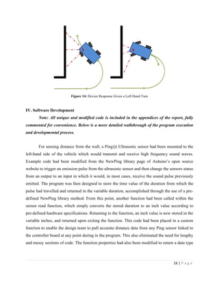
This document describes an autonomous vehicle project undertaken by a team of students. The team modified a remote control truck to navigate hallways and avoid obstacles autonomously using an Arduino microcontroller. The vehicle uses ultrasonic sensors for obstacle detection and PID control to follow walls at a set distance. The team developed software for wall following and obstacle avoidance behaviors to enable the vehicle to maneuver autonomously.
![4 | P a g e
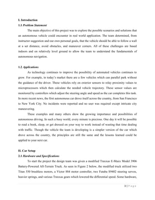
such as the radio receiver and the shifting servo, were removed due to their irrelevance to the
project. More detailed pictures of these individual components can be found in Appendix X.
Figure 1: Original E-Maxx Factory Configuration [1]
Figure 2: Modified E-Maxx Configuration
Of the mentioned truck components, the motor controller and the steering servos affect
the wall following capabilities of the device the most. Thus, in order for the microprocessor to
precisely maneuver the vehicle, the limitation of these components needed to be taken into
consideration. The specifications and limitations of each component are shown below.
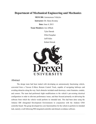
Table 1: Victor 884 Factory Specifications [2]](https://image.slidesharecdn.com/3fc72883-be94-4750-b5e1-2e4f4c9de1cd-151006032905-lva1-app6892/85/Autonomous-Vehicles-Project-5-320.jpg)
![5 | P a g e
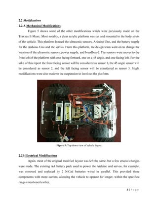
Table 2: Futaba S9402 Factory Specifications [3]
The team, for instance, needed to make sure that the proper operating voltage was
supplied to both the controller and the cooling fan. This was done through a new wiring setup
which will be explained in section 2.2A. Another concern was limiting the amount of current
sent to the motor controller. The batteries and microprocessor used in this project are well within
these component’s limits. As for moving the vehicle, the team wanted to keep the device at a
relatively slow pace. However, the team did have to maintain a speed greater than 5.4% of the
controller’s maximum value. This pace was determined through trial and error of analog values,
which will be explained in section 4.1.
Moving onto the control system, the main components consisted of an Arduino Uno and
three ping ultrasonic distance sensors from Parallax. The Arduino Uno is a fairly inexpensive
microprocessor which has some great features that can be seen in the table below. From a design
standpoint, the team was mainly concerned with the operating voltage, input voltage limits, and
the DC current output to the pins. As shown in Tables 3 and 4, the output voltages or currents do
not interfere with any of the other parts. The Arduino Uno also has the capability of sending
analog signals required by the servos. One feature which the team did not get to utilize was the
Arduino’s interrupts which were originally going to be used for the obstacle avoidance routine
explained in section 3.2.
Parameter Value
Nominal Voltage 12V
Min/Max Voltage 6V - 15V
Continous Current 60 A
Surge Current 150 A
Nominal PWMInput Pulse (high time) 1-2 miliseconds
Min/Max PWMInput Pulse (high time) .87-2.14 miliseconds
PWMInput Rate (period) 2.1 - 500 miliseconds
PWMOutput Chop Rate 1 KHz
Minimum Throttle 5.40%
Fan Voltage Range 6V - 16V
Parameter Value
Input Signal Analog
Nominal Voltage 6V
Maximum Torque 111 oz-in](https://image.slidesharecdn.com/3fc72883-be94-4750-b5e1-2e4f4c9de1cd-151006032905-lva1-app6892/85/Autonomous-Vehicles-Project-6-320.jpg)
![6 | P a g e
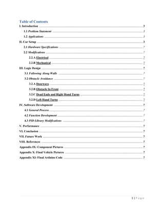
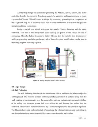
Table 3: Arduino Uno Factory Specifications [4]
Table 4: Ultrasonic Sensor Factory Specifications [5]
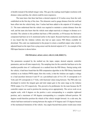
The second component of the control system was the ultrasonic sensors. These sensors
work by recording the time it takes a sound wave to hit an object and then return to the sensor.
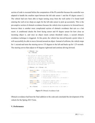
Given the sensors pulse speed, the distance between the object and the sensor can be calculated
via D = V*(T/2). Some important limitations of these sensors include the minimum and
maximum sensing distances, the field pattern, and the maximum reading angle of 45. As shown
in Figure 3, at angles greater than 45 the sound waves bounce off of oncoming objects and travel
further away from the sensor. This returns an inaccurate distance value that is equal to the
sensors maximum, three meters. Considering the distance limits of the sensor, the team chose a
wall following distance well within this range of 18 inches.
Parameter Value
Operating Voltage 5V
Nominal Input Voltage 7V - 12V
Input Voltage (limits) 6V - 20V
# Digital I/O Pins 14
# Digital Pins w/ PWMOutput 6
# Interupt Pins 2
# Analog Input Pins 6
DC Current I/O Pins 40 mA
DC Current 3.3V Pin 50 mA
Flash Memory 32 KB
SRAM 2 KB
EEPROM 1 KB
Clock Speed 16 MHz
Parameter Value
Sensing Range 2cm - 3m
Operating Voltage 5V
Nominal Operating Current 30 mA
Maximum Operating Current 35 mA
Nominal PWMInput Pulse (high time) 2 miliseconds
Maximum PWMInput Pulse (high time) 5 miliseconds](https://image.slidesharecdn.com/3fc72883-be94-4750-b5e1-2e4f4c9de1cd-151006032905-lva1-app6892/85/Autonomous-Vehicles-Project-7-320.jpg)
![7 | P a g e
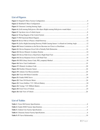
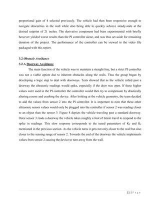
Figure 3: Ultrasonic Limiting Sensing Angle [5]
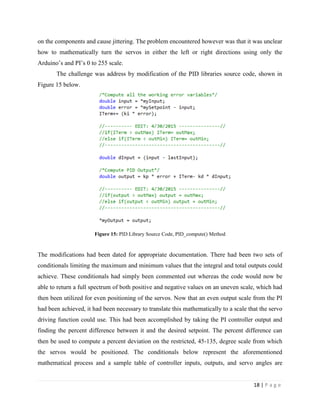
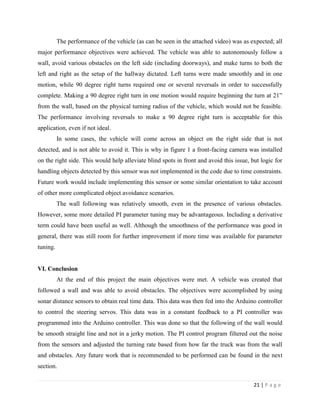
Though this cannot be avoided, another issue is the sensors inability to read certain
objects. As seen in Figure 4, the sensor has the ability to read flat objects, parallel to the sensor,
better than round objects. This is because the sound waves bounce off of round objects in
varying directions. Thus the field of sensing becomes wider but the maximum distance the
sensor can read is lessened. Most of the testing performed utilized flat objects such as walls,
boxes, doors, etc.
Figure 4: (Left) sensing field given a flat object (Right) sensing field given a round object [5]
Lastly, the batteries used for this project were 7.2V 6-cell rechargeable NiCd batteries
and Turnigy 5000mAh 2SIP 7.4V 30C batteries. The NiCd batteries were used to power the
Arduino and the servos while the more powerful Turnigy batteries were used to power the
motors.](https://image.slidesharecdn.com/3fc72883-be94-4750-b5e1-2e4f4c9de1cd-151006032905-lva1-app6892/85/Autonomous-Vehicles-Project-8-320.jpg)
![10 | P a g e
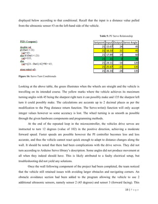
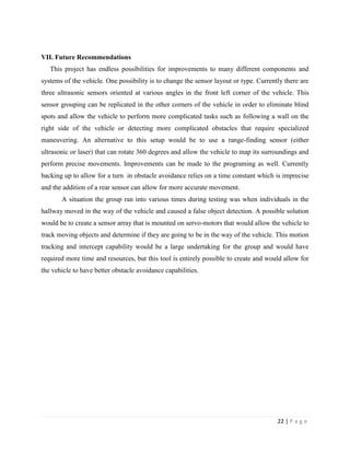
Simply stated, a PI controller, a variation of the PID controller, calculates the error
between a measured process variable and a defined setpoint, and then attempts to minimize the
error by adjusting the process variable via a feedback loop. The controller utilizes 3 unique
constant parameters to perform the aforementioned task, namely the proportional, integral, and
derivative gains. In layman’s terms, the proportional component is calculated based on present
error, the integral component is based on the accumulation of past errors, and the derivative
component is based on the prediction of future errors [6]. A block diagram schematic is shown
below to illustrate the feedback and process.
Figure 7: PID Functional Block Diagram [6]
There a variety of ways to tune the parameters of PID controller to obtain a desired
response. Several involve mathematical calculations as per the equations shown in the above
figure. For this project, the design team had opted to use a manual tuning method via software
implementation. Following correct setup of the code, to be explained later, each parameter had
been tuned individually, first starting with the proportional gain. This value was increased from
its default value of 0 by increments of 1 until the team began to see oscillations in the vehicles
trajectory at a proportional gain of 4. From here, the integral component had been adjusted in a
similar fashion beginning with 1. This however produced a response that appeared to “ignore”
almost all inconsistencies in the wall that the vehicle had been using to gauge its distance,
rending the vehicle highly unresponsive. Values lower than 1 had been implemented in the
software controller, achieving more and more immediate results to variations in the walls of the
hallway. A value of 0.5 for the integral component had been used in conjunction with](https://image.slidesharecdn.com/3fc72883-be94-4750-b5e1-2e4f4c9de1cd-151006032905-lva1-app6892/85/Autonomous-Vehicles-Project-11-320.jpg)
![23 | P a g e
VIII. References
[1] Traxxas.com, 'E-Maxx: 1/10 Scale Electric 4WD Monster Truck with TQi Traxxas Link
Enabled 2.4GHz Radio System | Traxxas', 2015. [Online]. Available:
https://traxxas.com/products/models/electric/39036emaxx?t=specs. [Accessed: 05- Jun- 2015].
[2] Vexrobotics.com, 'Victor 888 Motor Controller - VEX Robotics', 2015. [Online]. Available:
http://www.vexrobotics.com/217-2769.html. [Accessed: 05- Jun- 2015].
[3] Servodatabase.com, 'Futaba S9402 Servo Specifications and Reviews', 2015. [Online].
Available: http://www.servodatabase.com/servo/futaba/s9402. [Accessed: 05- Jun- 2015].
[4] Arduino.cc, 'Arduino - ArduinoBoardUno', 2015. [Online]. Available:
http://www.arduino.cc/en/Main/ArduinoBoardUno. [Accessed: 05- Jun- 2015].
[5] Parallax.com, 'PING))) Ultrasonic Distance Sensor | 28015 | Parallax Inc', 2015. [Online].
Available: https://www.parallax.com/product/28015. [Accessed: 05- Jun- 2015].
[6] Wikipedia, 'PID controller', 2015. [Online]. Available:
http://en.wikipedia.org/wiki/PID_controller. [Accessed: 05- Jun- 2015].
[7] Traxxas.com, 'Motor, Titan 12T (12-Turn, 550 size) | Traxxas', 2015. [Online]. Available:
https://traxxas.com/products/parts/motors/titan12T. [Accessed: 05- Jun- 2015].
[8] www3.towerhobbies.com, 'TowerHobbies.com |Tower Hobbies NiCd 6-Cell 7.2V 1500mAh
Stick Standard', 2015. [Online]. Available: http://www3.towerhobbies.com/cgi-
bin/wti0001p?I=LXJA83. [Accessed: 05- Jun- 2015].
[9] HobbyKing Store, 'Turnigy 5000mAh 2S1P 7.4v 30C Hardcase Pack (ROAR APPROVED)',
2015. [Online]. Available:
http://www.hobbyking.com/hobbyking/store/__21005__Turnigy_5000mAh_2S1P_7_4v_30C_H
ardcase_Pack_ROAR_APPROVED_.html. [Accessed: 05- Jun- 2015].](https://image.slidesharecdn.com/3fc72883-be94-4750-b5e1-2e4f4c9de1cd-151006032905-lva1-app6892/85/Autonomous-Vehicles-Project-24-320.jpg)
![24 | P a g e
[10] T. Eckel, 'Arduino Playground - NewPing Library', Playground.arduino.cc, 2015. [Online].
Available: http://playground.arduino.cc/Code/NewPing. [Accessed: 06- Jun- 2015].
[11] B. Beauregard, 'Arduino Playground - PIDLibrary', Playground.arduino.cc, 2015. [Online].
Available: http://playground.arduino.cc/Code/PIDLibrary. [Accessed: 06- Jun- 2015].
Appendix IX: Component Pictures
Figure 18: Parallax Ultrasonic Sensor [5] Figure 19: Arduino Uno Microcontroller [4]
Figure 20: Victor 884 Motor Controller [2] Figure 21: Futaba S9402 Servo [3]
Figure 22: Titan 550 Electric Motor [7] Figure 23: Tower Hobbies 7.2V 1500 mA Battery [8]](https://image.slidesharecdn.com/3fc72883-be94-4750-b5e1-2e4f4c9de1cd-151006032905-lva1-app6892/85/Autonomous-Vehicles-Project-25-320.jpg)
![25 | P a g e
Figure 24: Turnigy 7.4V 5000mA Battery [9]
Appendix X: Final Vehicle Pictures
Figure 25: Front View of Vehicle](https://image.slidesharecdn.com/3fc72883-be94-4750-b5e1-2e4f4c9de1cd-151006032905-lva1-app6892/85/Autonomous-Vehicles-Project-26-320.jpg)
![26 | P a g e
Figure 26: Side View of Vehicle
Appendix XI: Final Arduino Code
NewPing Library Credit [10]
PID Library Credit [11]
Sketch Code (Modified to Fit Word Document):
//----------------------------------------------------------------------------------------------------------------------------//
// Sketch: MEM380 ST Automated Vehicles
// Date: 6 June 2015
// Author: Tyler Darrah
// Contributors: Jon Affleck, Elliot Farquhar, Jeff Fuller, Robert Stricek
//
// Purpose: This program had been developed for an autonomous vehicle to navigate Drexel
// University hallways, with the additional functionality of avoiding obstacles such as
// small doorways, water fountains, and conduit.
//----------------------------------------------------------------------------------------------------------------------------//
//------------------------------------------------------Libraries-----------------------------------------------------------//
#include <PID_v1.h>
#include <NewPing.h>
#include <Servo.h>
Servo drive;
Servo steer;
//------------------------------------------------Variable Declarations-------------------------------------------------//
const int ping1 = 11; // Front Left sensor pin //
const int ping2 = 8; // 45 degree angled sensor pin //](https://image.slidesharecdn.com/3fc72883-be94-4750-b5e1-2e4f4c9de1cd-151006032905-lva1-app6892/85/Autonomous-Vehicles-Project-27-320.jpg)
![27 | P a g e
const int ping3 = 9; // Left-side forward mounted sensor pin //
const int ping4 = 10; // Front Right sensor pin // [UNUSED]
int SampleTime = 1; // Controller sampling time //
double FLread; // Create variable to store values for front left sensor //
double F45read; // Create variable to store values for 45 angled sensor //
//----------------------------------------------PID Controller Definition----------------------------------------------//
// Define PID variables // In1 will store values for the left-mounted Ping sensor //
double In1, Out1, Set1, In2, Out2, Set2;
// PID #1 parameters // Format (Input, Output, Setpoint, Kp, Ki, Kd, Mode) //
// Mode(DIRECT, MANUAL)// DIRECT = Controller on // MANUAL = Controller off //
PID PID1(&In1, &Out1, &Set1, 4.00, 0.5, 0.00, DIRECT);
//------------------------------------------------Function Prototypes---------------------------------------------------//
// Ping time-to-distance conversion function prototype //
// Modified to return variable type double //
double microsecondsToInches(double microseconds);
//Function prototype for reading a Ping sensor on any pin //
double Ping_Read(int sensor);
//--------------------------------------------Program Setup (to run once)---------------------------------------------//
void setup() {
// initialize serial communication:
Serial.begin(9600); // Serial window set, 9600 bit/s //
PID1.SetSampleTime(SampleTime); // Decrease sampling time for controller to 1ms //
steer.attach(4); // Attach steering servo to pin #4 //
drive.attach(6); // Attach driving servo to pin #6 //
Set1 = 21.0; // Setpoint 21 inches //
In1 = Ping_Read(ping3); // Read Ping sensor pin #9 (Left Front) and set to Input 1 //
PID1.SetMode(AUTOMATIC); // Set controller to function continuously //
}
//------------------------------------------Program Setup (to run continuously)--------------------------------------//
void loop()
{
In1 = Ping_Read(ping3); //Read-in a value from the PID sensor
FLread = Ping_Read(ping1); //Read-in a value from the front mounted sensor
F45read = Ping_Read(ping2); //Read-in a value from the 45 deg angled sensor
//---------------------------Avoidance--------------------------------//
/* The first section is a preliminary attempt
at avoiding the wall but still maintaining](https://image.slidesharecdn.com/3fc72883-be94-4750-b5e1-2e4f4c9de1cd-151006032905-lva1-app6892/85/Autonomous-Vehicles-Project-28-320.jpg)

![PLC Ladder Programming [Mechatronics]](https://cdn.slidesharecdn.com/ss_thumbnails/plc-ppt-snteli-200503070616-thumbnail.jpg?width=640&height=640&fit=bounds)


![PPT On IOT BasedAutomatic Bumper [Autosaved].pptx](https://cdn.slidesharecdn.com/ss_thumbnails/pptoniotbasedautomaticbumperautosaved-240315163352-7fb59c2d-thumbnail.jpg?width=640&height=640&fit=bounds)