Downloaded 24 times

![15
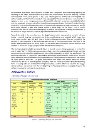
Overshooting
sequence:
Group
6
had
developed
a
feature
to
make
the
buggy
complete
the
track
in
a
more
reliable
way.
Overshooting
sequece
is
a
programming
feature
that
helps
the
buggy
to
take
sharp
turns
at
high
speeds.
This
feature
relies
on
the
fact
that
if
a
buggy
overshoots
a
line
at
the
corner,
the
last
sensor
sensing
the
line
would
have
been
one
of
the
end
sensors.
If
such
is
the
case,
the
buggy
would
try
to
rejoing
the
track
by
taking
a
sharp
turn
in
the
direction
depending
in
the
sensor
that
sensed
the
line.
If
,however,
any
of
the
middle
3
sensors
were
the
last
sensors
to
detect
the
line,
the
buggy
would
understand
that
it
has
reached
the
end
of
the
line
and
hence
would
stop.
8.0
Conclusion
The
buggy
was
able
to
achieve
most
of
its
aim
except
reaching
the
final
race.
It
was
capable
of
taking
turns
in
a
smooth
and
fast
way,
go
up
or
down
the
slope
while
maintaining
the
speed
and
stop
on
reaching
the
end
of
the
course.
The
total
cost
of
the
buggy
was
calculted
to
be
£32
including
recycable
items
which
is
underr
the
allocated
budget.
All
aims
were
accompilshed
while
abiding
by
the
regulations
of
maximum
6
sensors
and
budget
of
£50.
Many
new
innovative
features
such
as
RF
link
debugging
tool
and
ultrasound
sensor
not
only
eased
the
process
of
programming
but
also
improved
the
manoeuvrability
of
the
buggy
through
the
track.
During
the
two
heats,
group
6
had
mixed
fortunes.
For
the
first
heat,
the
group
concentrated
on
completing
the
track
in
respectable
time.
The
buggy
was
able
to
complete
the
track
without
any
difficulty
in
8.3
seconds.
In
the
second
heat,
the
group
concentrated
on
posting
a
faster
time
to
qualify
for
the
final
race.
However
the
buggy
had
more
oscillations
than
before
which
resulted
in
more
time
to
settle
down
on
a
straight
line.
This
costed
time
and
place
in
the
final
race
as
the
best
time
posted
by
group
6
was
only
7.1
seconds,
5th
fastest
in
the
stream.
After
critical
analysis
of
the
race,
the
following
steps
were
noted
which,
if
implemented,
could
have
improved
the
fastest
time
for
the
buggy:
• The
buggy
was
heavier
than
expected
which
compromised
not
only
the
stopping
distance
but
also
the
manoeuvrability
of
the
buggy
• One
reason
for
increased
oscillation
was
pointed
towards
the
sunlight
in
the
room
of
race.
The
buggy
should
have
been
tested
in
sunlight
before
coming
to
race.
• Better
PID
control
should
have
been
implemented
to
improve
oscillations
that
were
observed
in
a
straight
line.
In
conclusion,
even
though
the
buggy
was
not
able
to
reach
the
finals,
it
was
able
to
complete
the
track
in
fast
time
and
hence
can
be
declared
as
a
success.
9.0
References
[1]
Apsley,
J,
Green
PN,
Embedded
Systems
Project:
Project
Handbook,
School
of
Electrical
and
Electronic
Engineering
(2014),
the
University
of
Manchester,
Sept
2014.
[2]
Microchip.
(2008)
PIC18F8722
Family
Data
Sheet.
Available:
http://ww1.microchip.com/downloads/en/DeviceDoc/39646c.pdf.
[3]
Vishay.
(2009).
TCRT5000L
Datasheet.
Available:
http://www.vishay.com/docs/83760/tcrt5000.pdf.
[4]
Foster,
DA,
Breakout
Interface
Schematic,
School
of
Electrical
and
Electronic
Engineering
(2014),
the
University
of
Manchester,
Sept
2014.
[5]
Apsley,
J,
Drive
Board
Circuit
Diagram,
School
of
Electrical
and
Electronic
Engineering
(2014),
The
University
of
Manchester,
Sept
2014
[6]
Farnell.
electronic
components.
Available:
http://uk.farnell.com/
[7]
Chen,
CW,
Embedded
System
Project-‐Wireless
Link
Documentation,
School
of
Electrical
and
Electronic
Engineering
(2014),
The
University
of
Manchester,
Sept
2014
[8]
ITead
Studio.
(2010).
Ultrasonic
ranging
module
:
HC-‐SR04
(Data
Sheet).
Available:
http://www.electroschematics.com/wp-‐content/uploads/2013/07/HC-‐SR04-‐datasheet-‐version-‐2.pdf](https://image.slidesharecdn.com/thefinalreportgroup6-170822015551/85/Autonomous-Linke-Following-buggy-17-320.jpg)
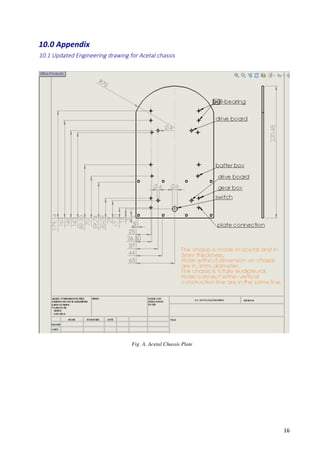
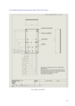
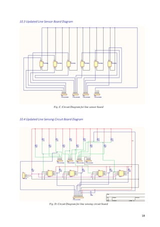

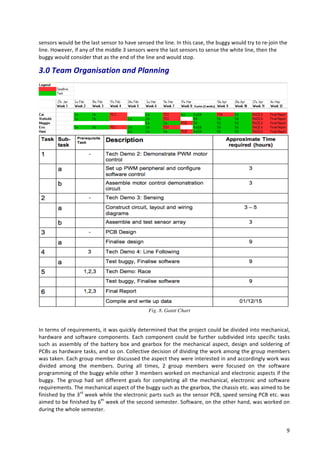
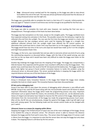
This document provides a final report on an embedded systems project to build an autonomous line-following buggy. It summarizes the key components of the buggy, including the mechanical design, electronic circuits for line and speed sensing, use of an ultrasonic sensor and RF link, and software programming. It describes the group's organization, budget, testing process, and performance at races, where the buggy placed fifth. Detailed diagrams and the pseudo code used are included in appendices.


![[IJET-V1I4P10] Authers :EiEi Thwe, Theingi](https://cdn.slidesharecdn.com/ss_thumbnails/ijet-v1i4p10-150810164804-lva1-app6892-thumbnail.jpg?width=640&height=640&fit=bounds)