Download as PDF, PPTX


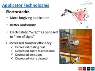


This document discusses automating the coating process and different applicator technologies. It covers spray characteristics like air atomization, hydraulic atomization, centrifugal atomization, and electrostatics. Air atomization includes conventional, HVLP, and LVMP technologies. Hydraulic atomization includes airless and air assisted airless. Centrifugal atomization uses high-speed rotation to atomize coatings. Electrostatics increases transfer efficiency by applying a charge to coatings. The document also discusses automation options like reciprocators and robotics, and factors to consider like production requirements and cycle times when selecting an automation solution.


