AUTOMATED MATERIAL HANDLING ( robots, agvs, transfer lines).pptx
1.
Presented By-
1.MADHUSUDAN SONI
2.NAVRATANRAIGAR
3.RAHUL KEER
4.RAMDHAN
Presented To-
Dr. Kailash Chaudhary
(Assistant Professor)
Department Of Mechanical Engineering
MBM University, Jodhpur
AUTOMATED MATERIAL HANDLING
2.
Presentation Outlines
Introduction ToMaterial Handling
• Why Material Handling Is Needed?
• Types Of Material Handling Systems
Automated Material Handling (AMH)
• Why we Use Automation In Material Handling
• Automated Material Handling Equipment
Transfer Lines
• Types Of Transfer Lines
• Objectives Of The Use Of Transfer Lines
Industrial Robots
Automated Guided Vehicle
3.
Introduction to MaterialHandling
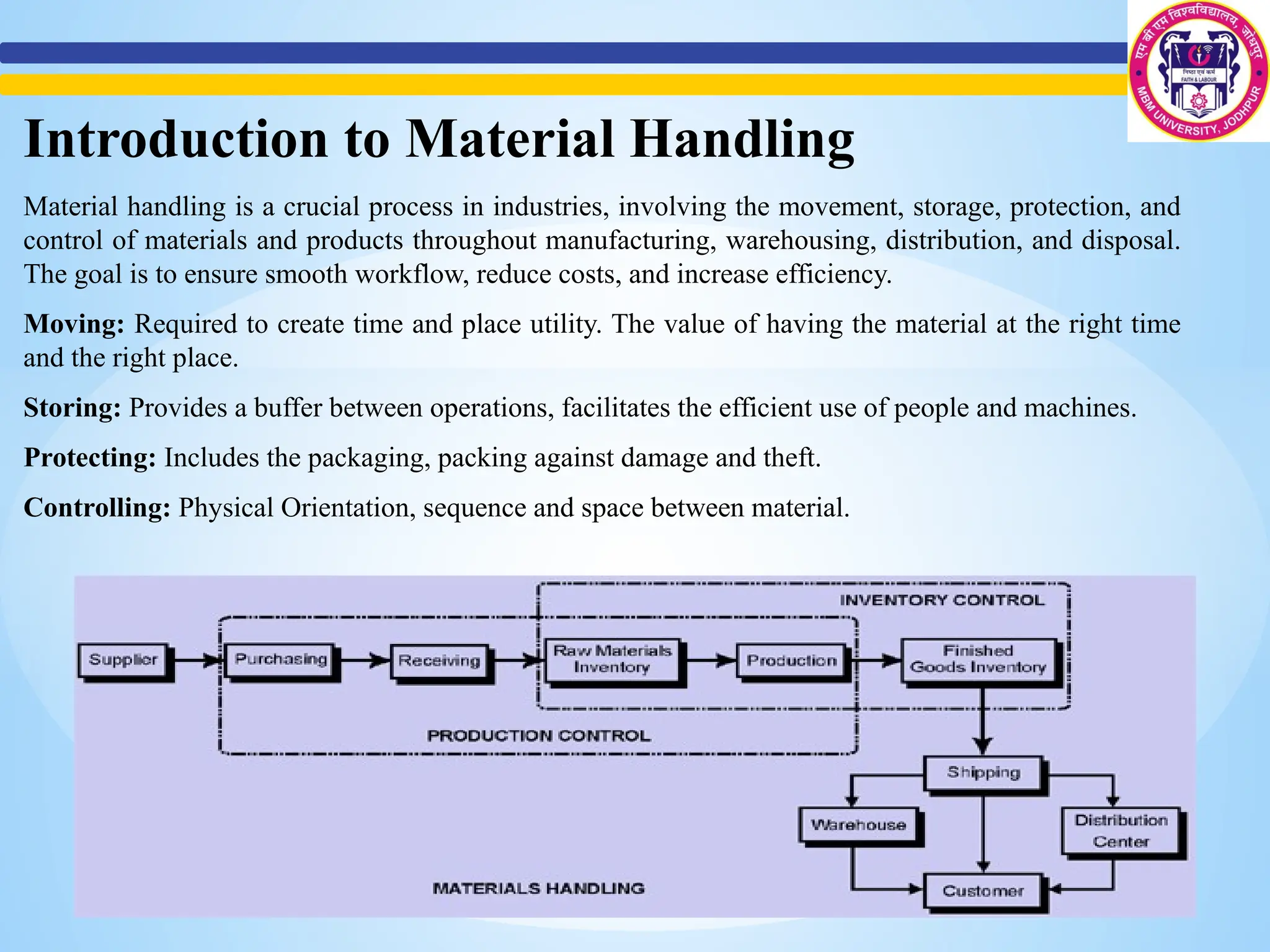
Material handling is a crucial process in industries, involving the movement, storage, protection, and
control of materials and products throughout manufacturing, warehousing, distribution, and disposal.
The goal is to ensure smooth workflow, reduce costs, and increase efficiency.
Moving: Required to create time and place utility. The value of having the material at the right time
and the right place.
Storing: Provides a buffer between operations, facilitates the efficient use of people and machines.
Protecting: Includes the packaging, packing against damage and theft.
Controlling: Physical Orientation, sequence and space between material.
4.
Types of MaterialHandling Systems
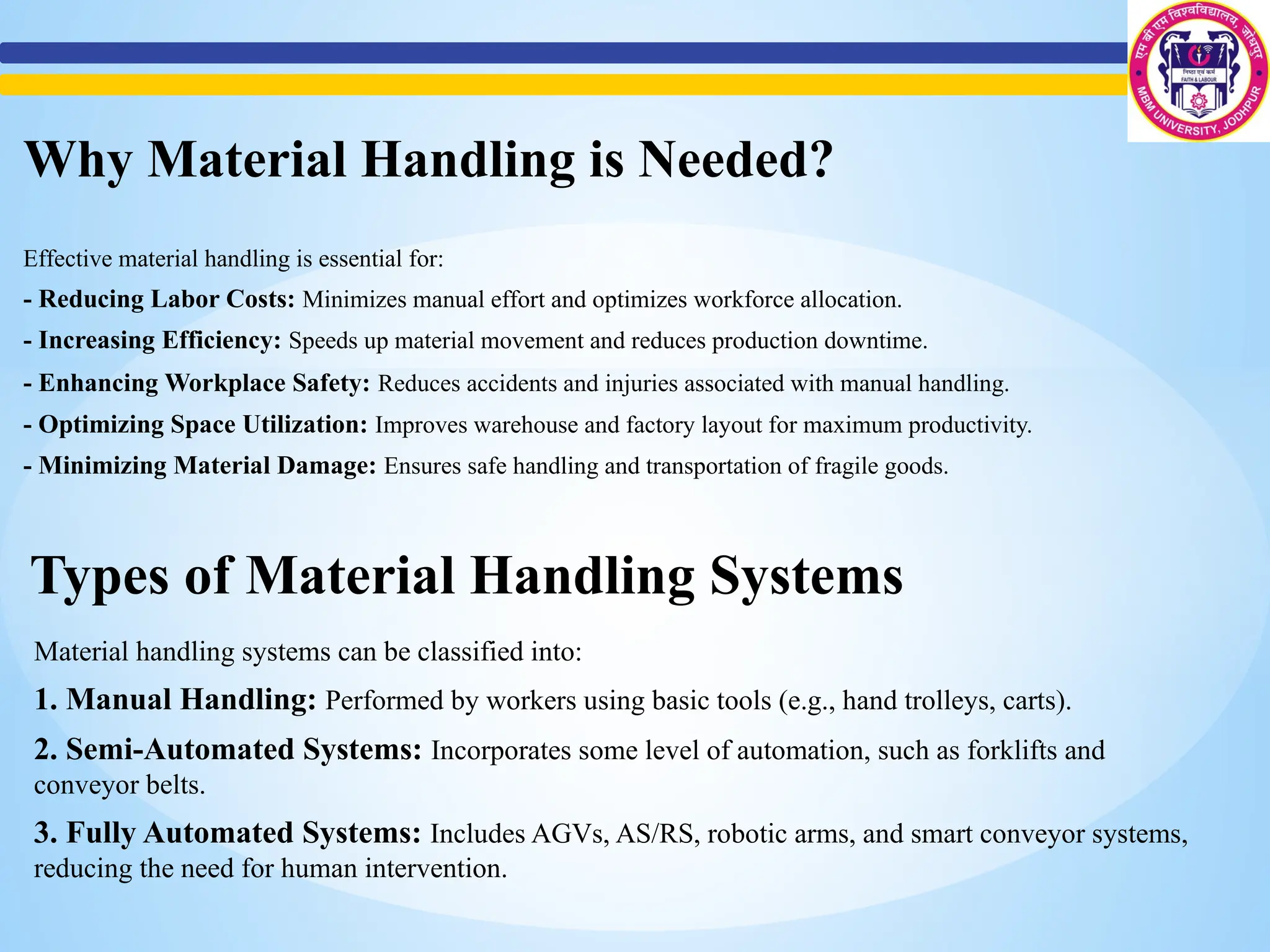
Material handling systems can be classified into:
1. Manual Handling: Performed by workers using basic tools (e.g., hand trolleys, carts).
2. Semi-Automated Systems: Incorporates some level of automation, such as forklifts and
conveyor belts.
3. Fully Automated Systems: Includes AGVs, AS/RS, robotic arms, and smart conveyor systems,
reducing the need for human intervention.
Why Material Handling is Needed?
Effective material handling is essential for:
- Reducing Labor Costs: Minimizes manual effort and optimizes workforce allocation.
- Increasing Efficiency: Speeds up material movement and reduces production downtime.
- Enhancing Workplace Safety: Reduces accidents and injuries associated with manual handling.
- Optimizing Space Utilization: Improves warehouse and factory layout for maximum productivity.
- Minimizing Material Damage: Ensures safe handling and transportation of fragile goods.
5.
WHY USE AUTOMATIONIN MATERIAL HANDLING
1. To increase labor productivity
2. To reduce labor cost
3. To mitigate the effects of labor shortages
4. To reduce or remove routine manual and clerical tasks
5. To improve worker safety
6. To improve product quality
7. To reduce manufacturing lead time
8. To accomplish what cannot be done manually
Automated Material Handling (AMH)
Automated Material Handling (AMH) uses advanced technology to streamline the transportation,
storage, and control of goods within warehouses and production facilities. AMH solutions improve
operational efficiency, accuracy, and overall productivity while reducing human errors.
AUTOMATED MATERIAL HANDLING EQUIPMENT
• Transfer Lines
• Industrial Robots
• AGVS (Automated Guided Vehicles )
6.
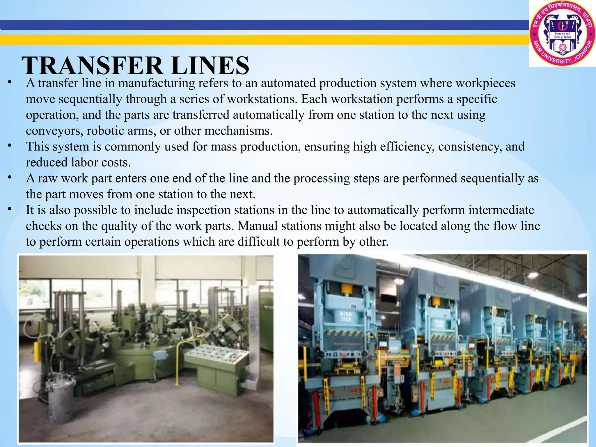
• A transferline in manufacturing refers to an automated production system where workpieces
move sequentially through a series of workstations. Each workstation performs a specific
operation, and the parts are transferred automatically from one station to the next using
conveyors, robotic arms, or other mechanisms.
• This system is commonly used for mass production, ensuring high efficiency, consistency, and
reduced labor costs.
• A raw work part enters one end of the line and the processing steps are performed sequentially as
the part moves from one station to the next.
• It is also possible to include inspection stations in the line to automatically perform intermediate
checks on the quality of the work parts. Manual stations might also be located along the flow line
to perform certain operations which are difficult to perform by other.
TRANSFER LINES
7.
Objectives of TheUse of Transfer Line
• To reduce labor costs
• To increase production rates
• To reduce work-in-process
• To minimize distances moved between operations
• To achieve specialization of operations
• To achieve integration of operations
TYPES OF TRANSFER LINES
1. In-line type
2. Segmented In-Line Type
3. Rotary type
8.
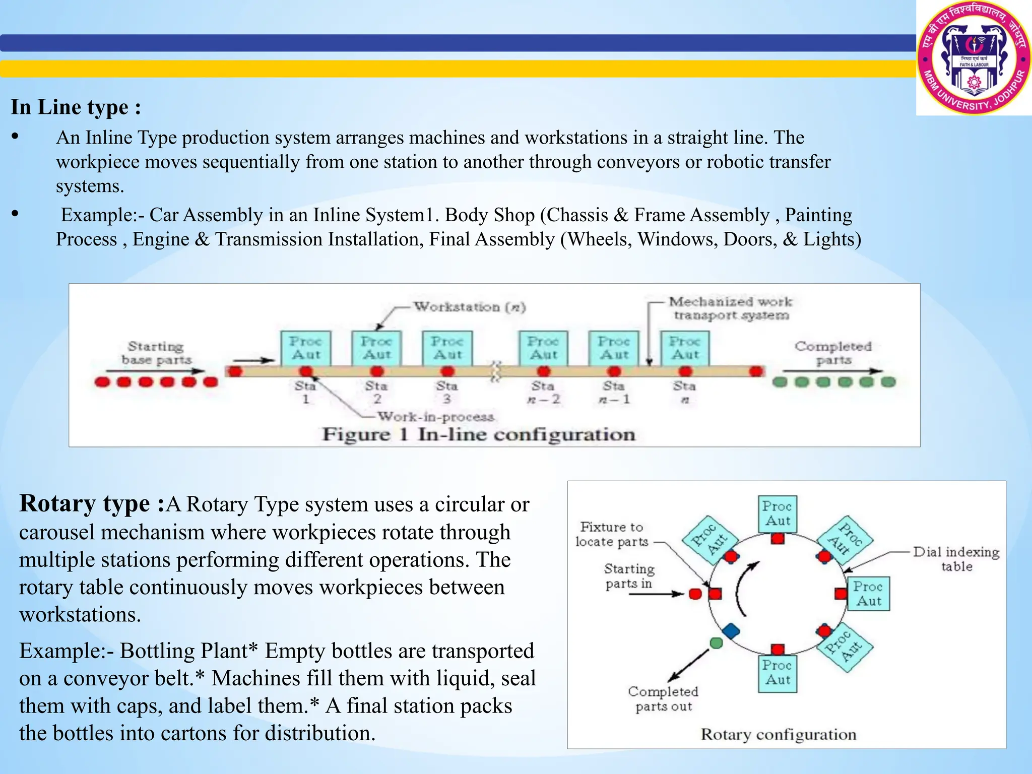
In Line type:
• An Inline Type production system arranges machines and workstations in a straight line. The
workpiece moves sequentially from one station to another through conveyors or robotic transfer
systems.
• Example:- Car Assembly in an Inline System1. Body Shop (Chassis & Frame Assembly , Painting
Process , Engine & Transmission Installation, Final Assembly (Wheels, Windows, Doors, & Lights)
Rotary type :A Rotary Type system uses a circular or
carousel mechanism where workpieces rotate through
multiple stations performing different operations. The
rotary table continuously moves workpieces between
workstations.
Example:- Bottling Plant* Empty bottles are transported
on a conveyor belt.* Machines fill them with liquid, seal
them with caps, and label them.* A final station packs
the bottles into cartons for distribution.
9.
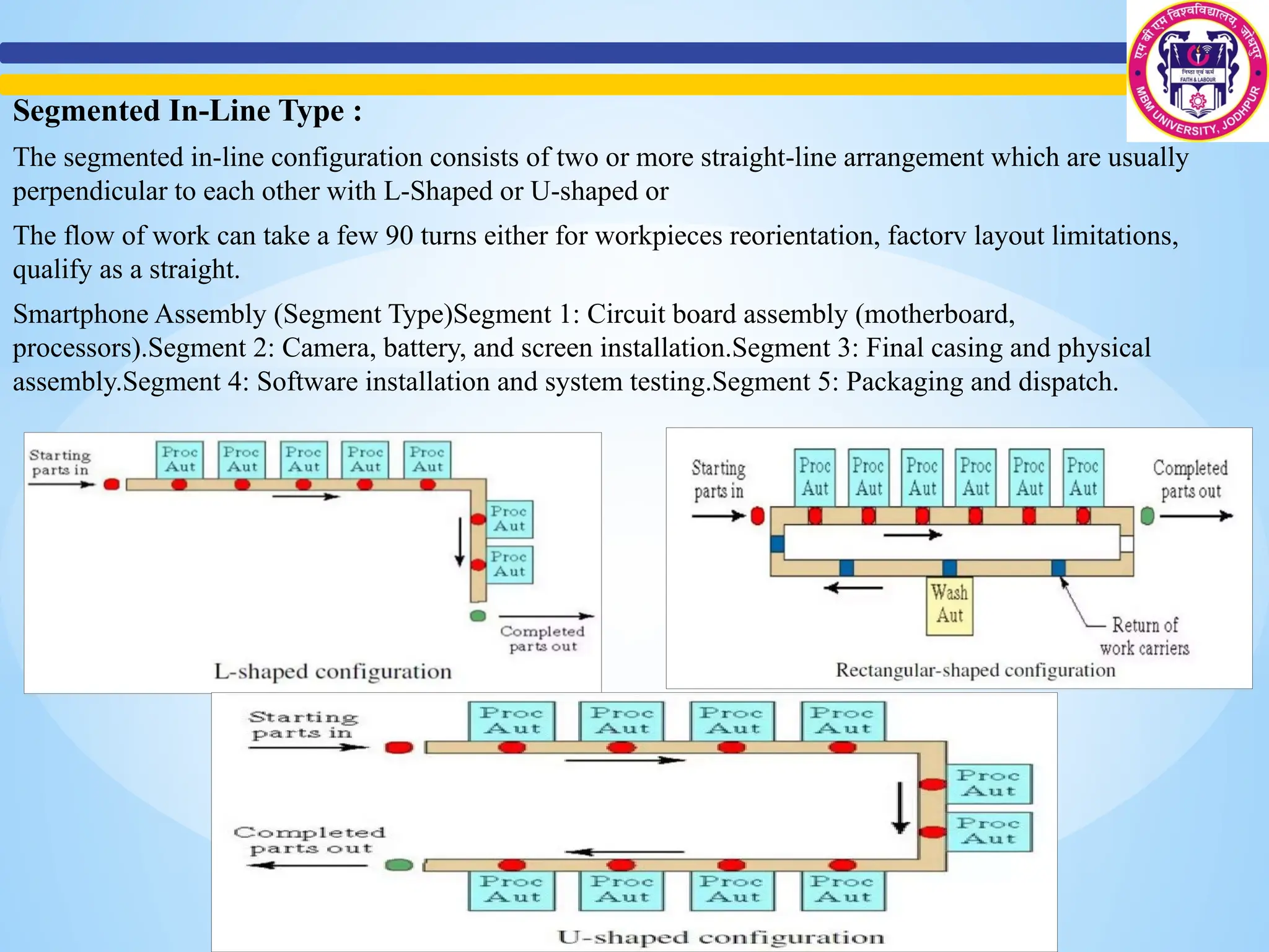
Segmented In-Line Type:
The segmented in-line configuration consists of two or more straight-line arrangement which are usually
perpendicular to each other with L-Shaped or U-shaped or
The flow of work can take a few 90 turns either for workpieces reorientation, factorv layout limitations,
qualify as a straight.
Smartphone Assembly (Segment Type)Segment 1: Circuit board assembly (motherboard,
processors).Segment 2: Camera, battery, and screen installation.Segment 3: Final casing and physical
assembly.Segment 4: Software installation and system testing.Segment 5: Packaging and dispatch.
10.
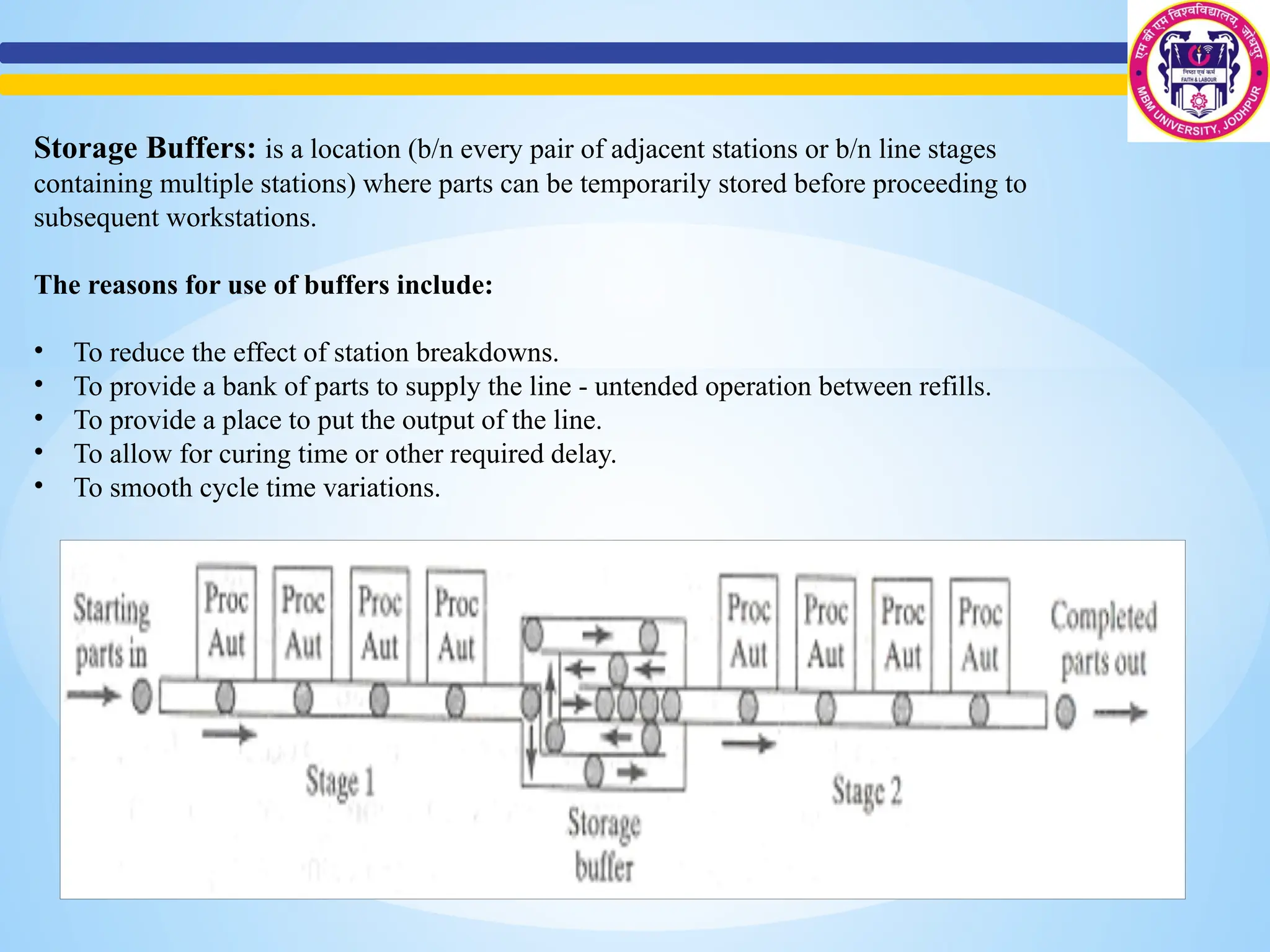
Storage Buffers: isa location (b/n every pair of adjacent stations or b/n line stages
containing multiple stations) where parts can be temporarily stored before proceeding to
subsequent workstations.
The reasons for use of buffers include:
• To reduce the effect of station breakdowns.
• To provide a bank of parts to supply the line - untended operation between refills.
• To provide a place to put the output of the line.
• To allow for curing time or other required delay.
• To smooth cycle time variations.
11.
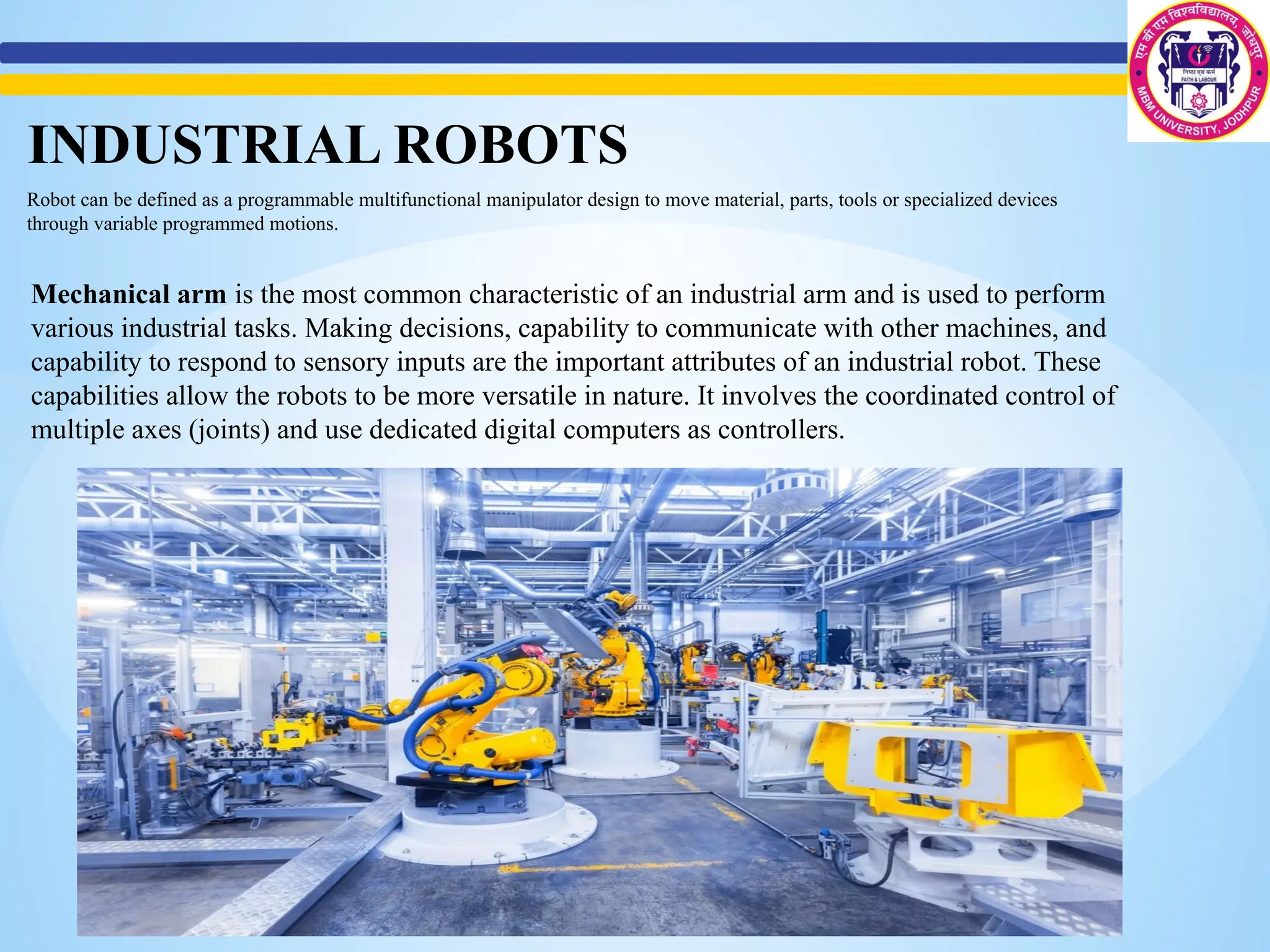
Robot can bedefined as a programmable multifunctional manipulator design to move material, parts, tools or specialized devices
through variable programmed motions.
Mechanical arm is the most common characteristic of an industrial arm and is used to perform
various industrial tasks. Making decisions, capability to communicate with other machines, and
capability to respond to sensory inputs are the important attributes of an industrial robot. These
capabilities allow the robots to be more versatile in nature. It involves the coordinated control of
multiple axes (joints) and use dedicated digital computers as controllers.
INDUSTRIAL ROBOTS
12.
The various reasonsfor the commercial and technological importance of
industrial robots include the following :
(i) Robots can be substituted for humans in hazardous or uncomfortable work environments.
A robot performs its work cycle with a consistency and repeatability that cannot be
attained by humans.
(ii) Robots can be reprogrammed. When the production run of the current task is completed,
a robot can be reprogrammed and equipped with necessary tooling to perform an
altogether different task.
(iii) Robots are controlled by computers and can therefore be connected to other computer
systems to achieve computer integrated manufacturing.
Robot Anatomy :
A robot joint is a mechanism that permits relative movement between parts of a robot arm. The
joints of a robot are designed to enable the robot to move its end-effector along a path from one
position to another as desired.
The basic movements required for the desired motion of most industrial robots are :
Rotational Movement - This enables the robot to place its arm in any direction on a horizontal
direction.
Radial Movement - This helps the robot to move its end-effector radially to reach distant points.
Vertical Movement - This enables the robot to take its end-effector to different heights.
13.
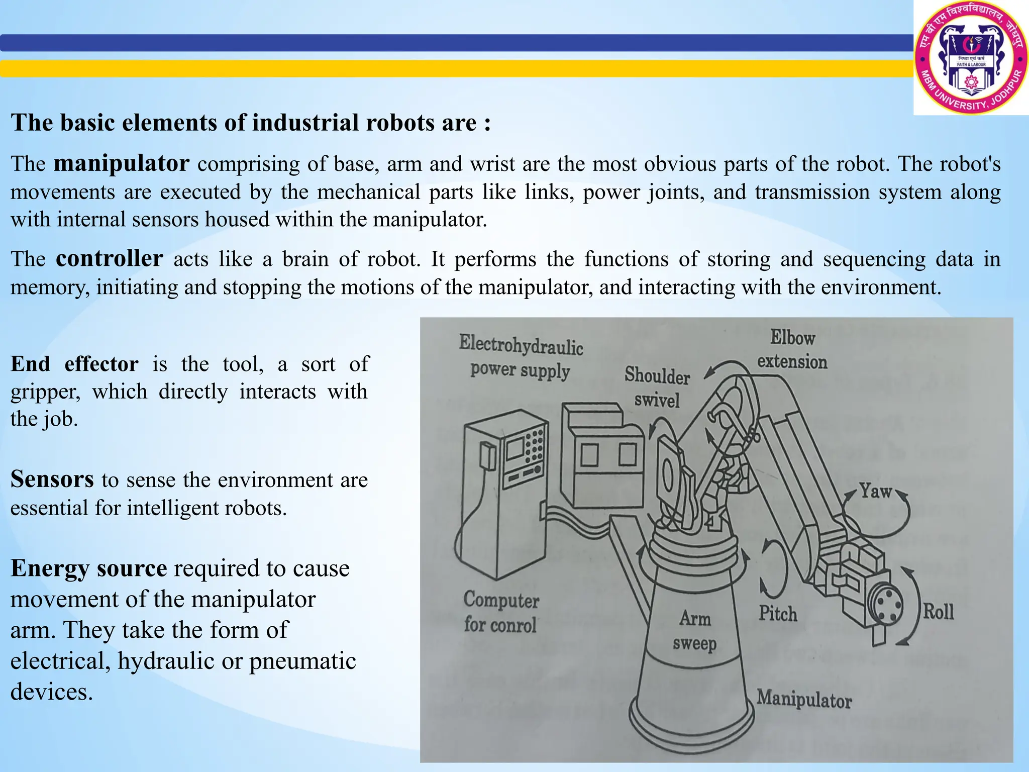
The basic elementsof industrial robots are :
The manipulator comprising of base, arm and wrist are the most obvious parts of the robot. The robot's
movements are executed by the mechanical parts like links, power joints, and transmission system along
with internal sensors housed within the manipulator.
The controller acts like a brain of robot. It performs the functions of storing and sequencing data in
memory, initiating and stopping the motions of the manipulator, and interacting with the environment.
End effector is the tool, a sort of
gripper, which directly interacts with
the job.
Sensors to sense the environment are
essential for intelligent robots.
Energy source required to cause
movement of the manipulator
arm. They take the form of
electrical, hydraulic or pneumatic
devices.
14.
Robot Classification
Robots arebeing classified on the basis of their physical configuration and control systems
adopted. These classifications are briefly described as follows :
Classification on the Basis of Physical Configurations
On the basis of physical configuration industrial robots are classified in four different types. They
are :
i. Cartesian Configuration : Robots having cartesian configurations consist of links connected by
linear joints (L). As the configuration has three perpendicular slides, they are also called rectilinear
robots. Robot having a similar configuration is known as Gantry Robots. Its structure resembles a
gantry-type crane.
ii. Cylindrical Configuration : In the cylindrical configuration, robots have one rotatory (R) joint at
the base and linear (L) joints succeed to connect the links. The space in which this robot operates is
cylindrical in shape, hence the name cylindrical configuration.
iii. Polar Configuration : Polar robots have a work space of spherical shape. In general, the arm is
linked to the base with a twisting (T) joint and rotatory (R) and or linear (L) joints. The designation
of the arm for this arm can be TRL or TRR. Robots with the description of TRL are also called
spherical robots. Those having the designation of TRR are called as articulated robots. It resembles
a human arm in terms of configuration.
iv. Jointed-Arm Configuration : The combination of cylindrical and articulated configurations is
known as jointed-arm configuration. The arm of the robot is connected to the base with a twisting
joint. Rotatory joints are used to connect the links in the arm. Generally, the rotation takes place in
the vertical plane. Popular robot falling under this category is called SCARA (Selective
Compliance Assembly Robot Arm). It is basically used for the assembly purpose.
15.
Classification based onControl Systems
On the basis of the control systems adopted, robots are classified into the following categories :
(i) Point-to-point (PTP) control robot : The PTP robot is capable of moving from one point to the other
point. The locations are recorded in the control memory. The paths are not controlled by the path
guide. Instead, the desired path is traced by programming a series of points. Component insertion,
spot welding, hole drilling, machine loading, unloading and crude assembly are some of the common
applications of this type of robot.
(ii) Continuous-path (CP) control robot : The movement along the controlled path is performed by the
CP robot. Along the controlled path, with CP control, the robot can stop any specified point. In the
robot’s control memory, all the points must be stored explicitly. Straight-line motion is being carried
out by these types of robots. Some continuous-path controlled robots also have the capability to
follow a smooth curve path that has been defined by the programmer. Here, the programmer manually
moves the robot arm through the desired path and the controller unit stores a large number of
individual point locations along the path in memory.
(iii) Controlled-path robot : In controlled-path robots, the control equipment can develop paths of
different geometry such as straight lines, circles, and interpolated curves with a high degree of
accuracy. Good accuracy can be obtained at any point along the specified path. Only the start and
finish points and the path definition function must be stored in the robot’s control memory. It is
important to mention that all controlled-path robots have a servo capability to correct their path.
16.
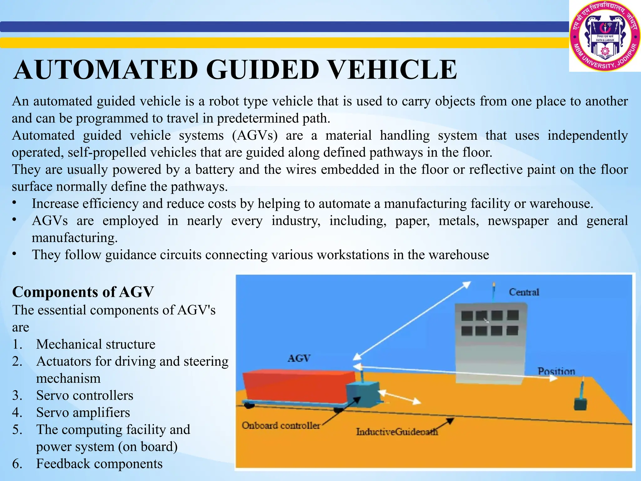
An automated guidedvehicle is a robot type vehicle that is used to carry objects from one place to another
and can be programmed to travel in predetermined path.
Automated guided vehicle systems (AGVs) are a material handling system that uses independently
operated, self-propelled vehicles that are guided along defined pathways in the floor.
They are usually powered by a battery and the wires embedded in the floor or reflective paint on the floor
surface normally define the pathways.
• Increase efficiency and reduce costs by helping to automate a manufacturing facility or warehouse.
• AGVs are employed in nearly every industry, including, paper, metals, newspaper and general
manufacturing.
• They follow guidance circuits connecting various workstations in the warehouse
AUTOMATED GUIDED VEHICLE
Components of AGV
The essential components of AGV's
are
1. Mechanical structure
2. Actuators for driving and steering
mechanism
3. Servo controllers
4. Servo amplifiers
5. The computing facility and
power system (on board)
6. Feedback components
17.
Functions of AGV
1.Guidance
Allows the vehicle to follow a predetermined route, which is optimized for the material flow
pattern of a given application.
2. Routing
Ability to make decisions along the guidance path in order to select optimum routes to specific
applications.
3. Traffic Handling
It is the ability of the vehicle to avoid collisions with other vehicles at the same time maximizing
vehicle flow and therefore the load management throughout the system.
4. Load Handling and Transfer
Pickup and delivery method for AGVs, which may be simple and integrated with other subsystems.
5. System Management
Should be able to control the system for efficient system operation.
18.
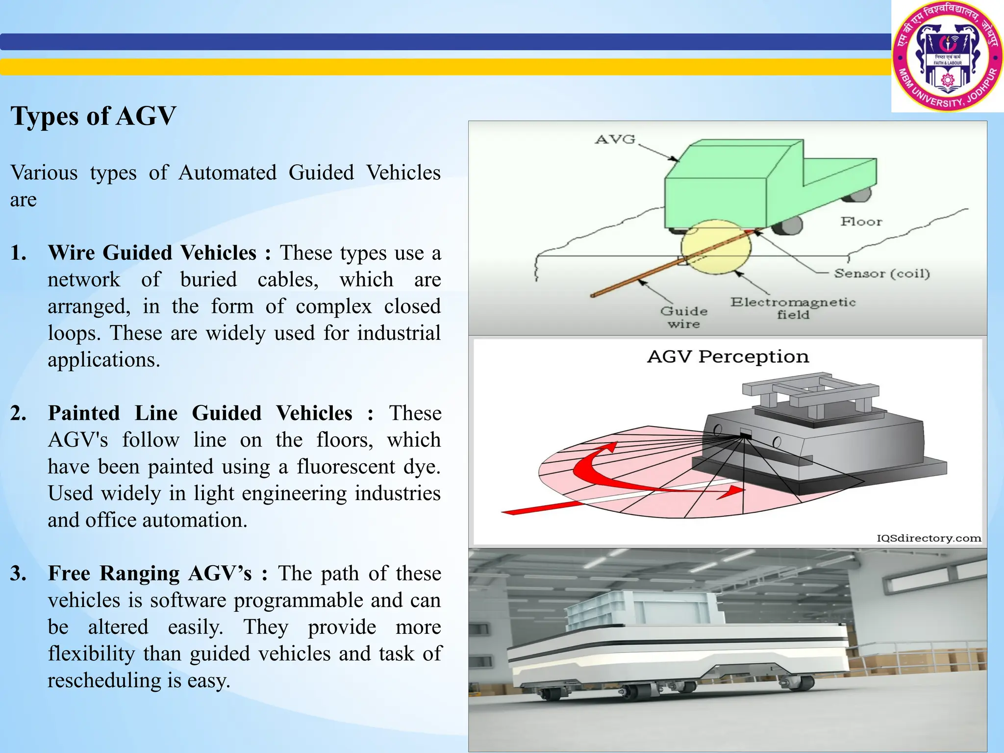
Types of AGV
Varioustypes of Automated Guided Vehicles
are
1. Wire Guided Vehicles : These types use a
network of buried cables, which are
arranged, in the form of complex closed
loops. These are widely used for industrial
applications.
2. Painted Line Guided Vehicles : These
AGV's follow line on the floors, which
have been painted using a fluorescent dye.
Used widely in light engineering industries
and office automation.
3. Free Ranging AGV’s : The path of these
vehicles is software programmable and can
be altered easily. They provide more
flexibility than guided vehicles and task of
rescheduling is easy.
19.
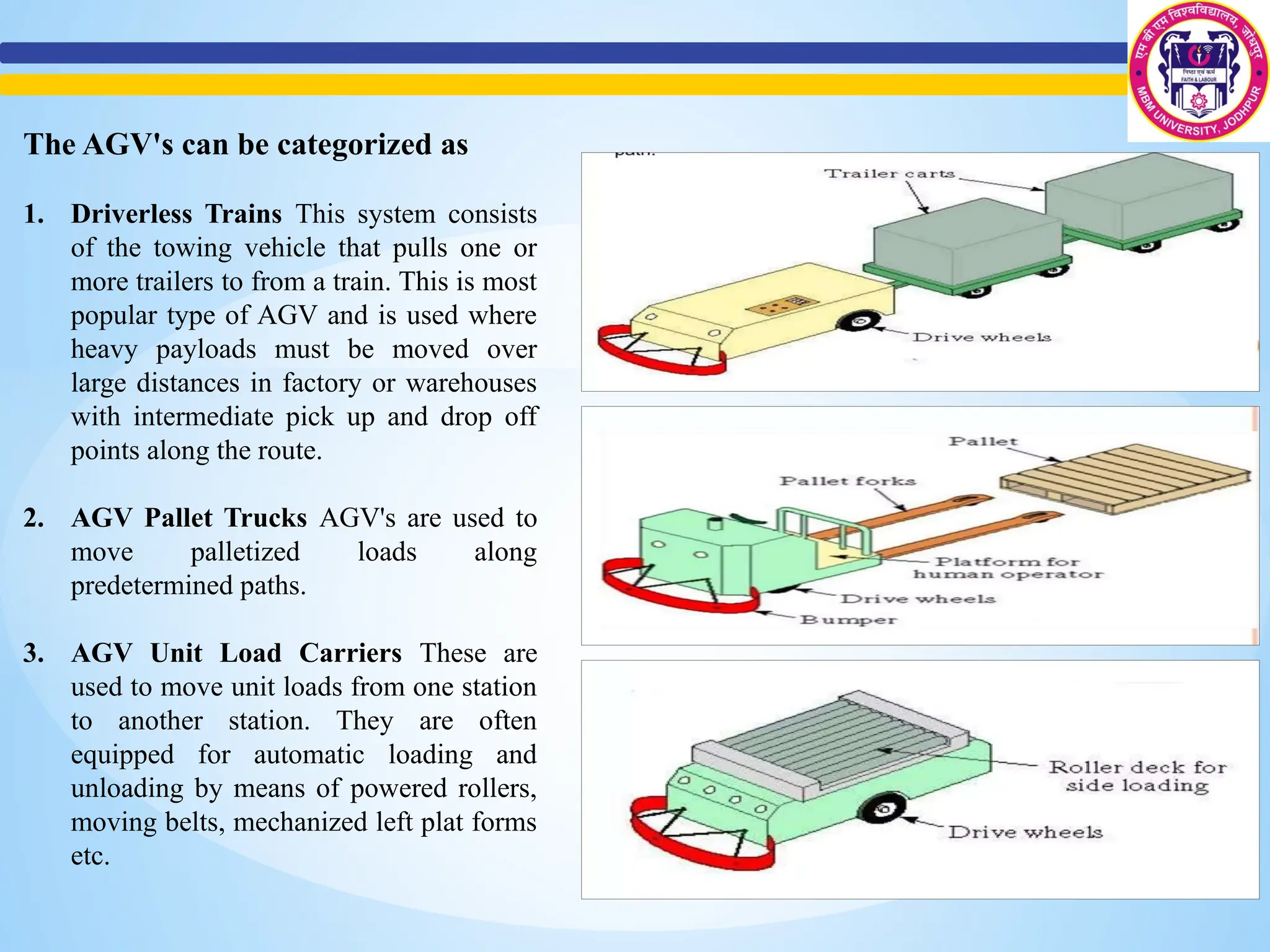
The AGV's canbe categorized as
1. Driverless Trains This system consists
of the towing vehicle that pulls one or
more trailers to from a train. This is most
popular type of AGV and is used where
heavy payloads must be moved over
large distances in factory or warehouses
with intermediate pick up and drop off
points along the route.
2. AGV Pallet Trucks AGV's are used to
move palletized loads along
predetermined paths.
3. AGV Unit Load Carriers These are
used to move unit loads from one station
to another station. They are often
equipped for automatic loading and
unloading by means of powered rollers,
moving belts, mechanized left plat forms
etc.
21.
Application of AGV
1.Driverless Train Operation Movement of large quantities of materials over relatively large
distances.
2. Distribution Systems - Unit load carriers and unit trucks are used for storage and distribution
systems. Here the working of AGV's interface with other systems like automated storage and
retrieval systems.
3. Assembly Line Operations
4. Application in flexible manufacturing systems.
5. Other general application in office, hospitals etc.
22.
References
[1] Industrial Engineeringand Production Management by M Telsang, S Chand Publications
[2] Koren, Y. (2010). The Global Manufacturing Revolution: Product-Process-Business
Integration and Reconfigurable Systems. Wiley.
[3] ] Craig, J. J. (2021). Introduction to Robotics: Mechanics and Control (4th Edition).
Pearson.
[4] Berman, S., & Edan, Y. (2002). "Decentralized Autonomous AGV System for Material
Handling," International Journal of Production Research, 40(15), 3995-4006.
[5] Material Handling 24/7🔗 https://www.materialhandling247.com/
[6]International Journal of Advanced Manufacturing Technology🔗
https://www.springer.com/journal/170
[7] Groover, M. P. (2016). Automation, Production Systems, and Computer-Integrated
Manufacturing (4th Edition). Pearson.
[8] Hopp, W. J., & Spearman, M. L. (2011). Factory Physics (3rd Edition). Waveland Press.
![References
[1] Industrial Engineering and Production Management by M Telsang, S Chand Publications
[2] Koren, Y. (2010). The Global Manufacturing Revolution: Product-Process-Business
Integration and Reconfigurable Systems. Wiley.
[3] ] Craig, J. J. (2021). Introduction to Robotics: Mechanics and Control (4th Edition).
Pearson.
[4] Berman, S., & Edan, Y. (2002). "Decentralized Autonomous AGV System for Material
Handling," International Journal of Production Research, 40(15), 3995-4006.
[5] Material Handling 24/7🔗 https://www.materialhandling247.com/
[6]International Journal of Advanced Manufacturing Technology🔗
https://www.springer.com/journal/170
[7] Groover, M. P. (2016). Automation, Production Systems, and Computer-Integrated
Manufacturing (4th Edition). Pearson.
[8] Hopp, W. J., & Spearman, M. L. (2011). Factory Physics (3rd Edition). Waveland Press.](https://image.slidesharecdn.com/automatedmaterialhandling-250416042154-456387d6/75/AUTOMATED-MATERIAL-HANDLING-robots-agvs-transfer-lines-pptx-22-2048.jpg)