Downloaded 1,849 times


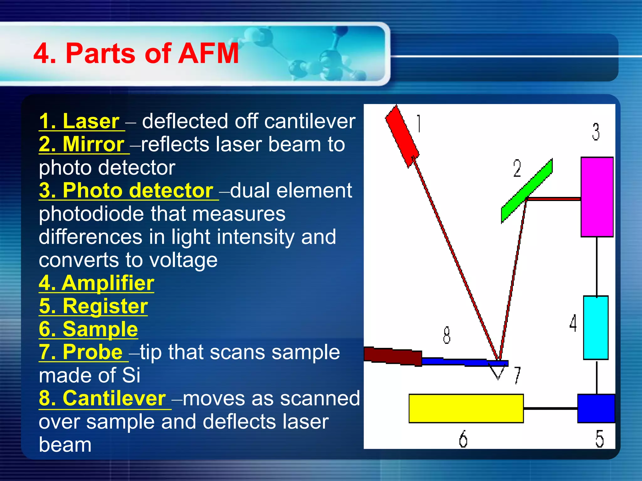


Atomic force microscopy (AFM) is a technique used to image surfaces at the nanoscale. The document outlines the history, components, operating modes, applications, and limitations of AFM. It discusses how AFM works by scanning a sample with a sharp tip attached to a flexible cantilever, measuring deflections to construct 3D surface images. Three common modes are contact, non-contact, and tapping mode. AFM can image a variety of materials and is useful for measuring surface roughness, adhesion, and other nanoscale properties. While resolution is limited by tip size, continued improvements aim to develop sharper tips and less damaging probes.