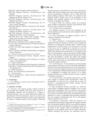
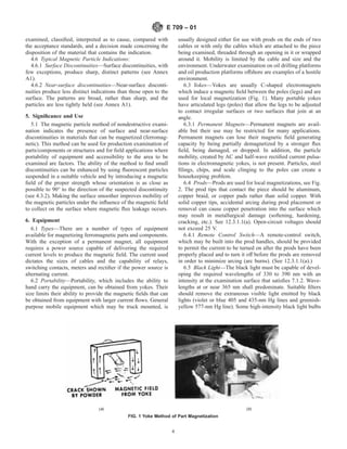
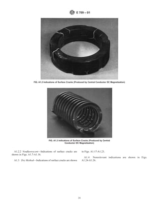
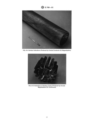
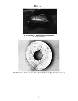
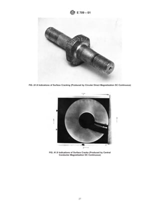
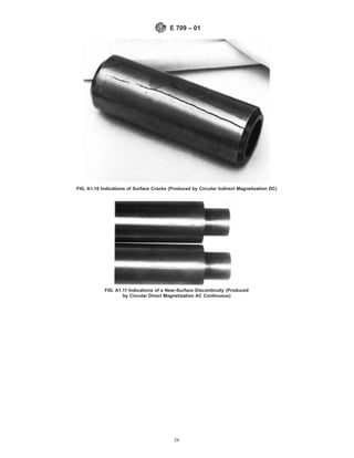
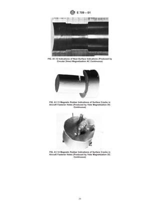
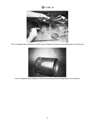
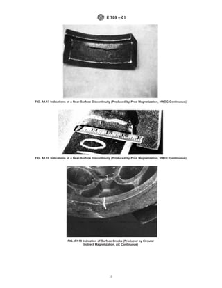
1) This document provides guidelines for magnetic particle examination, a nondestructive testing method for detecting cracks and other discontinuities near the surface of ferromagnetic materials.
2) The magnetic particle method works by magnetizing the material, applying magnetic particles, and observing where particles accumulate at points of magnetic flux leakage caused by discontinuities.
3) The guidelines describe procedures for part preparation, different magnetization techniques, types of magnetic particles, interpretation of indications, and other aspects of the examination process.
2. Significance and Use 5
Equipment 6
Types 6.1
SECTION
Portability 6.2
Yokes 6.3
Prods 6.4
Black Light 6.5
Equipment Verification 6.6
Examination Area 7
Light Intensity for Examination 7.1
Housekeeping 7.2
Magnetic Particle Materials 8
Particle Types 8.2
Particle Characteristics 8.3
Dry Particles 8.4
Wet Particle Systems 8.5
Part Preparation 9
General 9.1
Cleaning Examination Surface 9.2
Sequence of Operations 10
Sequencing Particle Application and Establishing Mag-
netic Flux Field
10.1
Types of Magnetizing Currents 11
Basic Current Types 11.1
Part Magnetization Techniques 12
Examination Coverage 12.1
Direct and Indirect Magnetization 12.2
Choosing a Magnetization Technique 12.3
Direction of Magnetic Fields 13
Discontinuity Orientation vs Magnetic Field Direction 13.1
Circular Magnetization 13.2
Torodial Magnetization 13.3
Longitudinal Magnetization 13.4
Multidirectional Magnetization 13.5
Magnetic Field Strength 14
Magnetizing Field Strengths 14.1
Establishing Field Strengths 14.2
Guidelines for Establishing Magnetic Fields 14.3
Application of Dry and Wet Magnetic Particles 15
Dry Magnetic Particles 15.1
Wet Particles Applications 15.2
Magnetic Slurry/Paint 15.3
Magnetic Polymers 15.4
Interpretation of Indications 16
Valid Indications 16.1
Recording of Indications 17
Means of Recording 17.1
Accompanying Information 17.2
Demagnetization 18
Applicability 18.1
Demagnetization Methods 18.2
Extent of Demagnetization 18.3
Post Examination Cleaning 19
Particle Removal 19.1
Means of Particle Removal 19.2
Evaluation of System Performance/Sensitivity 20
Contributor Factors 20.1
Maintenance and Calibration of Equipment 20.2
Equipment Checks 20.3
Examination Area Light Level Control 20.4
Dry Particle Quality Control Tests 20.5
Wet Particle Quality Control Tests 20.6
Bath Characteristics Control 20.7
Verifying System Performance 20.8
Procedure and Report 21
Written Procedure 21.1
Written Reports 21.2
Acceptance Standards 22
Safety 23
SECTION
Precision and Bias 24
Keywords 25
Annex Annex A1
Appendix X1. Appendix
X1
Appendix X2. Appendix
X2
1.8 The numerical values shown in inch-pound units are to
be regarded as the standard. SI units are provided for informa-
tion only.
1.9 This standard does not purport to address all of the
safety concerns, if any, associated with its use. It is the
responsibility of the user of this standard to establish appro-
priate safety and health practices and determine the applica-
bility of regulatory limitations prior to use.
2. Referenced Documents
2.1 ASTM Standards:
A 275/A 275M Test Method for Magnetic Particle Exami-
nation of Steel Forgings3
A 456/A 456M Specification for Magnetic Particle Exami-
nation of Large Crankshaft3
D 93 Test Methods for Flash Point by Pensky-Martens
Closed Tester4
D 129 Test Method for Sulfur in Petroleum Products (Gen-
eral Bomb Method)4
D 445 Test Method for Kinematic Viscosity of Transparent
and Opaque Liquids (and the Calculation of Dynamic
Viscosity)4
D 808 Test Method for Chlorine in New and Used Petro-
leum Products (Bomb Method)4
D 1966 Test Method for Foots in Raw Linseed Oil Gravi-
metric Method5
E 165 Test Method for Liquid Penetrant Examination6
E 543 Practice for Agencies Performing Nondestructive
Testing6
E 1316 Terminology for Nondestructive Examinations6
E 1444 Practice for Magnetic Particle Examination6
2.2 Society of Automotive Engineers (SAE): Aerospace
Materials Specifications:7
AMS 2300 Premium Aircraft Quality Steel Cleanliness
Magnetic Particle Inspection Procedure
AMS 2301 Aircraft Quality Steel Cleanliness Magnetic Par-
ticle Inspection Procedure
AMS 2303 Aircraft Quality Steel Cleanliness Martensitic
Corrosion Resistant Steels Magnetic Particle Inspection
Procedure
3
Annual Book of ASTM Standards, Vol 01.05.
4
Annual Book of ASTM Standards, Vol 05.01.
5
Annual Book of ASTM Standards, Vol 06.03.
6
Annual Book of ASTM Standards, Vol 03.03.
7
Available from Society of Automotive Engineers, 400 Commonwealth Drive,
Warrendale, PA 15096.
E 709 – 01
2
3. AMS 2641 Vehicle Magnetic Particle Inspection
AMS 3040 Magnetic Particles, Non-fluorescent, Dry
Method
AMS 3041 Magnetic Particles, Non-fluorescent, Wet
Method, Oil Vehicle, Ready to Use
AMS 3042 Magnetic Particles, Non-fluorescent, Wet
Method, Dry Powder
AMS 3043 Magnetic Particles, Non-fluorescent, Oil Ve-
hicle, Aerosol Packaged
AMS 3044 Magnetic Particles, Fluorescent, Wet Method,
Dry Powder
AMS 3045 Magnetic Particles, Non-fluorescent, Wet
Method, Oil Vehicle, Ready to Use
AMS 3046 Magnetic Particles, Non-fluorescent, Wet
Method, Oil Vehicle, Aerosol Packaged
AMS 5062 Steel, Low Carbon Bars, Forgings, Tubing,
Sheet, Strip, and Plate 0.25 Carbon, Maximum
AMS 5355 Investment Castings
AMS-I-83387 Inspection Process, Magnetic Rubber
AS 4792 Water Conditioning Agents for Aqueous Magnetic
Particle Inspection
AS 5282 Tool Steel Ring Standard for Magnetic Particle
Inspection
AS 5371 Reference Standards Notched Shims for Magnetic
Particle Inspection
2.3 American Society for Nondestructive Testing:8
SNT-TC-1A Recommended Practice Magnetic Particle
Method
CP-189 ASNT Qualification and Certification of Nonde-
structive Testing Personnel
2.4 Federal Standards:9
A-A-59230 Fluid, Magnetic Particle Inspection, Suspension
FED-STD 313 Material Safety Data Sheets Preparation and
the Submission of
2.5 OSHA Document:10
29CFR 1910.1200 Hazard Communication
2.6 AIA Documents:
NAS 410 Nondestructive Testing Personnel Qualification
and Certification
3. Terminology
3.1 For definitions of terms used in the practice, refer to
Terminology E 1316
4. Summary of Guide
4.1 Principle—The magnetic particle method is based on
the principle that magnetic field lines when present in a
ferromagnetic material, will be distorted by a change in
material continuity, such as a sharp dimensional change or a
discontinuity. If the discontinuity is open to or close to the
surface of a magnetized material, flux lines will be distorted at
the surface, a condition termed as “flux leakage.” When fine
magnetic particles are distributed over the area of the discon-
tinuity while the flux leakage exists, they will be held in place
and the accumulation of particles will be visible under the
proper lighting conditions. While there are variations in the
magnetic particle method, they all are dependent on this
principle, that magnetic particles will be retained at the
locations of magnetic flux leakage.
4.2 Method—While this practice permits and describes
many variables in equipment, materials, and procedures, there
are three steps essential to the method:
4.2.1 The part must be magnetized.
4.2.2 Magnetic particles of the type designated in the
contract/purchase order/specification must be applied while the
part is magnetized.
4.2.3 Any accumulation of magnetic particles must be
observed, interpreted, and evaluated.
4.3 Magnetization:
4.3.1 Ways to Magnetize—A ferromagnetic material can be
magnetized either by passing an electric current through the
material or by placing the material within a magnetic field
originated by an external source. The entire mass or a portion
of the mass can be magnetized as dictated by size and
equipment capacity or need. As previously noted, the discon-
tinuity must interrupt the normal path of the magnetic field
lines. If a discontinuity is open to the surface, the flux leakage
will be at the maximum for that particular discontinuity. When
that same discontinuity is below the surface, flux leakage
evident on the surface will be less. Practically, discontinuities
must be open to the surface, to create sufficient flux leakage to
accumulate magnetic particles.
4.3.2 Field Direction—If a discontinuity is oriented parallel
to the magnetic field lines, it may be essentially undetectable.
Therefore, since discontinuities may occur in any orientation, it
may be necessary to magnetize the part or area of interest twice
or more sequentially in different directions by the same method
or a combination of methods (see Section 13) to induce
magnetic field lines in a suitable direction in order to perform
an adequate examination.
4.3.3 Field Strength—The magnetic field must be of suffi-
cient strength to indicate those discontinuities which are
unacceptable, yet must not be so strong that an excess of
particles is accumulated locally thereby masking relevant
indications (see Section 14).
4.4 Types of Magnetic Particles and Their Use—There are
various types of magnetic particles available for use in mag-
netic particle examination. They are available as dry powders
(fluorescent and nonfluorescent) ready for use as supplied (see
8.4), powder concentrates (fluorescent and nonfluorescent) for
dispersion in water or suspending light petroleum distillates
(see 8.5), magnetic slurries/paints (see 8.5.7), and magnetic
polymer dispersions (see 8.5.8).
4.5 Evaluation of Indications—When the material to be
examined has been properly magnetized, the magnetic particles
have been properly applied, and the excess particles properly
removed, there will be accumulations of magnetic particles at
the points of flux leakage. These accumulations show the
distortion of the magnetic field and are called indications.
Without disturbing the particles, the indications must be
8
Available from American Society for Nondestructive Testing, 1711 Arlingate
Plaza, P.O. Box 28518, Columbus, OH 43228-0518.
9
Available from Standardization Documents Order Desk, Bldg. 4 Section D, 700
Robbins Ave., Philadelphia, PA 19111-5094, Attn: NPODS.
10
Available from Occupational Safety and Health Review Commission, 1825 K
Street, N.W., Washington, DC 20006.
E 709 – 01
3
4. examined, classified, interpreted as to cause, compared with
the acceptance standards, and a decision made concerning the
disposition of the material that contains the indication.
4.6 Typical Magnetic Particle Indications:
4.6.1 Surface Discontinuities—Surface discontinuities, with
few exceptions, produce sharp, distinct patterns (see Annex
A1).
4.6.2 Near-surface discontinuities—Near-surface disconti-
nuities produce less distinct indications than those open to the
surface. The patterns are broad, rather than sharp, and the
particles are less tightly held (see Annex A1).
5. Significance and Use
5.1 The magnetic particle method of nondestructive exami-
nation indicates the presence of surface and near-surface
discontinuities in materials that can be magnetized (ferromag-
netic). This method can be used for production examination of
parts/components or structures and for field applications where
portability of equipment and accessibility to the area to be
examined are factors. The ability of the method to find small
discontinuities can be enhanced by using fluorescent particles
suspended in a suitable vehicle and by introducing a magnetic
field of the proper strength whose orientation is as close as
possible to 90° to the direction of the suspected discontinuity
(see 4.3.2). Making the surface smoother improves mobility of
the magnetic particles under the influence of the magnetic field
to collect on the surface where magnetic flux leakage occurs.
6. Equipment
6.1 Types—There are a number of types of equipment
available for magnetizing ferromagnetic parts and components.
With the exception of a permanent magnet, all equipment
requires a power source capable of delivering the required
current levels to produce the magnetic field. The current used
dictates the sizes of cables and the capability of relays,
switching contacts, meters and rectifier if the power source is
alternating current.
6.2 Portability—Portability, which includes the ability to
hand carry the equipment, can be obtained from yokes. Their
size limits their ability to provide the magnetic fields that can
be obtained from equipment with larger current flows. General
purpose mobile equipment which may be truck mounted, is
usually designed either for use with prods on the ends of two
cables or with only the cables which are attached to the piece
being examined, threaded through an opening in it or wrapped
around it. Mobility is limited by the cable and size and the
environment. Underwater examination on oil drilling platforms
and oil production platforms offshore are examples of a hostile
environment.
6.3 Yokes—Yokes are usually C-shaped electromagnets
which induce a magnetic field between the poles (legs) and are
used for local magnetization (Fig. 1). Many portable yokes
have articulated legs (poles) that allow the legs to be adjusted
to contact irregular surfaces or two surfaces that join at an
angle.
6.3.1 Permanent Magnets—Permanent magnets are avail-
able but their use may be restricted for many applications.
Permanent magnets can lose their magnetic field generating
capacity by being partially demagnetized by a stronger flux
field, being damaged, or dropped. In addition, the particle
mobility, created by AC and half-wave rectified current pulsa-
tions in electromagnetic yokes, is not present. Particles, steel
filings, chips, and scale clinging to the poles can create a
housekeeping problem.
6.4 Prods—Prods are used for local magnetizations, see Fig.
2. The prod tips that contact the piece should be aluminum,
copper braid, or copper pads rather than solid copper. With
solid copper tips, accidental arcing during prod placement or
removal can cause copper penetration into the surface which
may result in metallurgical damage (softening, hardening,
cracking, etc.). See 12.3.1.1(a). Open-circuit voltages should
not exceed 25 V.
6.4.1 Remote Control Switch—A remote-control switch,
which may be built into the prod handles, should be provided
to permit the current to be turned on after the prods have been
properly placed and to turn it off before the prods are removed
in order to minimize arcing (arc burns). (See 12.3.1.1(a).)
6.5 Black Light—The black light must be capable of devel-
oping the required wavelengths of 330 to 390 nm with an
intensity at the examination surface that satisfies 7.1.2. Wave-
lengths at or near 365 nm shall predominate. Suitable filters
should remove the extraneous visible light emitted by black
lights (violet or blue 405 and 435-nm Hg lines and greenish-
yellow 577-nm Hg line). Some high-intensity black light bulbs
(a) (b)
FIG. 1 Yoke Method of Part Magnetization
E 709 – 01
4
5. may emit unacceptable amounts of greenish-yellow light which
may cause fluorescent indications to become invisible. A drop,
greater than 10 %, in line voltage greater than 610 % can
cause a change in black light output with consequent incon-
sistent performance. A constant voltage transformer should be
used where there is evidence of voltage changes greater than
10 %.
6.6 Equipment Verification—See Section 20.
7. Examination Area
7.1 Light Intensity for Examination—Magnetic indications
found using nonfluorescent particles are examined under vis-
ible light. Indications found using fluorescent particles must be
examined under black (ultraviolet) light. This requires a
darkened area with accompanying control of the visible light
intensity.
7.1.1 Visible Light Intensity—The intensity of the visible
light at the surface of the part/work piece undergoing exami-
nation should be a minimum of 100 foot candles (1000 lux).
The intensity of ambient visible light in the darkened area
where fluorescent magnetic particles examination is performed
should not exceed 2 foot candles (20 lux).
7.1.1.1 Field Inspections—For some field inspections using
nonfluorescent particles, visible light intensities as low as 50
foot candles (500 lux) may be used when agreed on by the
contracting agency.
7.1.2 Black (Ultraviolet) Light:
7.1.2.1 Black Light Intensity—The black light intensity at
the examination surface shall be not less than 1000 µW/cm2
when measured with a suitable black light meter.
7.1.2.2 Black Light Warm-up—Allow the black light to
warm up for a minimum of 5 min prior to its use or
measurement of the intensity of the ultraviolet light emitted.
7.1.3 Dark Area Eye Adaptation—The generally accepted
practice is that an inspector be in the darkened area at least one
(1) minute so that his/her eyes will adapt to dark viewing prior
to examining parts under UV illumination.11
Caution—
Photochromic or permanently tinted lenses should not be worn
during examination.
7.2 Housekeeping—The examination area should be kept
free of interfering debris. If fluorescent materials are involved,
the area should also be kept free of fluorescent objects not
related to the part/piece being examined.
8. Magnetic Particle Materials
8.1 Magnetic Particle Properties:
8.1.1 Dry Particle Properties—AMS 3040 describes the
generally accepted properties of dry method particles.
8.1.2 Wet Particle Properties—The following documents
describe the generally accepted properties of wet method
particles in their various forms:
AMS 3041
AMS 3042
AMS 3043
AMS 3044
11
Drury, Colin G., and Watson, Jean, “Human Factors Good Practices in
Fluorescent Penetrant Inspection”, http://hfskyway.faa.gov, then “documents”, then
“Research Reports 98–99”, then “search” for “fpi”, then “go”.
(a) Prod Magnetization (b) Copper-Braided Tip Prods
(c) Single-Prod Contacts Magnetization (d) Double-Prod Contacts
FIG. 2 Localized Area Magnetization Using Prod Technique
E 709 – 01
5
6. AMS 3045
AMS 3046
8.1.3 Suspension Vehicle— The suspension vehicle for wet-
method examination may be either a light oil distillate fluid
(refer to AMS 2641 or A-A-52930) or a conditioned water
vehicle (refer to AS 4792).
8.2 Particle Types—The particles used in either dry or wet
magnetic particle examination techniques are basically finely
divided ferromagnetic materials which have been treated to
impart color (fluorescent and nonfluorescent) in order to make
them highly visible (contrasting) against the background of the
surface being examined. The particles are designed for use
either as a free flowing dry powder or for suspension at a given
concentration in a suitable liquid medium.
8.3 Particle Characteristics—The magnetic particles must
have high permeability to allow ease of magnetizing and
attraction to the discontinuity and low retentivity so they will
not be attracted (magnetic agglomeration) to each other.
Control of particle size and shape is required to obtain
consistent results. The particles should be nontoxic, free from
rust, grease, paint, dirt, and other deleterious materials that
might interfere with their use; see 20.5 and 20.6. Both dry and
wet particles are considered safe when used in accordance with
the manufacturer’s instructions. They generally afford a very
low hazard potential with regard to flammability and toxicity.
8.4 Dry Particles—Dry magnetic powders are designed to
be used as supplied and are applied by spraying or dusting
directly onto the surface of the part being examined. They are
generally used on an expendable basis although the particles
may be collected and reused. However, to maintain particle
size and control possible contamination, this is not a normal
practice. Dry powders may also be used under extreme
environmental conditions. They are not affected by cold;
therefore examination can be carried out at temperatures that
would thicken or freeze wet baths. They are also heat resistant;
some powders may be usable at temperatures up to 600°F
(315°C). Some colored, organic coatings applied to dry par-
ticles to improve contrast lose their color at temperatures this
high, making the contrast less effective. Fluorescent dry
particles cannot be used at this high a temperature; the
manufacturer should be contacted for the temperature limita-
tion or tests should be run.
8.4.1 Advantages—The dry magnetic particle technique is
generally superior to the wet technique for detection of
near-surface discontinuities: (a) for large objects when using
portable equipment for local magnetization; (b) superior par-
ticle mobility is obtained for relatively deep-seated flaws
half-wave rectified current as the magnetizing source; (c) ease
of removal.
8.4.2 Disadvantages—The dry magnetic particle technique;
(a) cannot be used in confined areas without proper safety
breathing apparatus; (b) can be difficult to use in overhead
magnetizing positions; (c) does not always leave evidence of
complete coverage of part surface as with the wet technique;
(d) is likely to have lower production rates than the wet
technique; and (e) is difficult to adapt to any type of automatic
system.
8.4.3 Nonfluorescent Colors—Although dry magnetic par-
ticle powder can be almost any color, the most frequently
employed colors are light gray, black, red, or yellow. The
choice is generally based on maximum contrast with the
surface to be examined. The examination is done under visible
light.
8.4.4 Fluorescent—Fluorescent dry magnetic particles are
also available, but are not in general use primarily because of
their higher cost and use limitations. They require a black light
source and a darkened work area. These requirements are not
often available in the field-type locations where dry magnetic
particle examinations are especially suitable.
8.4.5 Dual Colors—Dual-colored particles are available
that are readily detectable in visible light and also display
fluorescence when viewed under ultra-violet light or a combi-
nation visible and ultra-violet light. Use in accordance with the
manufacturer’s recommendations.
8.5 Wet Particle Systems—Wet magnetic particles are de-
signed to be suspended in a vehicle such as water or light
petroleum distillate at a given concentration for application to
the test surface by flowing, spraying, or pouring. They are
available in both fluorescent and nonfluorescent concentrates.
In some cases the particles are premixed with the suspending
vehicle by the supplier, but usually the particles are supplied as
a dry concentrate or paste concentrate which is mixed with the
distillate or water by the user. The suspensions are normally
used in wet horizontal magnetic particle equipment in which
the suspension is retained in a reservoir and recirculated for
continuous use. The suspension may also be used on an
expendable basis dispensed from an aerosol.
8.5.1 Primary Use—Because the particles used are smaller,
wet method techniques are generally used to locate smaller
discontinuities than the dry method is used for. The liquid
vehicles used will not perform satisfactorily when their viscos-
ity exceeds 5cSt (5 mm2
/s) at the operating temperature. If the
suspension vehicle is a hydrocarbon, its flash point limits the
top temperature. Mixing equipment is usually required to keep
wet method particles uniformly in suspension.
8.5.2 Where Used—The wet fluorescent method usually is
performed indoors or in areas where shelter and ambient light
level can be controlled and where proper application equip-
ment is available.
8.5.3 Color—The color chosen for any given examination
should be one that best contrasts with the examination surface.
Because contrast is invariably higher with fluorescent materi-
als, these are utilized in most wet process examinations.
Fluorescent wet method particles normally glow a bright
yellow-green when viewed under black light, although other
colors are available. Non-fluorescent particles are usually black
or reddish brown, although other colors are available. Dual-
colored particles are available that are readily detectable in
visible light and also display fluorescence when viewed under
ultra-violet light or a combination visible and ultra-violet light.
Refer to 8.5.5.
8.5.4 Suspension Vehicles—Generally the particles are sus-
pended in a light petroleum (low-viscosity) distillate or condi-
tioned water. (If sulfur or chlorine limits are specified, use Test
Methods D 129 and D 808 to determine their values.
E 709 – 01
6
7. 8.5.4.1 Petroleum Distillates—Low-viscosity light petro-
leum distillates vehicles (AMS 2641 Type 1 or equal) are ideal
for suspending both fluorescent and nonfluorescent magnetic
particles and are commonly employed.
(1) Advantages—Two significant advantages for the use of
petroleum distillate vehicles are: (a) the magnetic particles are
suspended and dispersed in petroleum distillate vehicles with-
out the use of conditioning agents; and (b) the petroleum
distillate vehicles provide a measure of corrosion protection to
parts and the equipment used.
(2) Disadvantages—Principal disadvantages are flamma-
bility and availability. It is essential, therefore, to select and
maintain readily available sources of supply of petroleum
distillate vehicles that have as high a flash point as practicable
to avoid possible flammability problems.
(3) Characteristics—Petroleum distillate vehicles to be
used in wet magnetic particle examination should possess the
following: (a) viscosity should not exceed 3.0 cSt (3 mm2
/s) at
100°F (38°C) and not more than 5.0 cSt (5 mm2
/s) at the lowest
temperature at which the vehicle will be used; when tested in
accordance with Test Method D 445, in order not to impede
particle mobility (see 20.7.3), (b) minimum flash point, when
tested in accordance with Test Methods D 93, should be 200°F
(93°C) in order to minimize fire hazards (see 20.7.4), (c)
odorless; not objectionable to user, (d) low inherent fluores-
cence if used with fluorescent particles; that is, it should not
interfere significantly with the fluorescent particle indications
(see 20.6.4.1), and (e) nonreactive; should not degrade sus-
pended particles.
8.5.4.2 Water Vehicles with Conditioning Agents—Water
may be used as a suspension vehicle for wet magnetic particles
provided suitable conditioning agents are added which provide
proper wet dispersing, in addition to corrosion protection for
the parts being tested and the equipment in use. Plain water
does not disperse some types of magnetic particles, does not
wet all surfaces, and is corrosive to parts and equipment. On
the other hand, water suspensions of magnetic particles are
safer to use since they are nonflammable. The selection and
concentration of the conditioning agent should be as recom-
mended by the particle manufacturer. The following are
recommended properties for water vehicles containing condi-
tioning agents for use with wet magnetic particle examination:
(1) Wetting Characteristics—The vehicle should have
good wetting characteristics; that is, wet the surface to be
tested, give even, complete coverage without evidence of
dewetting the test surface. Smooth test surfaces require that a
greater percentage of wetting agent be added than is required
for rough surface. Nonionic wetting agents are recommended
(see 20.7.5).
(2) Suspension Characteristics—Impart good dispersabil-
ity; that is, thoroughly disperse the magnetic particles without
evidence of particle agglomeration.
(3) Foaming—Minimize foaming; that is, it should not
produce excessive foam which would interfere with indication
formation or cause particles to form scum with the foam.
(4) Corrosiveness—It should not corrode parts to be tested
or the equipment in which it is used.
(5) Viscosity Limit—The viscosity of the conditioned water
should not exceed a maximum viscosity of 3 cSt (3 mm2
/s) at
100°F (38°C) (see 20.7.3).
(6) Fluorescence—The conditioned water should not fluo-
resce if intended for use with fluorescent particles.
(7) Nonreactiveness—The conditioned water should not
cause deterioration of the suspended magnetic particles.
(8) Water pH—The pH of the conditioned water should not
be less than 7.0 or exceed 10.5.
(9) Odor—The conditioned water should be essentially
odorless.
8.5.5 Concentration of Wet Magnetic Particle Suspension—
The initial bath concentration of suspended magnetic particles
should be as specified or as recommended by the manufacturer
and should be checked by settling volume measurements and
maintained at the specified concentration on a daily basis. If the
concentration is not maintained properly, examination results
can vary greatly. The concentration of dual-colored particles in
the wet-method bath suspension may be adjusted to best
perform in the desired lighting environment. Higher particle
concentration is recommended for visible light areas and lower
particle concentration is recommended for ultraviolet light
areas. Use in accordance with the particle manufacturer’s
recommendations.
8.5.6 Application of Wet Magnetic Particles (see 15.2).
8.5.7 Magnetic Slurry/Paint Systems—Another type of ex-
amination vehicle is the magnetic slurry/paint type consisting
of a heavy oil in which flake-like particles are suspended. The
material is normally applied by brush before the part is
magnetized. Because of the high viscosity, the material does
not rapidly run off surfaces, facilitating the inspection of
vertical or overhead surfaces. The vehicles may be combus-
tible, but the fire hazard is very low. Other hazards are very
similar to those of the oil and water vehicles previously
described.
8.5.8 Polymer-Based Systems—The vehicle used in the
magnetic polymer is basically a liquid polymer which disperses
the magnetic particles and which cures to an elastic solid in a
given period of time, forming fixed indications. Viscosity
limits of standard wet technique vehicles do not apply. Care
should be exercised in handling these polymer materials. Use
in accordance with manufacturer’s instructions and precau-
tions. This technique is particularly applicable to examine
areas of limited visual accessibility, such as bolt holes.
9. Part Preparation
9.1 General—The surface of the part to be examined should
be essentially clean, dry, and free of contaminants such as dirt,
oil, grease, loose rust, loose mill sand, loose mill scale, lint,
thick paint, welding flux/slag, and weld splatter that might
restrict particle movement. See 15.1.2 about applying dry
particles to a damp/wet surface. When testing a local area, such
as a weld, the areas adjacent to the surface to be examined, as
agreed by the contracting parties, must also be cleaned to the
extent necessary to permit detection of indications.
9.1.1 Nonconductive Coatings—Thin nonconductive coat-
ings, such as paint in the order of 0.02 to 0.05 mm (1 or 2 mil)
will not normally interfere with the formation of indications,
but they must be removed at all points where electrical contact
E 709 – 01
7
8. is to be made for direct magnetization. Indirect magnetization
does not require electrical contact with the part/piece. See
Section 12.2. If a nonconducting coating/plating is left on the
area to be examined that has a thickness greater than 0.05 mm
(2 mil), it must be demonstrated that discontinuities can be
detected through the maximum thickness applied.
9.1.2 Conductive Coatings—A conductive coating (such as
chrome plating and heavy mill scale on wrought products
resulting from hot forming operations) can mask discontinui-
ties. As with nonconductive coatings, it must be demonstrated
that the discontinuities can be detected through the coating.
9.1.3 Residual Magnetic Fields—If the part/piece holds a
residual magnetic field from a previous magnetization that will
interfere with the examination, the part must be demagnetized.
See Section 18.
9.2 Cleaning Examination Surface—Cleaning of the test
surface may be accomplished by detergents, organic solvents,
or mechanical means. As-welded, as-rolled, as-cast, or as-
forged surfaces are generally satisfactory, but if the surface is
unusually nonuniform, as with burned-in sand or a very rough
weld deposit, interpretation may be difficult because of me-
chanical entrapment of the magnetic particles. In case of doubt,
any questionable area should be recleaned and reexamined (see
9.1). An extensive presentation of applicable cleaning methods
is described in Annex A1 of Test Method E 165.
9.2.1 Plugging and Masking Small Holes and Openings—
Unless prohibited by the purchaser, small openings and oil
holes leading to obscure passages or cavities can be plugged or
masked with a suitable nonabrasive material which is readily
removed. In the case of engine parts, the material must be
soluble in oil. Effective masking must be used to protect
components that may be damaged by contact with the particles
or particle suspension.
10. Sequence of Operations
10.1 Sequencing Particle Application and Establishing
Magnetic Flux Field—The sequence of operation in magnetic
particle examination applies to the relationship between the
timing and application of particles and establishing the mag-
netizing flux field. Two basic techniques apply, that is, con-
tinuous (see 10.1.1 and 10.1.2) and residual (see 10.1.3), both
of which are commonly employed in industry.
10.1.1 Continuous Magnetization—Continuous magnetiza-
tion is employed for most applications utilizing either dry or
wet particles and should be used unless specifically prohibited
in the contract, purchase order, or specification. The sequence
of operation for the dry and the wet continuous magnetization
techniques are significantly different and are discussed sepa-
rately in 10.1.1.1 and 10.1.1.2.
10.1.1.1 Dry Continuous Magnetization Technique—Unlike
a wet suspension, dry particles lose most of their mobility
when they contact the surface of a part. Therefore, it is
imperative that the part/area of interest be under the influence
of the applied magnetic field while the particles are still
airborne and free to be attracted to leakage fields. This dictates
that the flow of magnetizing current be initiated prior to the
application of dry magnetic particles and terminated after the
application of powder has been completed and any excess has
been blown off. Magnetizing currents of the half-wave rectified
alternating and unrectified AC provide additional particle
mobility on the surface of the part. Examination with dry
particles is usually carried out in conjunction with prod-type
localized magnetizations, and buildup of indications is ob-
served as the particles are being applied.
10.1.1.2 Wet Continuous Magnetization Technique—The
wet continuous magnetization technique generally applies to
those parts processed on a horizontal wet type unit. In practice,
it involves bathing the part with the examination medium to
provide an abundant source of suspended particles on the
surface of the part and terminating the bath application
immediately prior to cutting off of the magnetizing current. The
duration of the magnetizing current is typically on the order of
1⁄2 s with two or more shots given to the part.
10.1.1.3 Polymer or Slurry Continuous Magnetization
Technique—Prolonged or repeated periods of magnetization
are often necessary for polymer- or slurry-base suspensions
because of slower inherent magnetic particle mobility in the
high-viscosity suspension vehicles.
10.1.2 True Continuous Magnetization Technique—In this
technique, the magnetizing current is sustained throughout
both the processing and examination of the part.
10.1.3 Residual Magnetization Techniques:
10.1.3.1 Residual Magnetization—In this technique, the
examination medium is applied after the magnetizing force has
been discontinued. It can be used only if the material being
tested has relatively high retentivity so the residual leakage
field will be of sufficient strength to attract and hold the
particles and produce indications. This technique may be
advantageous for integration with production or handling
requirements or for intentionally limiting the sensitivity of the
examination. It has found wide use examining pipe and tubular
goods. Unless demonstrations with typical parts indicate that
the residual field has sufficient strength to produce relevant
indications of discontinuities (see 20.8) when the field is in
proper orientation, the continuous method should be used.
10.1.3.2 Current Quick Break—Equipment, full-wave rec-
tified AC, for residual magnetization must be designed to
provide a consistent quick break of the magnetizing current.
11. Types of Magnetizing Currents
11.1 Basic Current Types—The four basic types of current
used in magnetic particle examination to establish part mag-
netization are alternating current, single phase half-wave rec-
tified alternating current, full-wave rectified alternating current,
and for a special application, DC.
11.1.1 Alternating Current (AC)—Part magnetization with
alternating current is preferred for those applications where
examination requirements call for the detection of discontinui-
ties, such as fatigue cracks, that are open to the surface.
Associated with AC is a “skin effect” that confines the
magnetic field at or near to the surface of a part. In contrast,
both half-wave rectified alternating current and full-wave
rectified alternating current produce a magnetic field having
maximum penetrating capabilities which should be used when
near-surface discontinuities are of concern. Alternating current
is also extensively used for the demagnetization of parts after
examination. The through-coil technique is normally used for
this purpose due to its simple, fast nature. See Fig. 3.
E 709 – 01
8
9. 11.1.2 Half-Wave Rectified Alternating Current—Half-wave
rectified alternating current is frequently used in conjunction
with dry particles and localized magnetization (for example,
prods or yokes) to achieve some depth of penetration for
detection of typical discontinuities found in weldments and
ferrous castings. As with AC for magnetization, single-phase
current is utilized and average value measured as “magnetizing
current.”
11.1.3 Full-Wave Rectified Alternating Current—Full-wave
rectified alternating current may utilize single- or three-phase
current. Three-phase current has the advantage of lower line
amperage whereas single-phase equipment is less expensive.
Full-wave rectified AC is commonly used when the residual
method is to be employed. With the continuous method,
full-wave rectified AC is used for magnetization of coated and
plated parts. Because particle movement, either dry or wet is
noticeably slower, precautions must be taken to ensure that
sufficient time is allowed for formation of indications.
11.1.4 Direct Current (DC)—A bank of batteries or a D C
generator produce a direct magnetizing current. They have
largely given way to half-wave rectified or full-wave rectified
AC except for a few specialized applications, primarily be-
cause of battery cost and maintenance. One such example is the
charging of a bank of capacitors, which on discharge is used to
establish a residual magnetic field in tubing, casing, line pipe,
and drill pipe.
12. Part Magnetization Techniques
12.1 Examination Coverage—All examinations should be
conducted with sufficient area overlap to assure the required
coverage at the specified sensitivity has been obtained.
12.2 Direct and Indirect Magnetization—A part can be
magnetized either directly or indirectly. For direct magnetiza-
tion the magnetizing current is passed directly through the part
creating a circular magnetic field in the part. With indirect
magnetization techniques a magnetic field is induced in the part
which can create a circular/toroidal, longitudinal, or multidi-
rectional magnetic field in the part. The techniques described in
20.8 for verifying that the magnetic fields have the anticipated
direction and strength should be employed. This is especially
important when using the multidirection technique to examine
complex shapes.
12.3 Choosing Magnetization Technique—The choice of
direct or indirect magnetization will depend on such factors as
size, configuration, or ease of processing. Table 1 compares the
advantages and limitations of the various methods of part
magnetization.
TABLE 1 Advantages and Limitations of the Various Ways of Magnetizing a Part
Magnetizing Technique and Material Form Advantages Limitations
I. Direct Contact Part Magnetization (see 12.3.1)
Head/Tailstock Contact
Solid, relatively small parts (castings,
forgings, machined pieces) that can be
processed on a horizontal wet unit
1. Fast, easy technique. 1. Possibility of arc burns if poor contact conditions
exist.
2. Circular magnetic field surrounds current path. 2. Long parts should be magnetized in sections to
facilitate bath application without resorting to an
overly long current shot.
3. Good sensitivity to surface and near-surface discontinuities.
4. Simple as well as relatively complex parts can usually be
easily processed with one or more shots.
5. Complete magnetic path is conducive to maximizing residual
characteristics of material.
Large castings and forgings 1. Large surface areas can be processed and examined in
relatively short time.
1. High amperage requirements (16 000 to 20 000 A)
dictate special DC power supply.
Cylindrical parts such as tubing, pipe, hollow
shafts, etc.
1. Entire length can be circularly magnetized by contacting,
end to end.
1. Effective field limited to outside surface and cannot
be used for inside diameter examination.
2. Ends must be conductive to electrical contacts and
capable of carrying required current without excessive
heat. Cannot be used on oil country tubular goods
because of possibility of arc burns.
Long solid parts such as billets, bars, shafts,
etc.
1. Entire length can be circularly magnetized by contacting,
end to end.
1. Voltage requirements increase as length increases
due to greater impedance of cable and part.
FIG. 3 Coil Magnetization
E 709 – 01
9
10. TABLE 1 Continued
Magnetizing Technique and Material Form Advantages Limitations
2. Current requirements are independent of length. 2. Ends must be conductive to electrical contact and
capable of carrying required current without excessive
heat.
3. No end loss.
Prods: Welds 1. Circular field can be selectively directed to weld area by
prod placement.
1. Only small area can be examined at one time.
2. In conjunction with half-wave rectified alternating current and
dry powder, provides excellent sensitivity to subsurface
discontinuities as well as surface type.
2. Arc burns due to poor contact.
3. Flexible, in that prods, cables, and power packs can be
brought to examination site.
3. Surface must be dry when dry powder is being used.
4. Prod spacing must be in accordance with the
magnetizing current level.
Large castings or forgings 1. Entire surface area can be examined in small increments
using nominal current values.
1. Coverage of large surface area require a multiplicity
of shots that can be very time-consuming.
2. Circular field can be concentrated in specific areas that
historically are prone to discontinuities.
2. Possibility of arc burns due to poor contact. Surface
should be dry when dry powder is being used.
3. Equipment can be brought to the location of parts that are
difficult to move.
4. In conjunction with half-wave rectified alternating current and
dry powder, provides excellent sensitivity to near surface
subsurface type discontinuities that are difficult to locate by
other methods.
II. Indirect Part Magnetization (see 12.3.2)
Central Conductor
Miscellaneous parts having holes through
which a conductor can be placed such as:
Bearing race
Hollow cylinder
Gear
Large nut
1. No electrical contact to part and possibility of arc burns
eliminated.
1. Size of conductor must be ample to carry required
current.
2. Circumferentially directed magnetic field is generated in all
surfaces, surrounding the conductor (inside diameter, faces,
etc.).
2. Ideally, conductor should be centrally located within
hole.
3. Ideal for those cases where the residual method is
applicable.
3. Larger diameters require repeated magnetization
with conductor against inside diameter and rotation of
part between processes. Where continuous
magnetization technique is being employed,
examination is required after each magnetization.
4. Light weight parts can be supported by the central
conductor.
5. Multiple turns may be used to reduce current required.
Large clevis
Pipe coupling, casing/tubing
Tubular type parts such as:
Pipe/Casting
Tubing
Hollow shaft
1. No electrical contact of part required. 1. Outside surface sensitivity may be somewhat less
than that obtained on the inside surface for large
diameter and extremely heavy wall.
2. Inside diameter as well as outside diameter examination.
3. Entire length of part circularly magnetized.
Large valve bodies and similar parts 1. Provides good sensitivity for detection of discontinuities
located on internal surfaces.
1. Outside surface sensitivity may be somewhat less
than that obtained on the inside diameter for heavy
wall.
Coil/Cable Wrap
Miscellaneous medium-sized parts where the
length predominates such as a crankshaft
1. All generally longitudinal surfaces are longitudinally
magnetized to effectively locate transverse discontinuities.
1. Length may dictate multiple shot as coil is
repositioned.
Large castings, forgings, or shafting 1. Longitudinal field easily attained by means of cable
wrapping.
1. Multiple magnetization may be required due to
configuration of part.
Miscellaneous small parts 1. Easy and fast, especially where residual magnetization is
applicable.
1. L/D (length/diameter) ratio important consideration in
determining adequacy of ampere-turns.
2. No electrical contact. 2. Effective L/D ratio can be altered by utilizing pieces
of similar cross-sectional area.
3. Relatively complex parts can usually be processed with
same ease as those with simple cross section.
3. Use smaller coil for more intense field.
4. Sensitivity diminishes at ends of part due to general
leakage field pattern.
5. Quick break desirable to minimize end effect on
short parts with low L/D ratio.
Induced Current Fixtures
Examination of ring-shaped part for circumfer-
ential-type discontinuities.
1. No electrical contact. 1. Laminated core required through ring.
2. All surface of part subjected to toroidal-type mag- netic field. 2. Type of magnetizing current must be compatible with
method.
3. Single process for 100 % coverage. 3. Other conductors encircling field must be avoided.
E 709 – 01
10
11. TABLE 1 Continued
Magnetizing Technique and Material Form Advantages Limitations
4. Can be automated. 4. Large diameters require special consideration.
Ball examination 1. No electrical contact. 1. For small-diameter balls, limited to residual
magnetization.
2. 100 % coverage for discontinuities in any direction with
three-step process and proper orientation between steps.
3. Can be automated.
Disks and gears 1. No electrical contact. 1. 100 % coverage may require two-step process with
core or pole-piece variation, or both.
2. Good sensitivity at or near periphery or rim. 2. Type of magnetizing current must be compatible with
part geometry.
3. Sensitivity in various areas can be varied by core or pole-
piece selection.
Yokes:
Examination of large surface areas for
surface-type discontinuities.
1. No electrical contact. 1. Time consuming.
2. Highly portable. 2. Must be systematically repositioned in view of
random discontinuity orientation.
3. Can locate discontinuities in any direction with proper
orientation.
Miscellaneous parts requiring examination of
localized areas.
1. No electrical contact. 1. Must be properly positioned relative to orientation of
discontinuities.
2. Good sensitivity to direct surface discontinuities. 2. Relatively good contact must be established be-
tween part and poles.
3. Highly portable. 3. Complex part geometry may cause difficulty.
4. Wet or dry technique. 4. Poor sensitivity to subsurface-type discontinuities
except in isolated areas.
5. Alternating-current type can also serve as demagnetizer in
some instances.
12.3.1 Direct Contact Magnetization—For direct magneti-
zation, physical contact must be made between the ferromag-
netic part and the current carrying electrodes connected to the
power source. Both localized area magnetization and overall
part magnetization are direct contact means of part magneti-
zation achieved through the use of prods, head and tailstock,
clamps, and magnetic leeches.
12.3.2 Localized Area Magnetization:
12.3.2.1 Prod Technique—The prod electrodes are first
pressed firmly against the test part (Fig. 2(a)). The magnetizing
current is then passed through the prods and into the area of the
part in contact with the prods. This establishes a circular
magnetic field in the part around and between each prod
electrode, sufficient to carry out a local magnetic particle
examination (Fig. 2(c) and Fig. 2(d)). Caution: Extreme care
should be taken to maintain clean prod tips, to minimize
heating at the point of contact and to prevent arc burns and
local overheating on the surface being examined since these
may cause adverse effects on material properties. Arc burns
cause metallurgical damage; if the tips are solid copper, copper
penetration into the part may occur. Prods should not be used
on machined surfaces or on aerospace component parts.
(1) Unrectified AC limits the prod technique to the detec-
tion of surface discontinuities. Half-wave rectified AC is most
desirable since it will detect both surface and near-surface
discontinuities. The prod technique generally utilizes dry
magnetic particle materials due to better particle mobility. Wet
magnetic particles are not generally used with the prod
technique because of potential electrical and flammability
hazards.
(2) Proper prod examination requires a second placement
with the prods rotated approximately 90° from the first
placement to assure that all existing discontinuities are re-
vealed. Depending on the surface coverage requirements,
overlap between successive prod placements may be necessary.
On large surfaces, it is good practice to layout a grid for
prod/yoke placement.
12.3.2.2 Manual Clamp/Magnetic Leech Technique—Local
areas of complex components may be magnetized by electrical
contacts manually clamped or attached with magnetic leeches
to the part (Fig. 4). As with prods, sufficient overlap may be
FIG. 4 Direct-Contact Magnetization Through Magnetic Leech
Clamp of Part
E 709 – 01
11
12. necessary if testing of the contact location is required.
12.3.2.3 Overall Magnetization:
(1) Head and Tailstock Contact—Parts may be clamped
between two electrodes (such as a head and tailstock of
horizontal wet magnetic particle equipment) and the magne-
tizing current applied directly through the part (Fig. 5). The
size and shape of the part will determine whether both field
directions can be obtained with such equipment.
(2) Clamps—The magnetizing current may be applied to the
test part by clamping the current carrying electrodes to the part,
producing a circular magnetic field (Fig. 6).
(3) Multidirectional Magnetization Technique—With suit-
able circuitry, it is possible to produce a multidirectional
(oscillating) field in a part by selectively switching the mag-
netic field within the part between electrode contacts/clamps
positioned approximately 90° apart. This permits building up
indications in all possible directions and may be considered the
equivalent of magnetizing in two or more directions (Fig. 7).
On some complex shapes as many as 16 to 20 steps may be
required with conventional equipment. With multidirectional
magnetization, it is usually possible to reduce the magnetizing
steps required by more than half. It is essential that the wet
continuous method, be used and that the magnetic field
direction and relative intensity be determined by one or more
of the techniques described in 20.8.
12.3.3 Indirect Magnetization—Indirect part magnetization
involves the use of a preformed coil, cable wrap, yoke, or a
central conductor to induce a magnetic field. Coil, cable wrap,
and yoke magnetization are referred to as longitudinal magne-
tization in the part (see 13.3).
12.3.3.1 Coil and Cable Magnetization—When coil (Fig. 3)
or cable wrap (Fig. 8) techniques are used, the magnetic field
strength is proportional to ampere turns and depends on simple
geometry (see 14.3.2).
12.3.3.2 Central Conductor, Induced Current
Magnetization—Indirect circular magnetization of hollow
pieces/parts can be performed by passing the magnetizing
current through a central conductor (Fig. 9(a) and Fig. 9(b)) or
cable used as a central conductor or through an induced current
fixture (Fig. 9(c)).
12.3.3.3 Yoke Magnetization—A magnetic field can be in-
duced into a part by means of an electromagnet (see Fig. 1),
where the part or a portion thereof becomes the magnetic path
between the poles (acts as a keeper) and discontinuities
preferentially transverse to the alignment of the pole pieces are
indicated. Most yokes are energized by AC, half-wave rectified
AC, or full-wave rectified AC. A permanent magnet can also
introduce a magnetic field in the part but its use is restricted
(see 6.3.1).
13. Direction of Magnetic Fields
13.1 Discontinuity Orientation vs. Magnetic Field
Direction—Since indications are not normally obtained when
discontinuities are parallel to the magnetic field, and since
indications may occur in various or unknown directions in a
FIG. 5 Direct Contact Magnetization Through Head/Tailstock
FIG. 6 Direct Contact Overall Magnetization
FIG. 7 Multidirectional–Overall Magnetization
E 709 – 01
12
13. part, each part must be magnetized in at least two directions
approximately at right angles to each other as noted in 5.3.2.
On some parts circular magnetization may be used in two or
more directions, while on others both circular and longitudinal
magnetization are used. A multidirectional field can also be
employed to achieve part magnetization in more than one
direction.
13.2 Circular Magnetization—Circular magnetization (Fig.
10) is the term used when electric current is passed through a
part, or by use of a central conductor (see 12.3.3.2) through a
central opening in the part, inducing a magnetic field at right
angles to the current flow.
13.3 Toroidal Magnetization—When magnetizing a part
with a toroidal shape, such as a solid wheel or the disk with a
center opening, an induced field that is radial to the disk is most
useful for the detection of discontinuities in a circumferential
direction. In such applications this field may be more effective
than multiple shots across the periphery.
13.4 Longitudinal Magnetization—Longitudinal magnetiza-
tion (Fig. 11) is the term used when a magnetic field is
generated by an electric current passing through a multiturn,
Fig. 12, or laminated coil, Fig. 13, which encloses the part or
section of the part to be examined.
13.5 Multidirectional Magnetization—Multidirectional
magnetization may be used to fulfill the requirement for
magnetization in two directions if it is demonstrated that it is
effective in all areas. Test parts in accordance with 20.8.2 or
shims manufactured to the requirements of AS 5371, or as
otherwise approved by the Level III and the Cognizant
Engineering Organization, may be used to verify field direc-
tion, strength, and balance in multidirectional magnetization.
Balance of the field intensity is critical. The field intensity shall
be balanced in all directions. The particle application must be
timed so that the magnetization levels reach full value in all
directions, while the particles are mobile on the surface under
examination. (Refer to Fig. 14.)
13.5.1 When actual parts with known defects are used, the
number and orientation(s) of the defects (for example, axial,
longitudinal, circumferential, etc.) should be noted. The mag-
netic field intensity can be considered as being properly
balanced when all noted defects can be readily identified with
particle indications.
13.5.2 The wet continuous method must be used when
performing multidirectional magnetization.
14. Magnetic Field Strength
14.1 Magnetizing Field Strengths—To produce interpret-
able indications, the magnetic field in the part must have
sufficient strength and proper orientation. For the indications to
be consistent, this field strength must be controlled within
reasonable limits, usually 625 %. Factors that affect the
strength of the field are the size, shape, section thickness,
material of the part/piece, and the technique of magnetization.
Since these factors vary widely, it is difficult to establish rigid
rules for magnetic field strengths for every conceivable con-
figuration.
14.2 Establishing Field Strengths—Sufficient magnetic field
strength can be established by:
14.2.1 Known Discontinuities—Experiments with similar/
identical parts having known discontinuities.
14.2.2 Artificial Discontinuities—The “pie” field indicator
(Fig. 15) and notched shims (Appendix X1) are artificial
discontinuities. Other types of artificial flaws are available and
may be selected as appropriate. See 20.8.
14.2.3 Hall-effect Probe-Tangential Field Strengths—
Tangentially applied field strengths, as measured with a Hall-
effect probe/sensor, in the range from 30 to 60 G (2.4 to 4.8
kAM−1
) should be adequate. See 20.8. Under some circum-
stances some fields in the range from 10 to 150 G may be
required.
14.2.4 Using Empirical Formulas—Section 14.3 has four
empirical formulas for establishing magnetic field strengths;
they are rules of thumb. As such, they must be used with
judgment. Their use may lead to:
14.2.4.1 Over magnetization, which causes excessive par-
ticle background that makes interpretation more difficult if not
impossible.
14.2.4.2 Poor coverage.
14.2.4.3 Poor choice of test geometries.
14.2.4.4 A combination of the above.
14.3 Guidelines for Establishing Magnetic Fields—The fol-
lowing guidelines can be effectively applied for establishing
proper levels of circular and longitudinal magnetization.
14.3.1 Circular Magnetization—Magnetic Field Strength:
14.3.1.1 Direct Circular Magnetization—When magnetiz-
ing by passing current directly through the part the nominal
current should be 300–800 A/in. of part diameter (12 to 32
A/mm). The diameter of the part shall be taken as the greatest
distance between any two points on the outside circumference
of the part. Currents will normally be 500 A/in. (20 A/mm) or
lower, with the higher currents up to 800 A/in. (32 A/mm)
being used to examine for inclusions or to examine low-
permeability alloys. Amperages of less than 300 A/in. may be
used when part configuration dictates and approval is obtained
from the Level III and the Cognizant Engineering Organiza-
tion.
FIG. 8 Cable Magnetization
E 709 – 01
13
14. 14.3.1.2 Central Conductor Induced Magnetization—
Central conductors are widely used in magnetic particle
examination to provide:
(1) A circular field on both the inside surface and outside
surface of tubular pieces that cannot be duplicated by the direct
current technique.
(2) A non-contact means of part magnetization virtually
eliminating the possibility of arc burning the material, as can
be the case with current flow through contacts, such as prods or
clamps.
(3) Substantial processing advantages over direct contact
techniques on ring-shaped parts.
(4) In general it is desirable to centrally locate a central
conductor to permit the entire circumference of the part to be
processed at one time. The resulting field is concentric relative
to the axis of the piece and is maximum at the inside surface.
The strength of the magnetic field should be verified by the
means discussed in 20.8. With a centrally located central
conductor, the magnetizing current requirements would be the
same as a solid piece having the same outside diameter.
(a) Use of Central Conductor on Multipart Magnetization (b) Use of Central Conductor for Localized Magnetization
(c) Use of a Special Induced Current Fixture
FIG. 9 Central Conductor Induced Magnetization
FIG. 10 Circular Magnetization FIG. 11 Longitudinal Magnetization
E 709 – 01
14
15. (5) When using offset central conductors the conductor
passing through the inside of the part is placed against an inside
wall of the part. The current shall be from 12 A per mm of part
diameter to 32 A per mm of part diameter (300 to 800 A/in.).
The diameter of the part shall be taken as the largest distance
between any two points on the outside circumference of the
part. Generally currents will be 500 A/in. (20 A per mm) or
lower with the higher currents (up to 800 A/in.) being used to
examine for inclusions or to examine low permeability alloys
such as precipitation-hardening steels. For examinations used
to locate inclusions in precipitation-hardening steels even
higher currents, up to 1000 A/in. (40 A per mm) may be used.
The distance along the part circumference which may be
effectively examined shall be taken as approximately four
times the diameter of the central conductor, as illustrated in
Fig. 16. The entire circumference shall be examined by rotating
the part on the conductor, allowing for approximately a 10 %
magnetic field overlap. Less overlap, different current levels,
and larger effective regions (up to 360°) may be used if the
presence of suitable field levels is verified.
14.3.1.3 Localized Magnetization:
(1) Using Prods—When using prods on material 3⁄4 in. (19
mm) in thickness or less, 90 to 115 A/in. of prod spacing (3.5
to 4.5 A/mm) shall be used. For material greater than 3⁄4 in. (19
mm) in thickness, 100 to 125 A/in. of prod spacing should be
used. Prod spacing shall not be less than 2 in. (50 mm) or
greater than 8 in. (200 mm). The effective width of the
magnetizing field when using prods is one fourth of the prod
spacing on each side of a line through the prod centers.
(2) Using Yokes—The field strength of a yoke (or a
permanent magnet) can be empirically determined by measur-
ing its lifting power (see 20.3.6). If a Hall-effect probe is used,
it shall be placed on the surface midway between the poles.
14.3.2 Air-Core Coil Longitudinal Magnetization—
Longitudinal part magnetization is produced by passing a
current through a multiturn coil encircling the part or section of
the part to be examined. A magnetic field is produced parallel
to the axis of the coil. The unit of measurement is ampere turns
(NI) (the actual amperage multiplied by the number of turns in
the encircling coil or cable). The effective field extends on
either side of the coil a distance approximately equal to the
radius of the coil being employed. Long parts should be
examined in sections not to exceed this length. There are four
empirical longitudinal magnetization formulas employed for
using encircling coils, the formula to be used depending on the
fill factor. The formulas are included for historical continuity
FIG. 12 Magnetic Field Produced by an Air Core Coil
FIG. 13 Magnetic Field Produced by a Laminated Core Coil
FIG. 14 Multidirectional Magnetization
FIG. 15 Magnetic Field Indicator
FIG. 16 Approximate Effective Region of Examination When
Using an Offset Central Conductor (Threader Bar)
E 709 – 01
15
16. only. If used its use should be limited to simple shaped parts.
It would be quicker and more accurate to use a Gauss (Tesla)
meter, lay its probe on the part and measure the field rather than
to calculate using the formulas.
14.3.2.1 Low Fill-Factor Coils—In this case, the cross-
sectional area of the fixed encircling coil greatly exceeds the
cross-sectional area of the part (less than 10 % coil inside
diameter). For proper part magnetization, such parts should be
placed well within the coils and close to the inside wall of the
coil. With this low fill-factor, adequate field strength for
eccentrically positioned parts with a length-over-diameter ratio
(L/D) between 3 and 15 is calculated from the following
equations:12
(1) Parts With Low Fill-Factor Positioned Close to Inside
Wall of Coil:
NI 5 K/~L/D! ~610 %! (1)
where:
N = number of turns in the coil,
I = coil current to be used, amperes (A),
K = 45 000 (empirically derived constant),
L = part, length, in., (see Note),
D = part diameter, in.; for hollow parts, see 14.3.2.4, and
NI = ampere turns.
For example, a part 15 in. (38.1 cm) long with 5-in. (12.7-cm)
outside diameter has an L/D ratio of 15/5 or 3. Accordingly, the
ampere turn requirement (NI = 45 000/3) to provide adequate
field strength in the part would be 15 000 ampere turns. If a
five-turn coil or cable is used, the coil amperage requirements
would be (I = 15 000/5) = 3000 A (610 %). A500 turn coil
would require 30 A (610 %).
(2) Parts with a Low Fill-Factor Positioned in the Center
of the Coil:
NI 5 KR/$~6L/D! 2 5%~610 %! (2)
where:
N = number of turns in the coil,
I = coil current to be used, A,
K = 43 000 (empirically derived constant),
R = coil radius, in.,
L = part length, in. (see Note),
D = part diameter, in., for hollow parts (see 14.3.2.4), and
NI = ampere turns.
For example, a part 15 in. (38.1 cm) long with 5-in.
(12.7-cm) outside diameter has a L/D ratio of 15/5 or 3. If a
five-turn 12-in. diameter (6-in. radius) (30.8-cm diameter
(15.4-cm radius)) coil or cable is used, (1) the ampere turns
requirement would be as follows:
NI 5
~43 000 3 6!
~~6 3 3! 2 5!
or 19 846
and (2) the coil amperage requirement would be as follows:
19 846
5 or 3 969 A ~610 %!
14.3.2.2 Intermediate Fill-Factor Coils—When the cross
section of the coil is greater than twice and less than ten times
the cross section of the part being examined:
NI 5 ~NI!hf ~10 2 Y! 1 ~NI!lf ~Y 2 2!/8 (3)
where:
NIhf = value of NI calculated for high fill-factor coils using
Eq 3,
NIlf = value of NI calculated for low fill-factor coils using
Eq 1 or Eq 2, and
Y = ratio of the cross-sectional area of the coil to the
cross section of the part. For example, if the coil has
an inside diameter of 10 in. (25.4 cm) and part (a
bar) has an outside diameter of 5 in. (12.2 cm)
Y 5 ~p~5!2
!/~p~2.5!2
! 5 4
14.3.2.3 High Fill-Factor Coils—In this case, when fixed
coils or cable wraps are used and the cross-sectional area of the
coil is less than twice the cross-sectional area (including
hollow portions) of the part, the coil has a high fill-factor.
(1) For Parts Within a High Fill-Factor Positioned Coil and
for Parts with an L/D ratio equal to or greater than 3:
NI 5
K
$~L/D! 1 2%
~610 %!
where:
N = number of turns in the coil or cable wrap,
I = coil current, A,
K = 35 000 (empirically derived constant),
L = part length, in.,
D = part diameter, in., and
NI = ampere turns.
For example, the application of Eq 3 can be illustrated as
follows: a part 10 in. (25.4 cm) long-with 2-in. (5.08-cm)
outside diameter would have an L/D ratio of 5 and an ampere
turn requirements of NI = 35 000/(5 + 2) or 5000 (610 %)
ampere turns. If a five-turn coil or cable wrap is employed, the
amperage requirement is 5000/5 or 1000 A (610 %).
NOTE 1—For L/D ratios less than 3, a pole piece (ferromagnetic
material approximately the same diameter as part) should be used to
effectively increase the L/D ratio or utilize an alternative magnetization
method such as induced current. For L/D ratios greater than 15, a
maximum L/D value of 15 should be used for all formulas cited above.
14.3.2.4 L/D Ratio for a Hollow Piece—When calculating
the L/D ratio for a hollow piece, D shall be replaced with an
effective diameter Deff calculated using:
Deff 5 2@~At 2 Ah!/p#1/2
where:
At = total cross-sectional area of the part, and
Ah = cross-sectional area of the hollow portion(s) of the
part.
12
These equations are included for historical continuity only. It is faster to buy
a Tesla meter, lay the probe on the part and measure the field strength than
calculating using the equations.
E 709 – 01
16
17. Deff 5 @~OD!2
2 ~ID!2
#1/2
where:
OD = outside diameter of the cylinder, and
ID = inside diameter of the cylinder.
15. Application of Dry and Wet Magnetic Particles
15.1 Dry Magnetic Particles:
15.1.1 Magnetic Fields for Dry Particles—Dry magnetic
powders are generally applied with the continuous magnetizing
techniques utilizing AC or half-wave rectified AC or yoke
magnetization. A current duration of at least 1⁄2 s should be
used. The current duration should be short enough to prevent
any damage from overheating or from other causes. It should
be noted that AC and half-wave rectified AC impart better
particle mobility to the powder than DC or full-wave rectified
AC. Dry magnetic powders are widely used for magnetic
particle examination of large parts as well as on localized areas
such as welds. Dry magnetic particles are widely used for oil
field applications and are frequently used in conjunction with
capacitor discharge style equipment and the residual method.
15.1.2 Dry Powder Application—Dry powders should be
applied in such a manner that a light uniform, dust-like coating
settles upon the surface of the part/piece while it is being
magnetized. Dry particles must not be applied to a wet surface;
they will have limited mobility. Neither should they be applied
where there is excessive wind. The preferred application
technique suspends the particles in air in such a manner that
they reach the part surface being magnetized in a uniform
cloud with a minimum of force. Usually, specially designed
powder blowers and hand powder applicators are employed
(Fig. 1(b) and Fig. 4). Dry particles should not be applied by
pouring, throwing, or spreading with the fingers.
15.1.3 Excess Powder Removal—Care is needed in both the
application and removal of excess dry powder. While the
magnetizing current is present, care must be exercised to
prevent the removal of particles attracted by a leakage field that
may prove to be a relevant indication of a discontinuity.
15.1.4 Near-surface Discontinuities Powder Patterns—In
order to recognize the broad, fuzzy, weakly held powder
patterns produced by near-surface discontinuities, it is essential
to observe carefully the formation of indications while the
powder is being applied and also while the excess is being
removed. Sufficient time for indication formation and exami-
nation should be allowed between successive magnetization
cycles.
15.2 Wet Particle Application—Wet magnetic particles,
fluorescent or nonfluorescent, suspended in a vehicle at a
recommended concentration may be applied either by spraying
or flowing over the areas to be inspected during the application
of the magnetizing field current (continuous technique) or after
turning off the current (residual technique). Proper sequencing
of operation (part magnetization and timing of bath applica-
tion) is essential to indication formation and retention. For the
continuous technique multiple current shots should be applied.
The last shot should be applied after the particle flow has been
diverted and while the particle bath is still on the part. A single
shot may be sufficient. Care should be taken to prevent damage
to a part due to overheating or other causes. Since fine or
weakly held indications on highly finished or polished surfaces
may be washed away or obliterated, care must be taken to
prevent high-velocity flow over critical surfaces and to cut off
the bath application before removing the magnetic field. Since
a residual field has a lower intensity than a continuous field,
less pronounced indications tend to form.
15.3 Magnetic Slurry/Paints—Magnetic slurry/paints are
applied to the part with a brush before or during part magne-
tization. Indications appear as a dark line against a light silvery
background. Magnetic slurry is ideal for overhead or under-
water magnetic particle examination.
15.4 Magnetic Polymers—Magnetic polymers are applied
to the test part as a liquid polymer suspension. The part is then
magnetized, the polymer is allowed to cure, and the elastic
coating is removed from the test surface for examination. Care
must be exercised to ensure that magnetization is completed
within the active migration period of the polymer which is
usually about 10 min. This method is particularly applicable to
areas of limited visual access such as bolt holes. Detailed
application and use instructions of the manufacturer should be
followed for optimum results.
16. Interpretation of Indications
16.1 Valid Indications—All valid indications formed by
magnetic particle examination are the result of magnetic
leakage fields. Indications may be relevant (16.1.1), nonrel-
evant (16.1.2), or false (16.1.3).
16.1.1 Relevant Indications—Relevant indications are pro-
duced by leakage fields which are the result of discontinuities.
Relevant indications require evaluation with regard to the
acceptance standards agreed upon between the manufacturer/
test agency and the purchaser (see Annex A1).
16.1.2 Nonrelevant Indications—Nonrelevant indications
can occur singly or in patterns as a result of leakage fields
created by conditions that require no evaluation such as
changes in section (like keyways and drilled holes), inherent
material properties (like the edge of a bimetallic weld),
magnetic writing, etc.
16.1.3 False Indications—False indications are not the
result of magnetic forces. Examples are particles held mechani-
cally or by gravity in shallow depressions or particles held by
rust or scale on the surface.
17. Recording of Indications
17.1 Means of Recording—When required by a written
procedure, permanent records of the location, type, direction,
length(s), and spacing(s) of indications may be made by one or
more of the following means.
17.1.1 Sketches—Sketching the indication(s) and their loca-
tions.
17.1.2 Transfer (Dry Powder Only)—Covering the indica-
tion(s) with transparent adhesive-backed tape, removing the
tape with the magnetic particle indication(s) adhering to it, and
placing it on paper or other appropriate background material
indicating locations.
17.1.3 Strippable Film (Dry Powder Only)—Covering the
indication(s) with a spray-on strippable film that fixes the
E 709 – 01
17
18. indication(s) in place. When the film is stripped from the part,
the magnetic particle indication(s) adhere to it.
17.1.4 Photographing—Photographing the indications
themselves, the tape, or the strippable film reproductions of the
indications.
17.1.5 Written Records—Recording the location, length,
orientation, and number of indications.
17.2 Accompanying Information—A record of the proce-
dure parameters listed below as applicable should accompany
the inspection results:
17.2.1 Method Used—Magnetic particle method (dry, wet,
fluorescent, etc.).
17.2.2 Magnetizing Technique—Magnetizing technique
(continuous, true-continuous, residual).
17.2.3 Current Type—Magnetizing current (AC, half-wave
rectified or full-wave rectified AC, etc.).
17.2.4 Field Direction—Direction of magnetic field (prod
placement, cable wrap sequence, etc.).
17.2.5 Field Strength—Magnetic current strength (ampere
turns, amperes per millimetre (inch) of prod spacing, lifting
force, etc.).
18. Demagnetization
18.1 Applicability—All ferromagnetic material will retain
some residual magnetism, the strength of which is dependent
on the retentivity of the part. Residual magnetism does not
affect the mechanical properties of the part. However, a
residual field may cause chips, filing, scale, etc. to adhere to the
surface affecting subsequent machining operations, painting, or
plating. Additionally, if the part will be used in locations near
sensitive instruments, high residual fields could affect the
operation of these instruments. Furthermore, a strong residual
magnetic field in a part to be arc welded could interfere with
welding. Residual fields may also interfere with later magnetic
particle examination. Demagnetization is required only if
specified in the drawings, specification, or purchase order.
When required, an acceptable level of residual magnetization
and the measuring method shall also be specified. See 18.3.
18.2 Demagnetization Methods—The ease of demagnetiza-
tion is dependent on the coercive force of the metal. High
retentivity is not necessarily related to high coercive force in
that the strength of the residual field is not always an indicator
of ease of demagnetizing. In general, demagnetization is
accomplished by subjecting the part to a field equal to or
greater than that used to magnetize the part and in nearly the
same direction, then continuously reversing the field direction
while gradually decreasing it to zero.
18.2.1 Withdrawal from Alternating Current Coil—The
fastest and most simple technique is to pass the part through a
high intensity alternating current coil and then slowly withdraw
the part from the field of the coil. A coil of 5000 to 10 000
ampere turns is recommended. Line frequency is usually from
50 to 60 Hz alternating current. The piece should enter the coil
from a 12-in. (300-mm) distance and move through it steadily
and slowly until the piece is at least 36 in. (900 mm) beyond
the coil. Care should be exercised to ensure that the part is
entirely removed from the influence of the coil before the
demagnetizing force is discontinued, otherwise the demagne-
tizer may have the reverse effect of magnetizing the part. This
should be repeated as necessary to reduce the residual field to
an acceptable level. See 18.3. Small parts of complex figura-
tion can be rotated and tumbled while passing through the field
of the coil.
18.2.2 Decreasing Alternating Current—An alternative
technique for part demagnetization is subjecting the part to the
field while gradually reducing its strength to a desired level.
18.2.3 Demagnetizing With Yokes—Alternating current
yokes may be used for local demagnetization by placing the
poles on the surface, moving them around the area, and slowly
withdrawing the yoke while it is still energized.
18.2.4 Reversing Direct Current—The part to be demagne-
tized is subjected to consecutive steps of reversed and reduced
direct current magnetization to a desired level. (This is the
most effective process of demagnetizing large parts in which
the alternating current field has insufficient penetration to
remove the internal residual magnetization.) This technique
requires special equipment for reversing the current while
simultaneously reducing it in small increments.
18.3 Extent of Demagnetization—The effectiveness of the
demagnetizing operation can be indicated by the use of
appropriate magnetic field indicators or field strength meters.
Caution: A part may retain a strong residual field after having
been circularly magnetized and exhibit little or no external
evidence of this field. Therefore, the circular magnetization
should be conducted before longitudinal magnetization if
complete demagnetization is required.
18.3.1 After demagnetization residual fields should not
exceed 3 G (240 Am−1
) anywhere in the piece, absolute value,
unless otherwise agreed upon or as specified on the engineering
drawing or in the contract, purchase order, or specification.
19. Post Examination Cleaning
19.1 Particle Removal—Post-test cleaning is necessary
where magnetic particle material(s) could interfere with sub-
sequent processing or with service requirements. The pur-
chaser should specify when post-test cleaning is needed and the
extent required.
19.2 Means of Particle Removal—Typical post-test clean-
ing techniques employed are: (a) the use of compressed air to
blow off unwanted dry magnetic particles; (b) drying of wet
particles and subsequent removal by brushing or with com-
pressed air; (c) removal of wet particles by flushing with
solvent; and (d) other suitable post-examination cleaning
techniques may be used if they will not interfere with subse-
quent requirements.
20. Evaluation of System Performance/Sensitivity
20.1 Contributing Factors—The overall performance/
sensitivity of a magnetic particle examination system is depen-
dent upon the following:
20.1.1 Operator capability, if a manual operation is in-
volved.
20.1.2 Control of process steps.
20.1.3 The particles or suspension, or both.
20.1.4 The equipment.
20.1.5 Visible light level.
20.1.6 Black light monitoring where applicable.
20.1.7 Magnetic field strength.
E 709 – 01
18
19. 20.1.8 Field direction or orientation.
20.1.9 Residual field strength.
20.1.10 These factors should all be controlled individually.
20.2 Maintenance and Calibration of Equipment—The
magnetic particle equipment employed should be maintained in
proper working order at all times. The frequency of verification
calibration, usually every six months, see Table 2, or whenever
a malfunction is suspected, should be specified in the written
procedures of the testing facility. Records of the checks and
results provide useful information for quality control purposes
and should be maintained. In addition, any or all of the tests
described should be performed whenever a malfunction of the
system is suspected. Calibration tests should be conducted in
accordance with the specifications or documents that are
applicable.
20.3 Equipment Checks—The following tests are recom-
mended for ensuring the accuracy of magnetic particle mag-
netizing equipment.
20.3.1 Ammeter Accuracy—The equipment meter readings
should be compared to those of a control test meter incorpo-
rating a shunt or current transformer connected to monitor the
output current. The accuracy of the entire control test meter
arrangement should be verified at six-month intervals or as
agreed upon between the purchaser and supplier by a means
traceable to the National Institute of Standards and Technology
(NIST). Comparative readings shall be taken at a minimum of
three output levels encompassing the usable range. The equip-
ment meter reading shall not deviate by more than6 10 % of
full scale relative to the actual current values as shown by the
test meter. Caution: When measuring half-wave rectified AC,
the direct current reading of a conventional DC test meter
reading must be doubled.
20.3.2 Timer Control Check—On equipment utilizing a
timer to control the duration of the current flow, the timer
should be checked for accuracy as specified in Table 2 or
whenever a malfunction is suspected.
20.3.3 Magnetic Field Quick Break Check—On equipment
that has a quick break feature, the functioning of this circuit
should be checked and verified. This test may be performed
using a suitable oscilloscope or a simple test device usually
available from the manufacturer. On electronic power packs or
machines, failure to achieve indication of a“ quick break”
would indicate that a malfunction exists in the energizing
circuit.
20.3.4 Equipment Current Output Check—To ensure the
continued accuracy of the equipment, ammeter readings at
each transformer tap should be made with a calibrated
ammeter-shunt combination. This accessory is placed in series
with the contacts. The equipment shunt should not be used to
check the machine of which it is a part. For infinite current
control units (non-tap switch), settings at 500-A intervals
should be used. Variations exceeding 610 % from the equip-
ment ammeter readings indicate the equipment needs service or
repair.
20.3.5 Internal Short Circuit Check—Magnetic particle
equipment should be checked periodically for internal short
circuiting. With the equipment set for maximum amperage
output, any deflection of the ammeter when the current is
activated with no conductor between the contacts is an indica-
tion of an internal short circuit.
20.3.6 Electromagnetic Yoke Lifting Force Test—The mag-
netizing force of a yoke (or a permanent magnet) should be
tested by determining its lifting power on a steel plate. See
Table 3. The lifting force relates to the electromagnetic strength
of the yoke.
20.3.7 Powder Blower—The performance of powder blow-
ers used to apply the dry magnetic particles should be checked
at routine intervals or whenever a malfunction is suspected.
The check should be made on a representative test part. The
blower should coat the area under test with a light, uniform
dust-like coating of dry magnetic particles and have sufficient
force to remove the excess particles without disturbing those
particles that are evidence of indications. Necessary adjust-
ments to the blower’s flow rate or air velocity should be made
in accordance with the manufacturer’s recommendations.
20.4 Examination Area Light Level Control:
20.4.1 Visible Light Intensity—Light intensity in the exami-
nation area should be checked at specified intervals with the
designated light meter at the surface of the parts being
examined. See Table 2.
20.4.2 Black (ultraviolet) Light Intensity—Black light in-
tensity and wavelength should be checked at the specified
intervals but not to exceed one-week intervals and whenever a
bulb is changed. Reflectors and filters should be cleaned daily
and checked for integrity. See Table 2. Cracked or broken UV
filters shall be replaced immediately. Defective bulbs which
radiate UV energy must also be replaced before further use.
20.5 Dry Particle Quality Control Tests—In order to assure
uniform and consistent performance from the dry magnetic
powder selected for use, it is advisable that all incoming
TABLE 2 Recommended Verification Intervals
Item
Maximum Time
Between
VerificationsA
Reference
Paragraphs
Lighting:
Visible light intensity 1 week 7.1.1
Black light intensity 1 week 7.1.2
Background visible light intensity 1 weekA
7.1.1
System performance using test piece or
ring specimen of Fig. 17
1 day 20.8.3
Wet particle concentration 8 h, or every shift
change
20.6
Wet particle contamination 1 week 20.6.4
Water break test 1 day 20.7.5
Equipment calibration/check:
Ammeter accuracy 6 months 20.3.1
Timer control 6 months 20.3.2
Quick break 6 months 20.3.3
Dead weight check 6 months 20.3.6
Light meter checks 6 months 20.4
A
Note—The maximum time between verifications may be extended when
substantiated by actual technical stablity/reliability data.
TABLE 3 Minimum Yoke Lifting Force
Type
Current
Yoke Pole Leg Spacing
50 to 100 mm
(2 to 4 in.)
100 to 150 mm
(4 to 6 in.)
AC
DC
45 N (10 lb)
135 N (30 lb)
225 N (50 lb)
E 709 – 01
19
20. powders be certified or tested for conformance with quality
control standards established between the user and supplier.
20.5.1 Contamination:
20.5.1.1 Degradation Factors—Dry magnetic particles are
generally very rugged and perform with a high degree of
consistency over a wide process envelope. Their performance,
however, is susceptible to degradation from such contaminants
as moisture, grease, oil, rust and mill scale particles, nonmag-
netic particles such as foundry sand, and excessive heat. These
contaminants will usually manifest themselves in the form of
particle color change and particle agglomeration, the degree of
which will determine further use of the powder. Over-heated
dry particles can lose their color, thereby reducing the color
contrast with the part and thus hinder part examination. Particle
agglomeration can reduce particle mobility during processing,
and large particle agglomerates may not be retained at an
indication.
20.5.1.2 Ensuring Particle Quality—To ensure against del-
eterious effects from possible contaminants, it is recommended
that a routine performance/sensitivity test be conducted (see
20.8.3).
20.6 Wet Particle Quality Control Tests—The following
tests for wet magnetic particle suspensions should be con-
ducted at startup and at regular intervals to assure consistent
performance. See Table 2. Since bath contamination will occur
as the bath is used, monitoring the working bath at regular
intervals is essential.
20.6.1 Determining Bath Concentration—Bath concentra-
tion and sometimes bath contamination are determined by
measuring its settling volume through the use of a Test Method
D 1966 pear-shaped centrifuge tube with a 1-mL stem
(0.05-mL divisions) for fluorescent particle suspensions or a
1.5-mL stem (0.1-mL divisions) for nonfluorescent suspen-
sions. Before sampling, the suspension should be run through
the recirculating system for at least 30 min to ensure thorough
mixing of all particles which could have settled on the sump
screen and along the sides or bottom of the tank. Take a
100-mL portion of the suspension from the hose or nozzle,
demagnetize and allow it to settle for approximately 60 min
with petroleum distillate suspensions or 30 min with water-
based suspensions before reading. The volume settling out at
the bottom of the tube is indicative of the particle concentration
in the bath.
20.6.2 Sample Interpretation—If the bath concentration is
low in particle content, add a sufficient amount of particle
materials to obtain the desired concentration; if the suspension
is high in particle content, add sufficient vehicle to obtain the
desired concentration. If the settled particles appear to be loose
agglomerates rather than a solid layer, take a second sample. If
still agglomerated, the particles may have become magnetized;
replace the suspension.
20.6.3 Settling Volumes—For fluorescent particles, the rec-
ommended settling volume (see 15.2) is from 0.1 to 0.4 mL in
a 100-mL bath sample and from 1.2 to 2.4 mL per 100 mL of
vehicle for non-fluorescent particles, unless otherwise ap-
proved by the Cognizant Engineering Organization (CEO).
Refer to appropriate AMS document (3041, 3042, 3043, 3044,
3045, and/or 3046). For dual-colored particles, the recom-
mended settling volume should be determined by the perfor-
mance requirements and lighting environment of a given
application as recommended by the manufacturer. See 8.5.5.
20.6.4 Bath Contamination—Both fluorescent and nonfluo-
rescent suspensions should be checked periodically for con-
taminants such as dirt, scale, oil, lint, loose fluorescent pig-
ment, water (in the case of oil suspensions), and particle
agglomerates which can adversely affect the performance of
the magnetic particle examination process. See Table 2.
20.6.4.1 Carrier Contamination—For fluorescent baths, the
liquid directly above the precipitate should be examined with
black light. The liquid will have a little fluorescence. Its color
can be compared with a freshly made-up sample using the
same materials or with an unused sample from the original bath
that was retained for this purpose. If the “used” sample is
noticeably more fluorescent than the comparison standard, the
bath should be replaced.
20.6.4.2 Particle Contamination—The graduated portion of
the tube should be examined under black light if the bath is
fluorescent and under visible light (for both fluorescent and
nonfluorescent particles) for striations or bands, differences in
color or appearance. Bands or striations may indicate contami-
nation. If the total volume of the contaminates, including bands
or striations exceeds 30 % of the volume of magnetic particles,
or if the liquid is noticeably fluorescent (see 20.6.4.1), the bath
should be replaced.
20.6.5 Particle Durability—The durability of both the fluo-
rescent and nonfluorescent magnetic particles in suspension
should be checked periodically to ensure that the particles have
not degraded due to chemical attack from the suspending oil or
conditioned water vehicles or mechanically degraded by the
rotational forces of the recirculating pump in a wet horizontal
magnetic particle unit. Fluorescent magnetic particle break-
down in particular can result in a decrease in sensitivity and an
increase in nonmagnetic fluorescent background. Lost fluores-
cent pigment can produce false indications that can interfere
with the examination process.
20.6.6 Fluorescent Brightness—It is important that the
brightness of fluorescent magnetic particle powder be main-
tained at the established level so that indication and back-
ground brightness can be kept at a relatively constant level.
Variations in contrast can noticeably affect test results. Lack of
adequate contrast is generally caused by:
20.6.6.1 An increase in contamination level of the vehicle
increasing background fluorescence, or
20.6.6.2 Loss of vehicle because of evaporation, increasing
concentration, or
20.6.6.3 Degradation of fluorescent particles. A change in
contrast ratio can be observed by using a test ring specimen
with an etched surface.
20.6.7 Performance/Sensitivity—Failure to find a known
discontinuity in a part or obtain the specified indications on the
test ring (see 20.8.3) indicates a need for changing of the entire
bath. If a part was used, it must have been ultrasonically
cleaned so that no fluorescent background can be detected
when viewed under black light with a surface intensity of at
least 1000 µW/cm2
. If any background is noted that interferes
E 709 – 01
20