Overview of GeneralSafety Issues:-
• Before beginning any assembly process, review safety
procedures.
• Assembling a computer is not an inherently dangerous job, but
being aware of safety procedures is a good starting point.
• In addition to the safety procedures, remove the power plug
from computer working inside it.
3.
ESD Precautions:-
• ElectrostaticDischarge (ESD) is more commonly referred to as static
electricity.
• ESD is probably the greatest problem when a user is handling
computer parts and components while preparing to assemble the
computer.
• Just because a discharge cannot be felt does not mean it cannot
harm a computer component.
• We must use anti-ESD band or anti-ESD mat while assembling a
PC.
4.
The Computer Caseand Power Supply
• buy a tower or desktop it is recommended that
the unit conforms to the ATX or BTX standard.
• Purchase a standard size case for better air flow & better access to different
components inside the case.
• There are two basic system
unit styles: desktops & towers.
In general we use the tower model more than desktop model.
Normally desktop cases are placed on a desktop & they are horizontal.
Tower cases are usually designed to sit vertically on the floor beneath a desk.
Normally tower cases come in three sizes:
1. Mid towers
2. Mini towers
3. Full-size towers
Computer Case types:-
5.
Power Supply/SMPS/PSU:-
SMPS providesdifferent regulated voltages in different components of the PC. It produces three voltages
i.e. +5V , +12V & 3.3V D.C as computer & other electronics components are working on D.C voltages. The
common types of form factor used in todays SMPS is ATX. The name of SMPS form factor depends on
motherboard form factor except in case of SFX (Small Form eXtended) because it is the only pure SMPS
form factor.
We should Be able to identify the uses for each voltage level and the corresponding color-coded wire. This
will allow testing of the wires using a Multimeter to determine if there are problems with the power supply.
We also should buy a good power supply because it is responsible for most of the computer problems.
6.
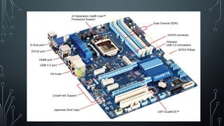
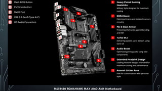
Preparing the Motherboardfor Installation:-
We should use a motherboard location map which shows where the hardware and major
components are located on the motherboard. It comes with the motherboard manual or inside
the motherboard box. If one don’t have this map , then he or she can also see or download it
from the motherboard manufacturer’s website.
Configuring the motherboard typically means the taking the
following steps:
Installing the CPU
Installing the heat sink and fan
installing RAM,
Connecting the power supply cables to the motherboard power connectors
Connecting miscellaneous connectors (like front USB, motherboard speaker for beep sound , front sound panel)
to the correct switches and status lights
and setting the
system BIOS.
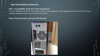
Steps To AssemblingA System/PC:-
Step 1: Compatibility Check All of Your Components
It is very important. If you do not make sure all of your components work together correctly you will not have a
working computer before you even start this project.
Step 2: Take Out Screws and Cover Off the Case
10.
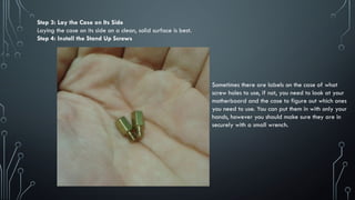
Step 3: Laythe Case on Its Side
Laying the case on its side on a clean, solid surface is best.
Step 4: Install the Stand Up Screws
Sometimes there are labels on the case of what
screw holes to use, if not, you need to look at your
motherboard and the case to figure out which ones
you need to use. You can put them in with only your
hands, however you should make sure they are in
securely with a small wrench.
11.
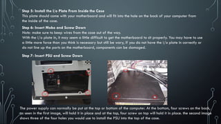
Step 5: Installthe I/o Plate From Inside the Case
This plate should come with your motherboard and will fit into the hole on the back of your computer from
the inside of the case.
Step 6: Insert Mobo and Screw Down
Note: make sure to keep wires from the case out of the way.
With the i/o plate in, it may seem a little difficult to get the motherboard to sit properly. You may have to use
a little more force than you think is necessary but still be wary, if you do not have the i/o plate in correctly or
do not line up the ports on the motherboard, components can be damaged.
Step 7: Insert PSU and Screw Down
The power supply can normally be put at the top or bottom of the computer. At the bottom, four screws on the back,
as seen in the first image, will hold it in place and at the top, four screw on top will hold it in place. the second image
shows three of the four holes you would use to install the PSU into the top of the case.
12.
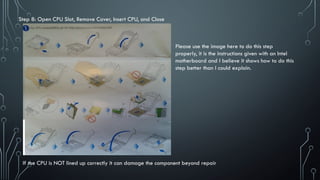
Step 8: OpenCPU Slot, Remove Cover, Insert CPU, and Close
If the CPU is NOT lined up correctly it can damage the component beyond repair
Please use the image here to do this step
properly, it is the instructions given with an Intel
motherboard and I believe it shows how to do this
step better than I could explain.
13.
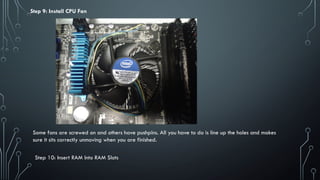
Step 9: InstallCPU Fan
Some fans are screwed on and others have pushpins. All you have to do is line up the holes and makes
sure it sits correctly unmoving when you are finished.
Step 10: Insert RAM Into RAM Slots
14.
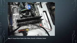
Step 11: InsertExtra Cards Like Video, Sound, or Wireless Cards
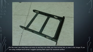
For the caseI am using there are easy to use bays you slide your hard drives into, as seen in the image. If you
are using multiple hard drives I suggest spacing them apart for maximum airflow.
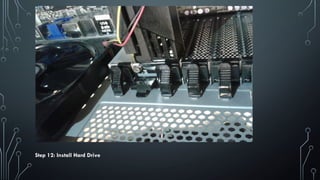
17.
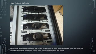
Step 13: InstallDVD Drive
for the case in the image, to install disc drives all you have to do is insert it from the front and push the
correct button which inserts the "screws" that would normally hold it in place.
18.
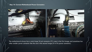
Step 14: ConnectMotherboard Power Connectors
The motherboard always has a main large 24 pin connector (P1), seen in the first image, and sometimes has
other smaller power connector like the one in the second image (4+4 Pin power connector).
19.
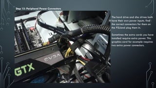
Step 15: PeripheralPower Connectors
The hard drive and disc drives both
have their own power inputs. find
the correct connectors for them on
the PSUand plug them in.
Sometimes the extra cards you have
installed require extra power. This
graphics card for example requires
two extra power connectors.
20.
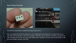
Step 16: Plugin Fan Cords
Your CPU fan should have a specific fan plug in spot near it.
Now you should find all the fan plug ins on your motherboard and decide how to attach the fans on
your case. The first image is what a fan connector looks like and the second is what they connect too. In
case of large case fan you may have male Molex power connector with your case fan & connect it with
your extra Molex connector from PSU.
21.
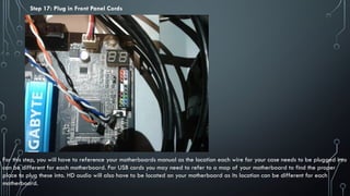
Step 17: Plugin Front Panel Cords
For this step, you will have to reference your motherboards manual as the location each wire for your case needs to be plugged into
can be different for each motherboard. For USB cords you may need to refer to a map of your motherboard to find the proper
place to plug these into. HD audio will also have to be located on your motherboard as its location can be different for each
motherboard.
22.
Step 18: Plugin Peripheral Cords
For your disc drives and hard drives you should need SATA data
cords which simply plug into the SATA ports on the motherboard.
An image is given as an example of a SATA cord.
Step 19: Plug in Wall Cord and Turn On
If your computer turns on and stays on, all your fans turn on, and all lights turn on correctly,
congratulations! You have just put together a working computer. You can now connect peripherals like a
mouse, keyboard and monitor and start installing your new OS system if you did not get a hard drive with
one.
23.
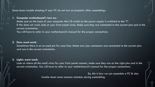
Some basic troubleshooting if your PC do not turn on properly after assembling:-
1. Computer motherboard's turn on:
Make sure on the back of your computer the I/0 switch on the power supply is switched to the “I”.
If this does not work, look at your front panel wires. Make sure they are connected to the correct pins and in the
correct orientation.
You will have to refer to your motherboard's manual for the proper connections.
2. Fans wont work:
Sometimes there is an un-used pin for case fans. Make sure your connectors are connected to the correct pins
and are in the correct orientation.
3. Lights wont work:
Look at where all the small wires for your front panel connect, make sure they are on the right pins and in the
correct orientation. You will have to refer to your motherboard’s manual for the proper connections.
So, this is how we can assemble a PC & also
trouble shoot some common mistakes during assembling.