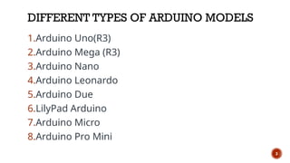
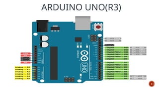
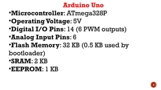
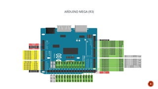
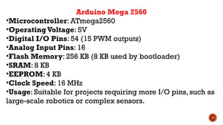
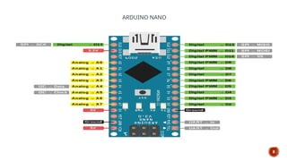
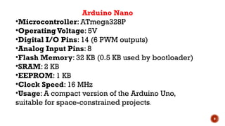
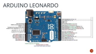
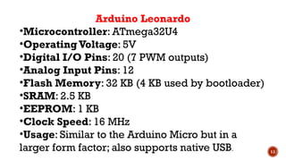
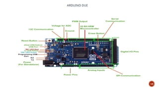
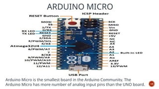
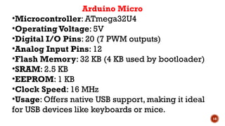
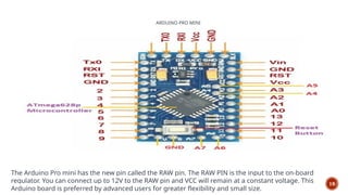
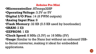
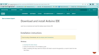
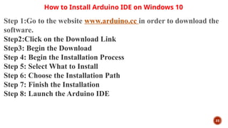
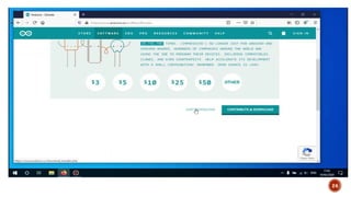
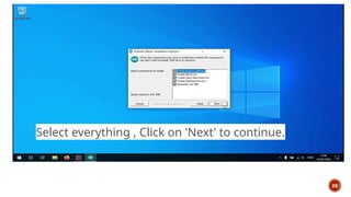
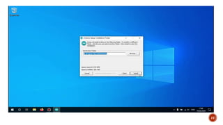
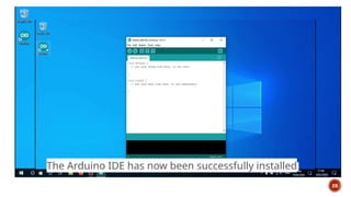
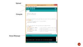
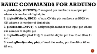
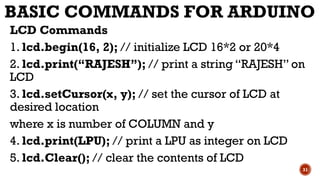
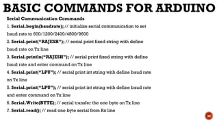
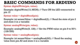
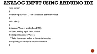
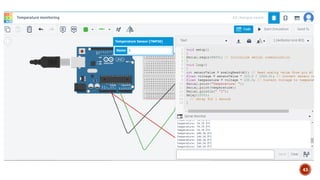
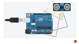
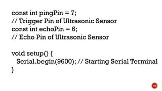
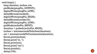
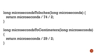
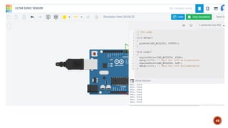
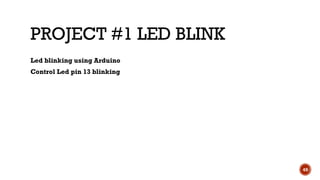
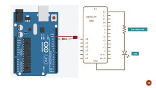
INTRODUCTION
TO ARDUINO
LIST OF TOPICS TO BE
COVERED
⮚Introduction to Arduino
⮚Arduino IDE
⮚Basic Commands
⮚Interfacing with Arduino
2
DIFFERENT TYPES OF ARDUINO MODELS
1.Arduino Uno(R3)
2.Arduino Mega (R3)
3.Arduino Nano
4.Arduino Leonardo
5.Arduino Due
6.LilyPad Arduino
7.Arduino Micro
8.Arduino Pro Mini
3
ARDUINO UNO(R3)
4
5
Arduino Uno
•Microcontroller: ATmega328P
•OperatingVoltage: 5V
•Digital I/O Pins: 14 (6 PWM outputs)
•Analog Input Pins: 6
•Flash Memory: 32 KB (0.5 KB used by
bootloader)
•SRAM: 2 KB
•EEPROM: 1 KB
ARDUINO MEGA (R3)
6
7
Arduino Mega 2560
•Microcontroller: ATmega2560
•OperatingVoltage: 5V
•Digital I/O Pins: 54 (15 PWM outputs)
•Analog Input Pins: 16
•Flash Memory: 256 KB (8 KB used by bootloader)
•SRAM: 8 KB
•EEPROM: 4 KB
•Clock Speed: 16 MHz
•Usage: Suitable for projects requiring more I/O pins, such as
large-scale robotics or complex sensors.
ARDUINO NANO
8
9
Arduino Nano
•Microcontroller: ATmega328P
•OperatingVoltage: 5V
•Digital I/O Pins: 14 (6 PWM outputs)
•Analog Input Pins: 8
•Flash Memory: 32 KB (0.5 KB used by bootloader)
•SRAM: 2 KB
•EEPROM: 1 KB
•Clock Speed: 16 MHz
•Usage: A compact version of the Arduino Uno,
suitable for space-constrained projects.
ARDUINO LEONARDO
10
11
Arduino Leonardo
•Microcontroller: ATmega32U4
•Operating Voltage: 5V
•Digital I/O Pins: 20 (7 PWM outputs)
•Analog Input Pins: 12
•Flash Memory: 32 KB (4 KB used by bootloader)
•SRAM: 2.5 KB
•EEPROM: 1 KB
•Clock Speed: 16 MHz
•Usage: Similar to the Arduino Micro but in a
larger form factor; also supports native USB.
ARDUINO DUE
12
13
Arduino Due is more preferable when there
are many peripherals that need to connect the
board. This board has many numbers of PWM
and ADC outputs so it can be more beneficial
to use the Due board where you will need
more PWM and ADC pins. It is the perfect
board for powerful larger scale Arduino
projects like designing complex systems like
CNC or 3D printer.
14
Arduino Due
•Microcontroller: Atmel SAM3X8E ARM Cortex-M3
•OperatingVoltage: 3.3V
•Digital I/O Pins: 54 (12 PWM outputs)
•Analog Input Pins: 12
•Analog Output Pins: 2 (DAC)
•Flash Memory: 512 KB
•SRAM: 96 KB
•Clock Speed: 84 MHz
•Usage: Suitable for more powerful applications, such as
complex calculations, or applications requiring high-speed
processing.
LILYPAD ARDUINO
15
Arduino Lilypad is very unique in its shape and
applications among the other Arduino boards.
This Arduino Lilypad is based on the circular
PCB with the wide holes at the corner and is
optimized for the e-textiles and wearable
projects. The Arduino Lilypad does not have
built-in USB to UART converter as it is present
in other Arduino modes.
16
ARDUINO MICRO
17
Arduino Micro is the smallest board in the Arduino Community. The
Arduino Micro has more number of analog input pins than the UNO board.
18
Arduino Micro
•Microcontroller: ATmega32U4
•Operating Voltage: 5V
•Digital I/O Pins: 20 (7 PWM outputs)
•Analog Input Pins: 12
•Flash Memory: 32 KB (4 KB used by bootloader)
•SRAM: 2.5 KB
•EEPROM: 1 KB
•Clock Speed: 16 MHz
•Usage: Offers native USB support, making it ideal
for USB devices like keyboards or mice.
ARDUINO PRO MINI
19
The Arduino Pro mini has the new pin called the RAW pin. The RAW PIN is the input to the on-board
regulator. You can connect up to 12V to the RAW pin and VCC will remain at a constant voltage. This
Arduino board is preferred by advanced users for greater flexibility and small size.
20
Arduino Pro Mini
•Microcontroller: ATmega328P
•OperatingVoltage: 3.3V or 5V
•Digital I/O Pins: 14 (6 PWM outputs)
•Analog Input Pins: 8
•Flash Memory: 32 KB (0.5 KB used by bootloader)
•SRAM: 2 KB
•EEPROM: 1 KB
•Clock Speed: 8 MHz (3.3V) or 16 MHz (5V)
•Usage: Similar to the Nano but without an onboard USB-
to-Serial converter, making it ideal for embedded
applications.
21
22
How to Install Arduino IDE on Windows 10
Step 1:Go to the website www.arduino.cc in order to download the
software.
Step2:Click on the Download Link
Step3: Begin the Download
Step 4: Begin the Installation Process
Step 5: Select What to Install
Step 6: Choose the Installation Path
Step 7: Finish the Installation
Step 8: Launch the Arduino IDE
23
24
25
Open the downloaded file.
A new window will open asking you to agree to the license
agreement.
Click on 'I agree' to continue.
26
Select everything , Click on 'Next' to continue.
27
28
The Arduino IDE has now been successfully installed.
29
Compile
Upload
Status Message
BASIC COMMANDS FOR ARDUINO
1. pinMode(x, OUTPUT); // assigned pin number x as output pin
where x is number of digital pin
2. digitalWrite(x, HIGH); // turn ON the pin number x as HIGH or
ON where x is number of digital pin
3. pinMode(x, INPUT); // assigned pin number x as input pin where
x is number of digital pin
4. digitalRead(digital Pin); // read the digital pin like 13 or 12 or 11
etc.
5. analogRead(analog pin); // read the analog pin like A0 or A1 or
A2 etc.
30
BASIC COMMANDS FOR ARDUINO
LCD Commands
1. lcd.begin(16, 2); // initialize LCD 16*2 or 20*4
2. lcd.print(“RAJESH”); // print a string “RAJESH” on
LCD
3. lcd.setCursor(x, y); // set the cursor of LCD at
desired location
where x is number of COLUMN and y
4. lcd.print(LPU); // print a LPU as integer on LCD
5. lcd.Clear(); // clear the contents of LCD
31
BASIC COMMANDS FOR ARDUINO
Serial Communication Commands
1. Serial.begin(baudrate); // initialize serial communication to set
baud rate to 600/1200/2400/4800/9600
2. Serial.print(“RAJESH”); // serial print fixed string with define
baud rate on Tx line
3. Serial.println(“RAJESH”); // serial print fixed string with define
baud rate and enter command on Tx line
4. Serial.print(“LPU”); // serial print int string with define baud rate
on Tx line
5. Serial.print(“LPU”); // serial print int string with define baud rate
and enter command on Tx line
6. Serial.Write(BYTE); // serial transfer the one byte on Tx line
7. Serial.read(); // read one byte serial from Rx line
32
BASIC COMMANDS FOR ARDUINO
Syntax: digitalWrite(pin, value);
Example: digitalWrite(13, HIGH); // Turn ON the LED connected to
pin 13
Syntax: value = digitalRead(pin);
Example: int sensorValue = digitalRead(2); // Read the state of pin 2
and store it in a variable
Syntax: analogWrite(pin, value);
Example: analogWrite(9, 128); // Set the PWM value on pin 9 to 50%
(128/255)
Syntax: value = analogRead(pin);
Example: int sensorValue = analogRead(A0); // Read the analog
value from pin A0 and store it in a variable
33
ANALOG INPUT USING ARDUINO IDE
void setup()
{
Serial.begin(9600); // Initialize serial communication
}
void loop()
{
int sensorValue = analogRead(A0);
// Read analog input from pin A0
Serial.println(sensorValue);
// Print the sensor value to the serial monitor
delay(500); // Delay for 500 milliseconds
}
34
ANALOG INPUT USING ARDUINO IDE
35
36
37
38
READING ANDWRITING DIGITAL AND ANALOG VALUES:
Interfacing a Temperature Sensor with Arduino
39
40
void setup()
{
Serial.begin(9600); // Initialize serial communication
}
void loop()
{
int sensorValue = analogRead(A0); // Read analog value from pin A0
float voltage = sensorValue * (5.0 / 1023.0); // Convert sensor value to voltage
float temperature = voltage * 100.0; // Convert voltage to temperature in Celsius
Serial.print("Temperature: ");
Serial.print(temperature);
Serial.println(" °C");
delay(1000); // Delay for 1 second
}
41
42
43
44
45
const int pingPin = 7;
// Trigger Pin of Ultrasonic Sensor
const int echoPin = 6;
// Echo Pin of Ultrasonic Sensor
void setup() {
Serial.begin(9600); // Starting Serial Terminal
}
46
void loop() {
long duration, inches, cm;
pinMode(pingPin, OUTPUT);
digitalWrite(pingPin, LOW);
delayMicroseconds(2);
digitalWrite(pingPin, HIGH);
delayMicroseconds(10);
digitalWrite(pingPin, LOW);
pinMode(echoPin, INPUT);
duration = pulseIn(echoPin, HIGH);
inches = microsecondsToInches(duration);
cm = microsecondsToCentimeters(duration);
Serial.print(inches);
Serial.print("in, ");
Serial.print(cm);
Serial.print("cm");
Serial.println();
delay(100);
47
long microsecondsToInches(long microseconds) {
return microseconds / 74 / 2;
}
long microsecondsToCentimeters(long microseconds)
{
return microseconds / 29 / 2;
}
48
PROJECT #1 LED BLINK
49
Led blinking using Arduino
Control Led pin 13 blinking
50
▪ First, the program will use the pinMode function to declare pin 13 as an output pin.
Next, use the digitalWrite function to control the led on or off.The delay function is
used to delay the program for a specific time and then execute the next instructions.
// the setup function runs once
void setup() {
// initialize digital pin 13 as an output.
pinMode(13,OUTPUT);
}
// the loop function runs over and over again forever
void loop() {
// turn the LED on (HIGH is the voltage level)
digitalWrite(13,HIGH);
delay(1000); // wait for a second
// turn the LED off by making the voltage LOW
digitalWrite(13,LOW);
delay(1000); // wait for a second
} 51
Three leds blink
The circuit uses three output pins 11, 12, and 13 of the Arduino to control three LEDs blinking.The connection diagram is similar to that in the example above.
// the setup function runs once
void setup() {
// initialize digital pin 11, 12, 13 as an output.
pinMode(11, OUTPUT);
pinMode(12, OUTPUT);
pinMode(13, OUTPUT);
}
// the loop function runs over and over again forever
void loop() {
// turn the LED on
digitalWrite(11, HIGH);
digitalWrite(12, HIGH);
digitalWrite(13, HIGH);
delay(1000); // wait for a second
// turn the LED off
digitalWrite(11, LOW);
digitalWrite(12, LOW);
digitalWrite(13, LOW);
delay(1000); // wait for a second
}
52
Arduino blink led 5 times
▪In this example, we will control a red led to blink 5 times using Arduino.Then the red led will turn
off, and the yellow led turns on to indicate the end of the program. Red led connected to pin 13;
yellow led connected to pin 12 (refer to the circuit diagram in simulation video below).
▪In the setup function, we declare a subroutine called blink5times.The main program will not use
any statements.
▪In the blink5times subroutine, we use For function to repeat the control functions to turn the red
led on and off five times.Then turn on the yellow led to indicate the end of the program.
53
// the setup function runs once
void setup() {
// initialize digital pin 12, 13 as an output.
pinMode(12, OUTPUT);
pinMode(13, OUTPUT);
blink5times();
}
// the loop function runs over and over again forever
void loop() {
//
}
void blink5times(){
for (int i=0; i<5; i=i+1){
digitalWrite(13, HIGH); // turn the LED on
delay(500); // wait for a half second
digitalWrite(13, LOW); // turn the LED off
delay(500); // wait for a half second
} 54
THANKYOU
▪https://www.youtube.com/watch?v=vHqJMwmj3-8 (IoT Project Using Arduino
Uno WithoutWi-Fi module | Blynk Tutorial )
56
https://support.arduino.cc/hc/en-us/articles/360019833020-Download-and-install-A
rduino-IDE
https://canthoautomation.com/led-blinking-using-arduino/
57

Arduino . .

  • 1.
  • 2.
    LIST OF TOPICSTO BE COVERED ⮚Introduction to Arduino ⮚Arduino IDE ⮚Basic Commands ⮚Interfacing with Arduino 2
  • 3.
    DIFFERENT TYPES OFARDUINO MODELS 1.Arduino Uno(R3) 2.Arduino Mega (R3) 3.Arduino Nano 4.Arduino Leonardo 5.Arduino Due 6.LilyPad Arduino 7.Arduino Micro 8.Arduino Pro Mini 3
  • 4.
  • 5.
    5 Arduino Uno •Microcontroller: ATmega328P •OperatingVoltage:5V •Digital I/O Pins: 14 (6 PWM outputs) •Analog Input Pins: 6 •Flash Memory: 32 KB (0.5 KB used by bootloader) •SRAM: 2 KB •EEPROM: 1 KB
  • 6.
  • 7.
    7 Arduino Mega 2560 •Microcontroller:ATmega2560 •OperatingVoltage: 5V •Digital I/O Pins: 54 (15 PWM outputs) •Analog Input Pins: 16 •Flash Memory: 256 KB (8 KB used by bootloader) •SRAM: 8 KB •EEPROM: 4 KB •Clock Speed: 16 MHz •Usage: Suitable for projects requiring more I/O pins, such as large-scale robotics or complex sensors.
  • 8.
  • 9.
    9 Arduino Nano •Microcontroller: ATmega328P •OperatingVoltage:5V •Digital I/O Pins: 14 (6 PWM outputs) •Analog Input Pins: 8 •Flash Memory: 32 KB (0.5 KB used by bootloader) •SRAM: 2 KB •EEPROM: 1 KB •Clock Speed: 16 MHz •Usage: A compact version of the Arduino Uno, suitable for space-constrained projects.
  • 10.
  • 11.
    11 Arduino Leonardo •Microcontroller: ATmega32U4 •OperatingVoltage: 5V •Digital I/O Pins: 20 (7 PWM outputs) •Analog Input Pins: 12 •Flash Memory: 32 KB (4 KB used by bootloader) •SRAM: 2.5 KB •EEPROM: 1 KB •Clock Speed: 16 MHz •Usage: Similar to the Arduino Micro but in a larger form factor; also supports native USB.
  • 12.
  • 13.
    13 Arduino Due ismore preferable when there are many peripherals that need to connect the board. This board has many numbers of PWM and ADC outputs so it can be more beneficial to use the Due board where you will need more PWM and ADC pins. It is the perfect board for powerful larger scale Arduino projects like designing complex systems like CNC or 3D printer.
  • 14.
    14 Arduino Due •Microcontroller: AtmelSAM3X8E ARM Cortex-M3 •OperatingVoltage: 3.3V •Digital I/O Pins: 54 (12 PWM outputs) •Analog Input Pins: 12 •Analog Output Pins: 2 (DAC) •Flash Memory: 512 KB •SRAM: 96 KB •Clock Speed: 84 MHz •Usage: Suitable for more powerful applications, such as complex calculations, or applications requiring high-speed processing.
  • 15.
  • 16.
    Arduino Lilypad isvery unique in its shape and applications among the other Arduino boards. This Arduino Lilypad is based on the circular PCB with the wide holes at the corner and is optimized for the e-textiles and wearable projects. The Arduino Lilypad does not have built-in USB to UART converter as it is present in other Arduino modes. 16
  • 17.
    ARDUINO MICRO 17 Arduino Microis the smallest board in the Arduino Community. The Arduino Micro has more number of analog input pins than the UNO board.
  • 18.
    18 Arduino Micro •Microcontroller: ATmega32U4 •OperatingVoltage: 5V •Digital I/O Pins: 20 (7 PWM outputs) •Analog Input Pins: 12 •Flash Memory: 32 KB (4 KB used by bootloader) •SRAM: 2.5 KB •EEPROM: 1 KB •Clock Speed: 16 MHz •Usage: Offers native USB support, making it ideal for USB devices like keyboards or mice.
  • 19.
    ARDUINO PRO MINI 19 TheArduino Pro mini has the new pin called the RAW pin. The RAW PIN is the input to the on-board regulator. You can connect up to 12V to the RAW pin and VCC will remain at a constant voltage. This Arduino board is preferred by advanced users for greater flexibility and small size.
  • 20.
    20 Arduino Pro Mini •Microcontroller:ATmega328P •OperatingVoltage: 3.3V or 5V •Digital I/O Pins: 14 (6 PWM outputs) •Analog Input Pins: 8 •Flash Memory: 32 KB (0.5 KB used by bootloader) •SRAM: 2 KB •EEPROM: 1 KB •Clock Speed: 8 MHz (3.3V) or 16 MHz (5V) •Usage: Similar to the Nano but without an onboard USB- to-Serial converter, making it ideal for embedded applications.
  • 21.
  • 22.
    22 How to InstallArduino IDE on Windows 10 Step 1:Go to the website www.arduino.cc in order to download the software. Step2:Click on the Download Link Step3: Begin the Download Step 4: Begin the Installation Process Step 5: Select What to Install Step 6: Choose the Installation Path Step 7: Finish the Installation Step 8: Launch the Arduino IDE
  • 23.
  • 24.
  • 25.
    25 Open the downloadedfile. A new window will open asking you to agree to the license agreement. Click on 'I agree' to continue.
  • 26.
    26 Select everything ,Click on 'Next' to continue.
  • 27.
  • 28.
    28 The Arduino IDEhas now been successfully installed.
  • 29.
  • 30.
    BASIC COMMANDS FORARDUINO 1. pinMode(x, OUTPUT); // assigned pin number x as output pin where x is number of digital pin 2. digitalWrite(x, HIGH); // turn ON the pin number x as HIGH or ON where x is number of digital pin 3. pinMode(x, INPUT); // assigned pin number x as input pin where x is number of digital pin 4. digitalRead(digital Pin); // read the digital pin like 13 or 12 or 11 etc. 5. analogRead(analog pin); // read the analog pin like A0 or A1 or A2 etc. 30
  • 31.
    BASIC COMMANDS FORARDUINO LCD Commands 1. lcd.begin(16, 2); // initialize LCD 16*2 or 20*4 2. lcd.print(“RAJESH”); // print a string “RAJESH” on LCD 3. lcd.setCursor(x, y); // set the cursor of LCD at desired location where x is number of COLUMN and y 4. lcd.print(LPU); // print a LPU as integer on LCD 5. lcd.Clear(); // clear the contents of LCD 31
  • 32.
    BASIC COMMANDS FORARDUINO Serial Communication Commands 1. Serial.begin(baudrate); // initialize serial communication to set baud rate to 600/1200/2400/4800/9600 2. Serial.print(“RAJESH”); // serial print fixed string with define baud rate on Tx line 3. Serial.println(“RAJESH”); // serial print fixed string with define baud rate and enter command on Tx line 4. Serial.print(“LPU”); // serial print int string with define baud rate on Tx line 5. Serial.print(“LPU”); // serial print int string with define baud rate and enter command on Tx line 6. Serial.Write(BYTE); // serial transfer the one byte on Tx line 7. Serial.read(); // read one byte serial from Rx line 32
  • 33.
    BASIC COMMANDS FORARDUINO Syntax: digitalWrite(pin, value); Example: digitalWrite(13, HIGH); // Turn ON the LED connected to pin 13 Syntax: value = digitalRead(pin); Example: int sensorValue = digitalRead(2); // Read the state of pin 2 and store it in a variable Syntax: analogWrite(pin, value); Example: analogWrite(9, 128); // Set the PWM value on pin 9 to 50% (128/255) Syntax: value = analogRead(pin); Example: int sensorValue = analogRead(A0); // Read the analog value from pin A0 and store it in a variable 33
  • 34.
    ANALOG INPUT USINGARDUINO IDE void setup() { Serial.begin(9600); // Initialize serial communication } void loop() { int sensorValue = analogRead(A0); // Read analog input from pin A0 Serial.println(sensorValue); // Print the sensor value to the serial monitor delay(500); // Delay for 500 milliseconds } 34
  • 35.
    ANALOG INPUT USINGARDUINO IDE 35
  • 36.
  • 37.
  • 38.
  • 39.
    READING ANDWRITING DIGITALAND ANALOG VALUES: Interfacing a Temperature Sensor with Arduino 39
  • 40.
  • 41.
    void setup() { Serial.begin(9600); //Initialize serial communication } void loop() { int sensorValue = analogRead(A0); // Read analog value from pin A0 float voltage = sensorValue * (5.0 / 1023.0); // Convert sensor value to voltage float temperature = voltage * 100.0; // Convert voltage to temperature in Celsius Serial.print("Temperature: "); Serial.print(temperature); Serial.println(" °C"); delay(1000); // Delay for 1 second } 41
  • 42.
  • 43.
  • 44.
  • 45.
    45 const int pingPin= 7; // Trigger Pin of Ultrasonic Sensor const int echoPin = 6; // Echo Pin of Ultrasonic Sensor void setup() { Serial.begin(9600); // Starting Serial Terminal }
  • 46.
    46 void loop() { longduration, inches, cm; pinMode(pingPin, OUTPUT); digitalWrite(pingPin, LOW); delayMicroseconds(2); digitalWrite(pingPin, HIGH); delayMicroseconds(10); digitalWrite(pingPin, LOW); pinMode(echoPin, INPUT); duration = pulseIn(echoPin, HIGH); inches = microsecondsToInches(duration); cm = microsecondsToCentimeters(duration); Serial.print(inches); Serial.print("in, "); Serial.print(cm); Serial.print("cm"); Serial.println(); delay(100);
  • 47.
    47 long microsecondsToInches(long microseconds){ return microseconds / 74 / 2; } long microsecondsToCentimeters(long microseconds) { return microseconds / 29 / 2; }
  • 48.
  • 49.
    PROJECT #1 LEDBLINK 49 Led blinking using Arduino Control Led pin 13 blinking
  • 50.
  • 51.
    ▪ First, theprogram will use the pinMode function to declare pin 13 as an output pin. Next, use the digitalWrite function to control the led on or off.The delay function is used to delay the program for a specific time and then execute the next instructions. // the setup function runs once void setup() { // initialize digital pin 13 as an output. pinMode(13,OUTPUT); } // the loop function runs over and over again forever void loop() { // turn the LED on (HIGH is the voltage level) digitalWrite(13,HIGH); delay(1000); // wait for a second // turn the LED off by making the voltage LOW digitalWrite(13,LOW); delay(1000); // wait for a second } 51
  • 52.
    Three leds blink Thecircuit uses three output pins 11, 12, and 13 of the Arduino to control three LEDs blinking.The connection diagram is similar to that in the example above. // the setup function runs once void setup() { // initialize digital pin 11, 12, 13 as an output. pinMode(11, OUTPUT); pinMode(12, OUTPUT); pinMode(13, OUTPUT); } // the loop function runs over and over again forever void loop() { // turn the LED on digitalWrite(11, HIGH); digitalWrite(12, HIGH); digitalWrite(13, HIGH); delay(1000); // wait for a second // turn the LED off digitalWrite(11, LOW); digitalWrite(12, LOW); digitalWrite(13, LOW); delay(1000); // wait for a second } 52
  • 53.
    Arduino blink led5 times ▪In this example, we will control a red led to blink 5 times using Arduino.Then the red led will turn off, and the yellow led turns on to indicate the end of the program. Red led connected to pin 13; yellow led connected to pin 12 (refer to the circuit diagram in simulation video below). ▪In the setup function, we declare a subroutine called blink5times.The main program will not use any statements. ▪In the blink5times subroutine, we use For function to repeat the control functions to turn the red led on and off five times.Then turn on the yellow led to indicate the end of the program. 53
  • 54.
    // the setupfunction runs once void setup() { // initialize digital pin 12, 13 as an output. pinMode(12, OUTPUT); pinMode(13, OUTPUT); blink5times(); } // the loop function runs over and over again forever void loop() { // } void blink5times(){ for (int i=0; i<5; i=i+1){ digitalWrite(13, HIGH); // turn the LED on delay(500); // wait for a half second digitalWrite(13, LOW); // turn the LED off delay(500); // wait for a half second } 54
  • 55.
  • 56.
    ▪https://www.youtube.com/watch?v=vHqJMwmj3-8 (IoT ProjectUsing Arduino Uno WithoutWi-Fi module | Blynk Tutorial ) 56
  • 57.