App152 en measurement-railroad-rails-laser-profile-sensors
1. A152_e
2D/3D profile sensor
scanCONTROL2800
Measurement of railroad rails with laser profile sensors
Guaranteeing the safety and stability of railroads
when transporting persons or goods nowadays
plays a significant role. In this respect the track is an
important link in the chain. The increased loading of
the rail network and the higher speeds of modern
trains lead to higher stressing of the rails. The state of
the tracks must be inspected regularly to prevent
costly incidents.
The wear of the rail head is an important parameter in
reliably assessing the state of the rails. If the wear is
too high, this can lead in the worst case to train
derailments.
Conventional inspection methods are based on
visual manual inspections. This procedure is how-
ever fraught with disadvantages: too slow, too
inaccurate and therefore inefficient.
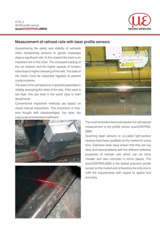
The most innovative technical solution for railroad rail
measurement is the profile sensor scanCONTROL
2800.
Scanning laser sensors or so-called light-section
sensors have been available on the market for some
time. Extensive tests have shown that they are too
slow and have problems with the different reflective
properties of railroad rails which can be shiny
metallic and also corroded in some places. The
scanCONTROL2800 is the fastest precision profile
sensor on the market and is therefore the only one to
fulfill the requirements with regard to speed and
accuracy.
2. Application
Procedure for railroad rail measurement System set-up
The measurement occurs without contact and it is 1. Per rail 2 x LLT2800-100(205), i.e. 4 sensor
very accurate and fast. To be able to acquire the systems per inspection car.
whole profile of the rail head two LLT sensors are 2. Measurement computer and evaluation software
required. Per inspection car four systems are supplied by the customer.
employed which are synchronized to each other.
The measurements take place at speeds of up to 100 Decisive advantages for the customer
km/h. 1. Fast measurement rate saves time and therefore
In the measurement computer an ideal profile is costs.
saved which is continually compared to the measu- 2. Higher accuracy than the previous subjective
red profile. If the preset tolerances are exceeded, the visual inspection.
rail is classed as unsafe and marked in the PC. 3. Fire-Wire interface enables a fast transfer of
measurement data.
Measurement system requirements 4. Customized adaptations (larger focusing distan-
Measurement range X = 125 mm ce, laser with 50 mW) lead to optimum results
Measurement range Z = 50 mm with this special measurement application.
Base distance 230 mm;
Sensor with modified focusing distance.
Dynamic response: 2000 profiles/s each with 128
scanCONTROL scanCONTROL
measurement points
z-ax
Laser: 50 mW, class 3 B
is
Ambient conditions
Temperature: -20 to +80 °C
xis
x-a
(Special protective housing with heating for use in
sub-zero temperatures.)
Harsh ambient conditions; since the sensor is fitted
to the underside of the car, it is subjected to the
widest range of weather conditions and vibrations.
Two synchronized profile sensors acquire the track profile
to determine the wear.
MICRO-EPSILON A member of micro-epsilon group.
Koenigbacher Str. 15 Tel.: +49 (0) 85 42/1 68-0 info@micro-epsilon.com Certified DIN EN ISO 9001 : 2000
94496 Ortenburg / Germany Fax: +49 (0) 85 42/1 68 90 www.micro-epsilon.com Modifications reserved Y9781152