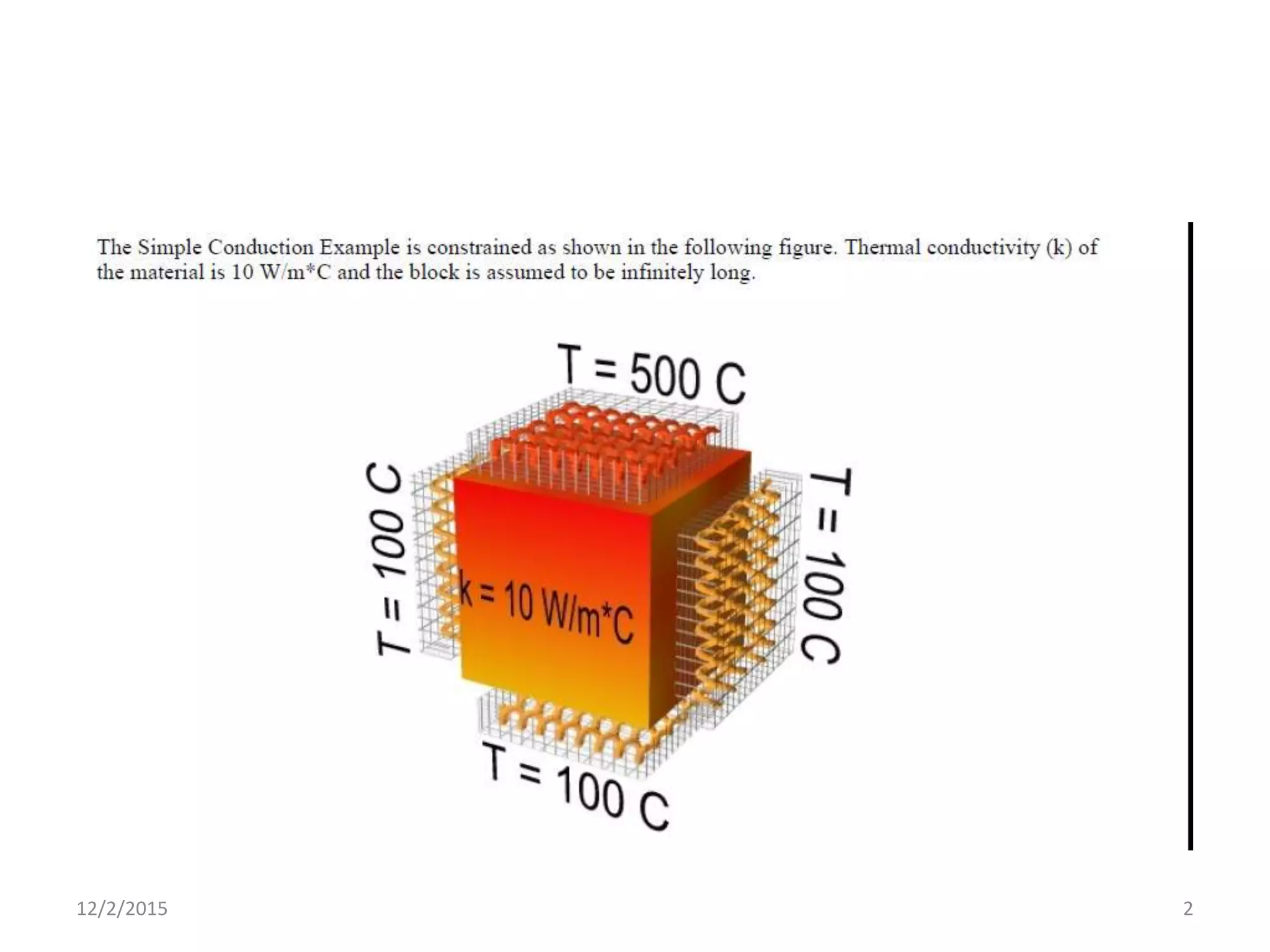
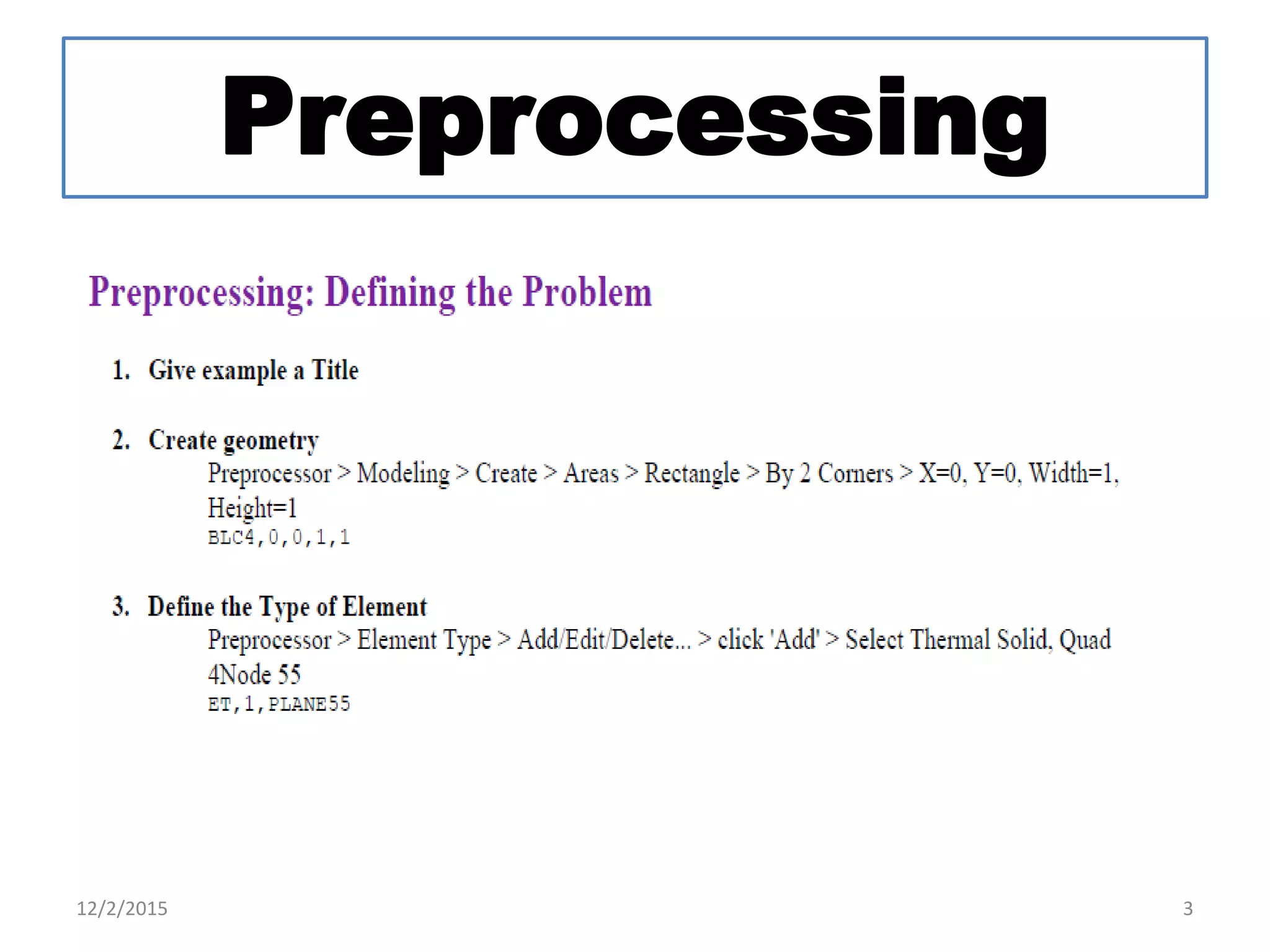
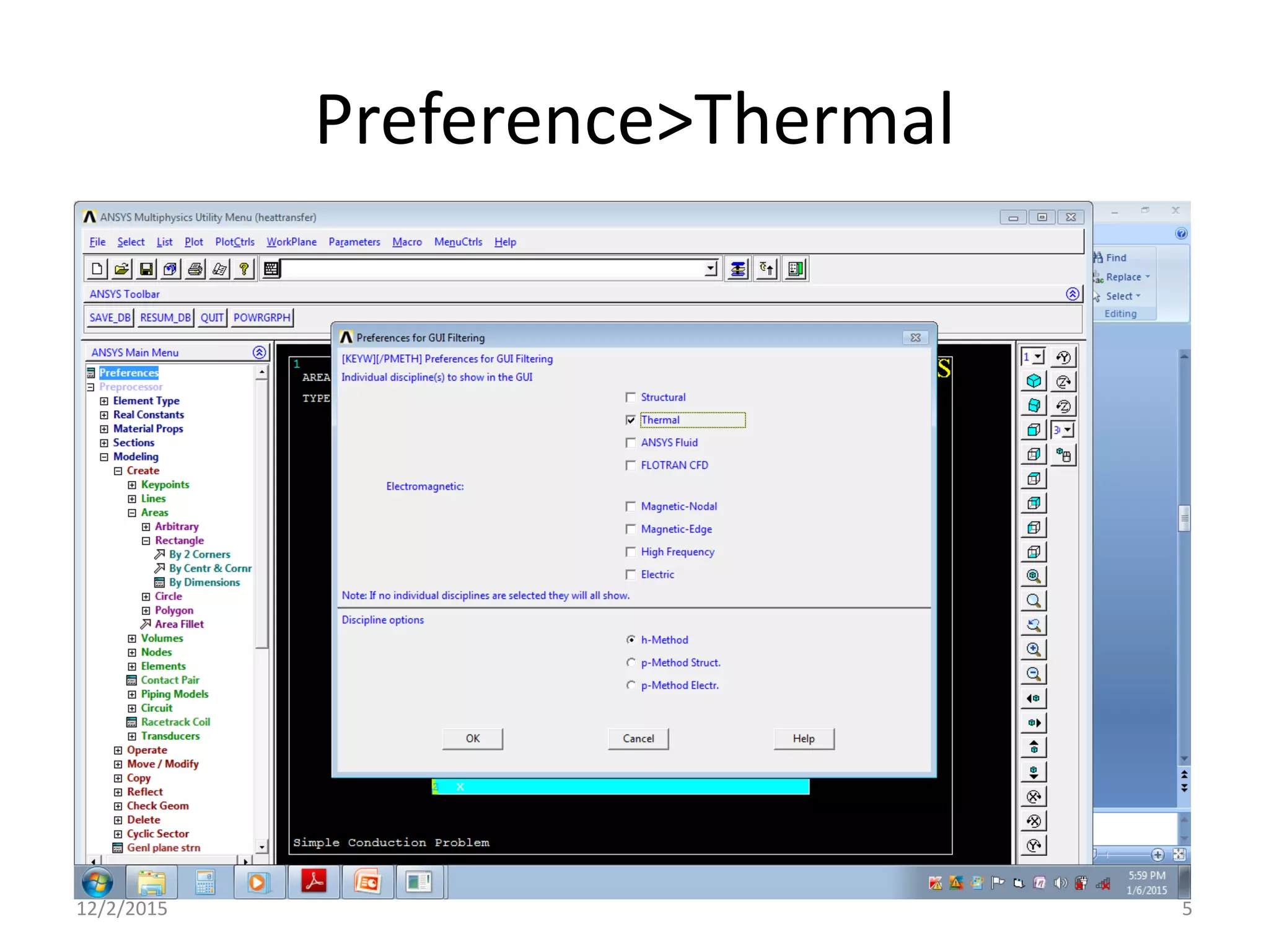
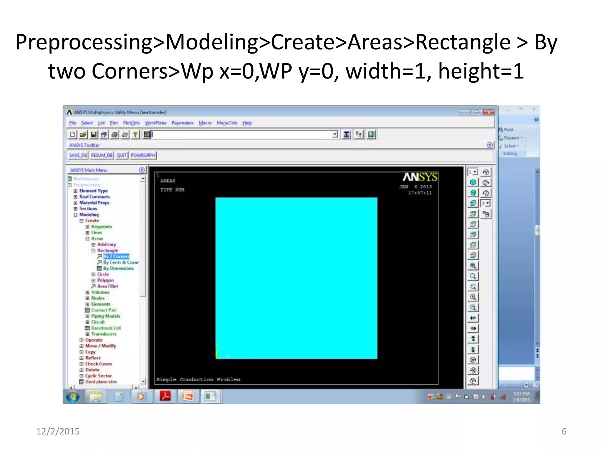
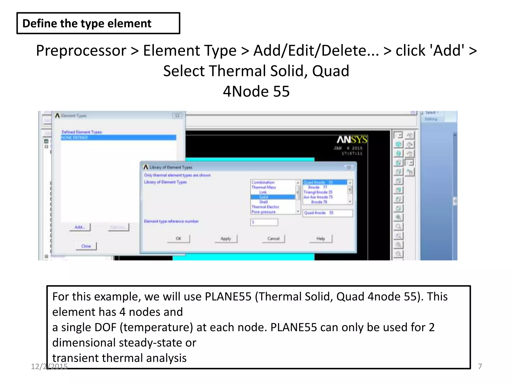
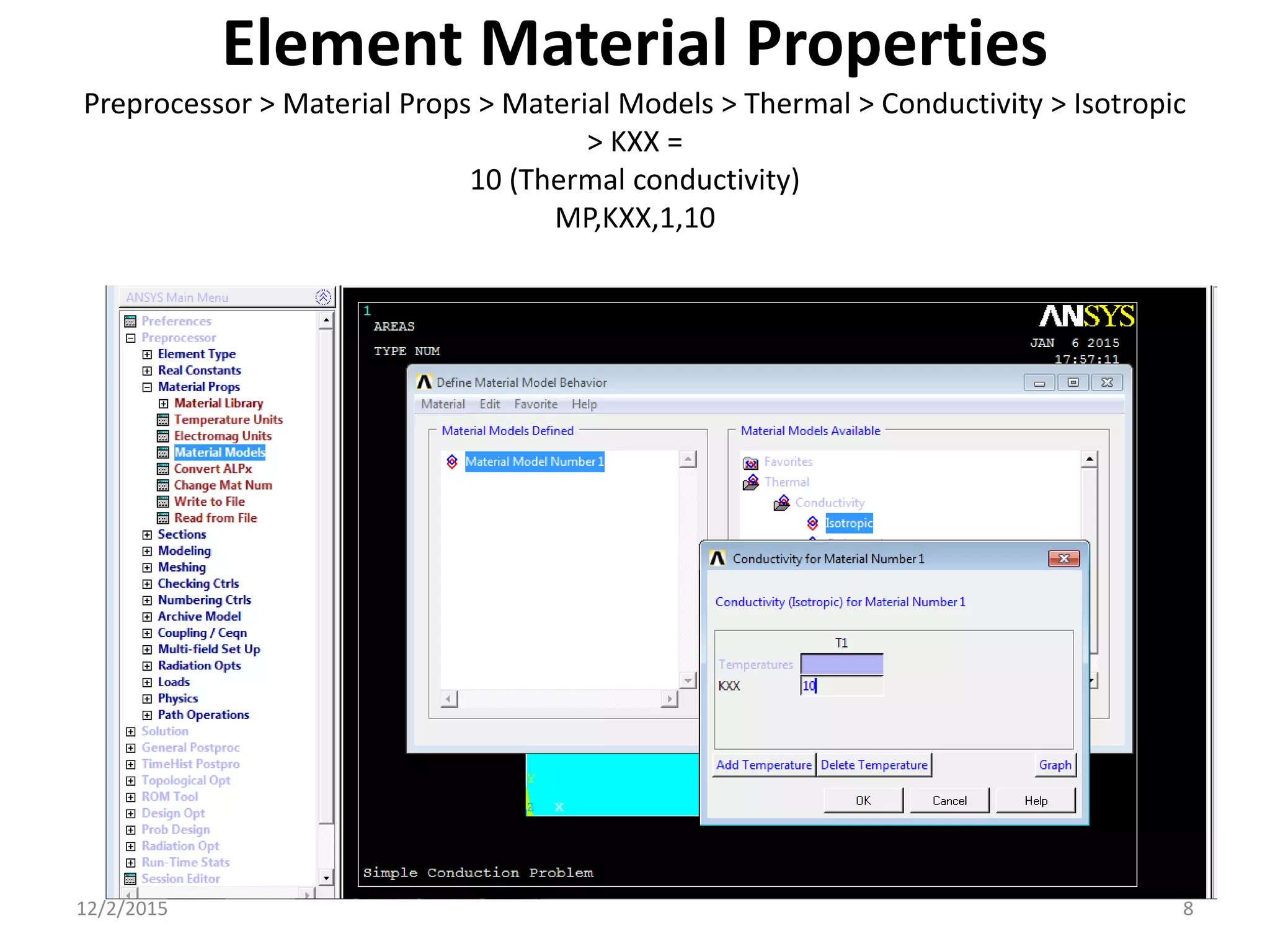
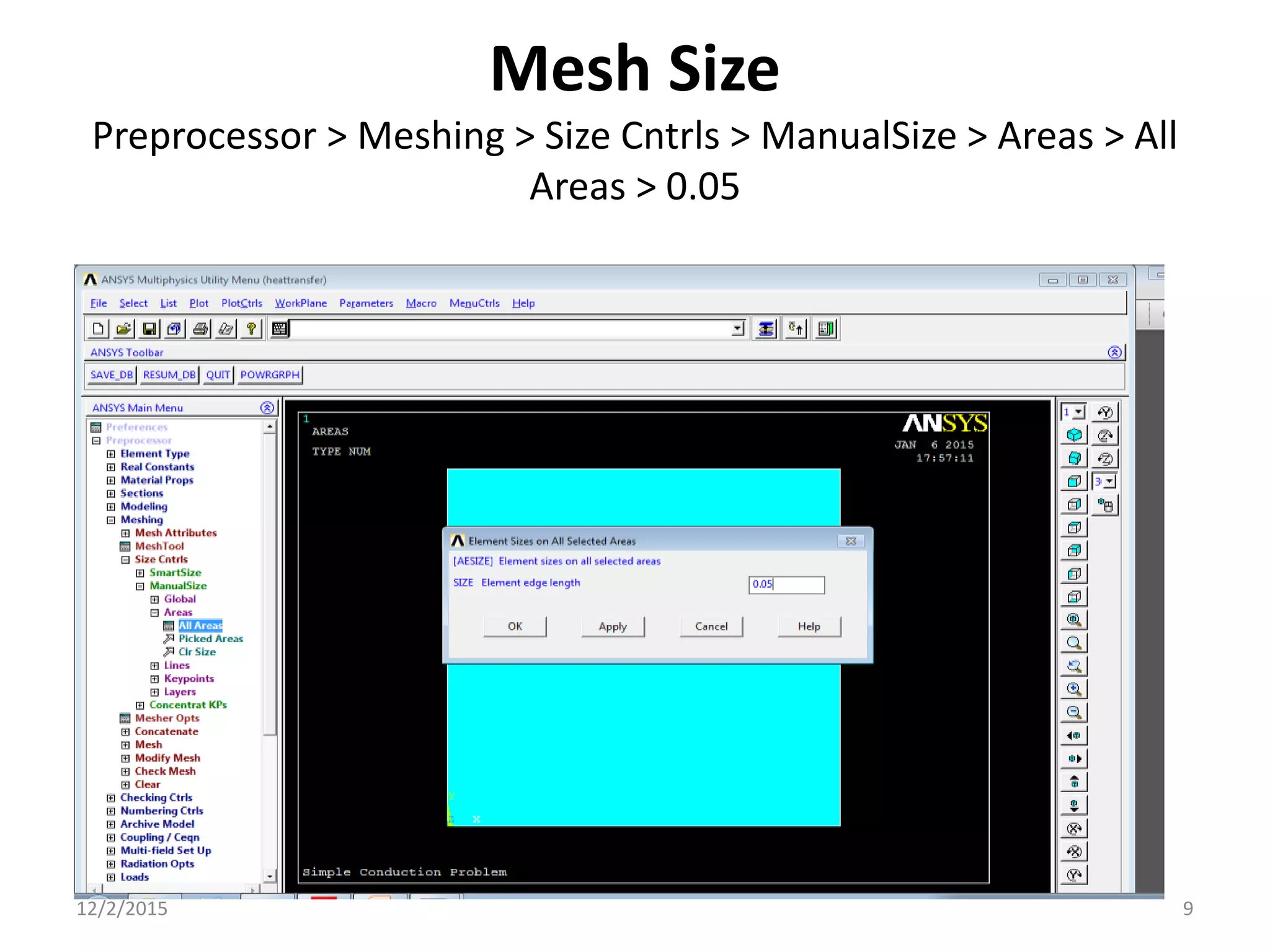
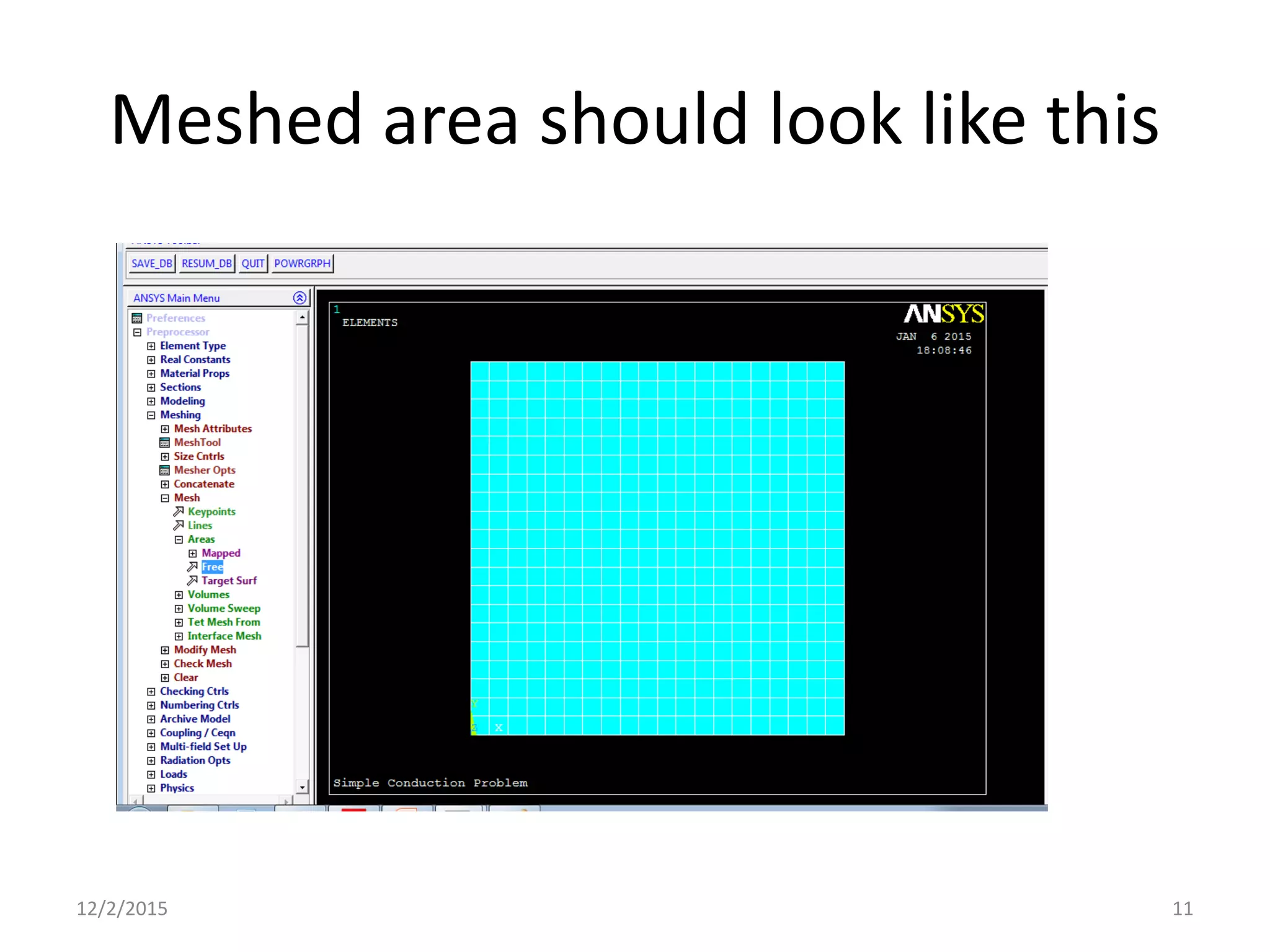
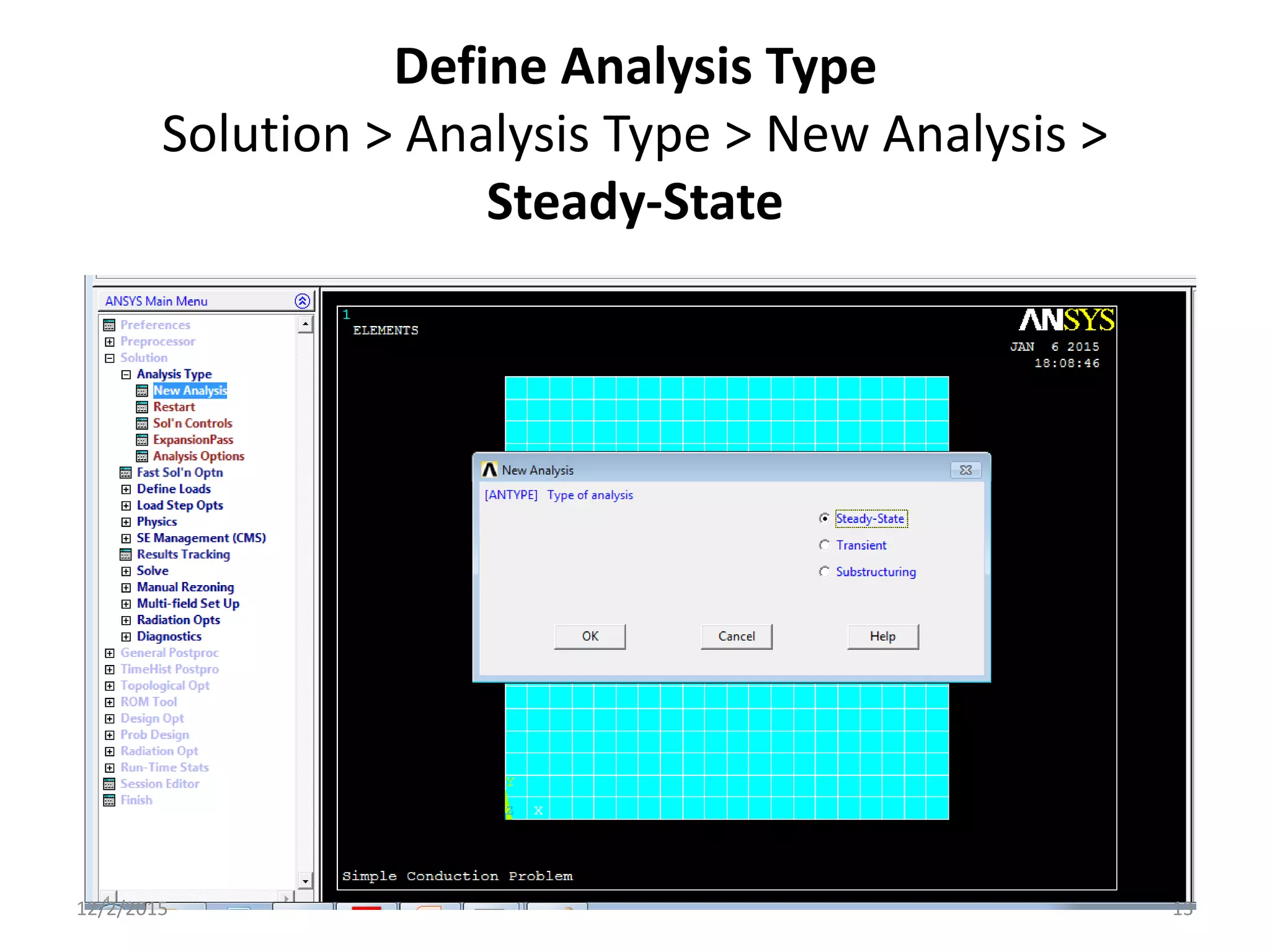
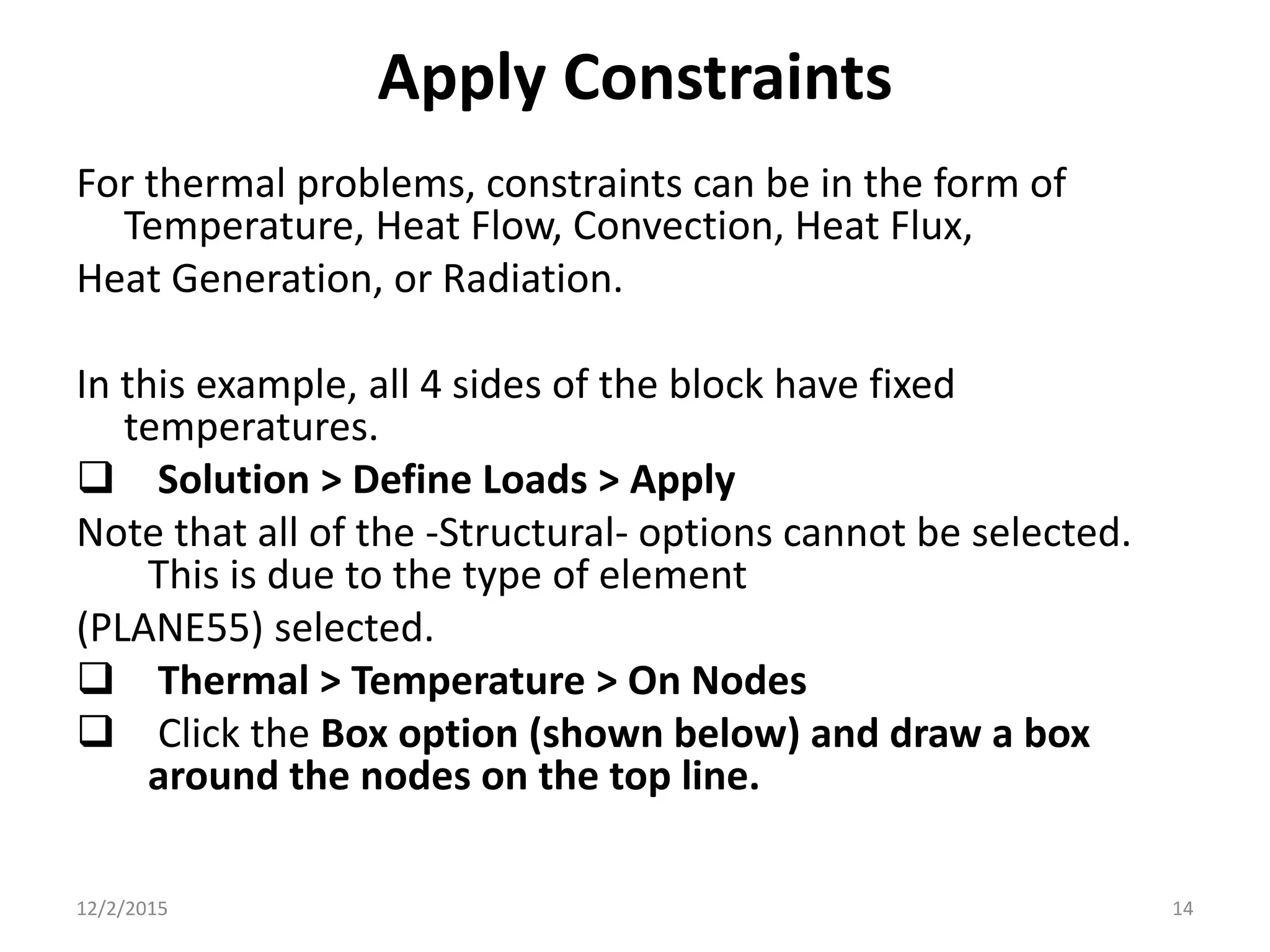
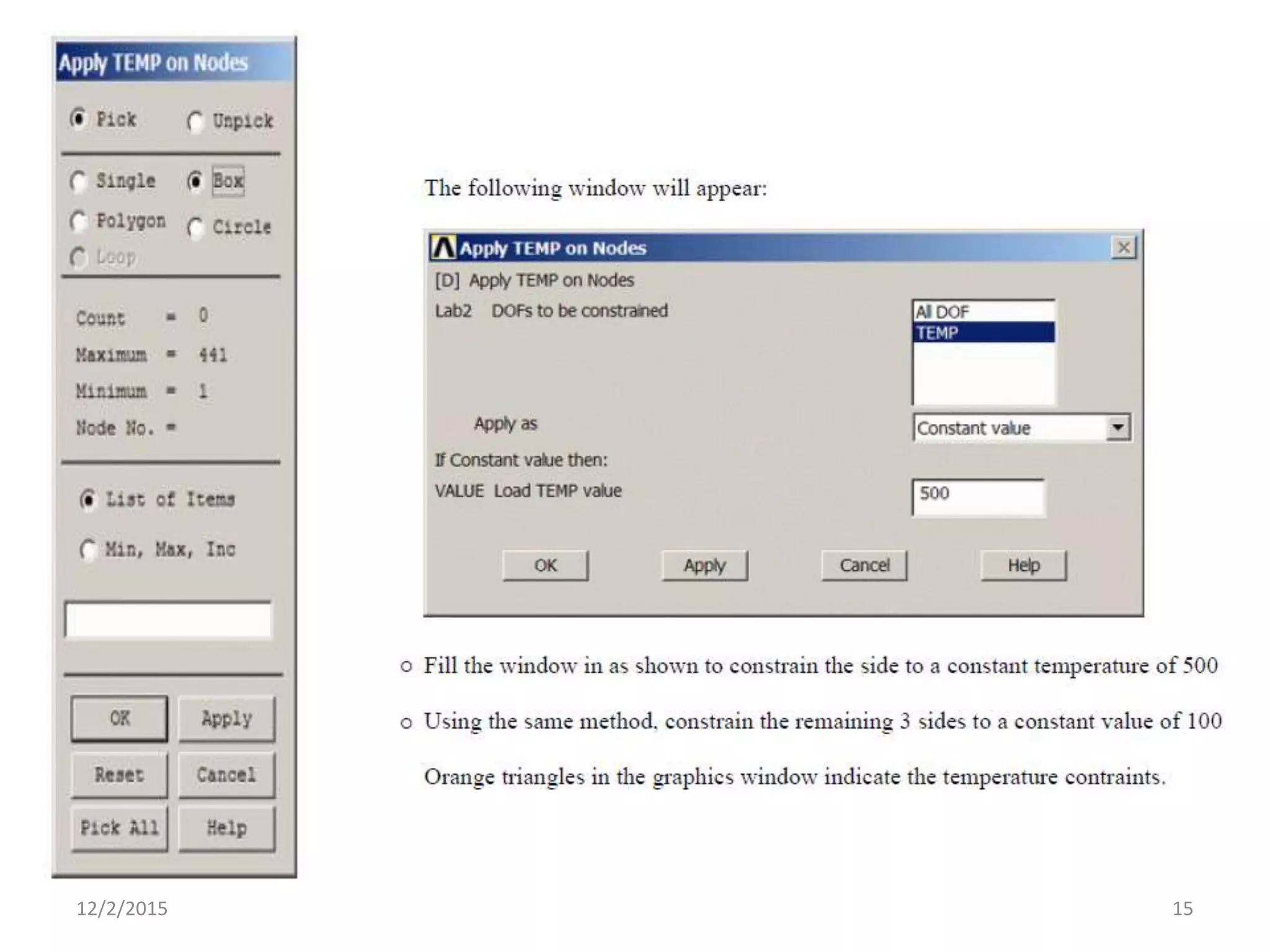
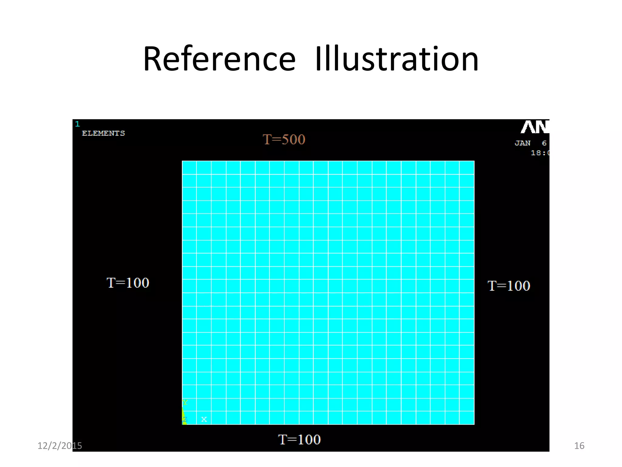
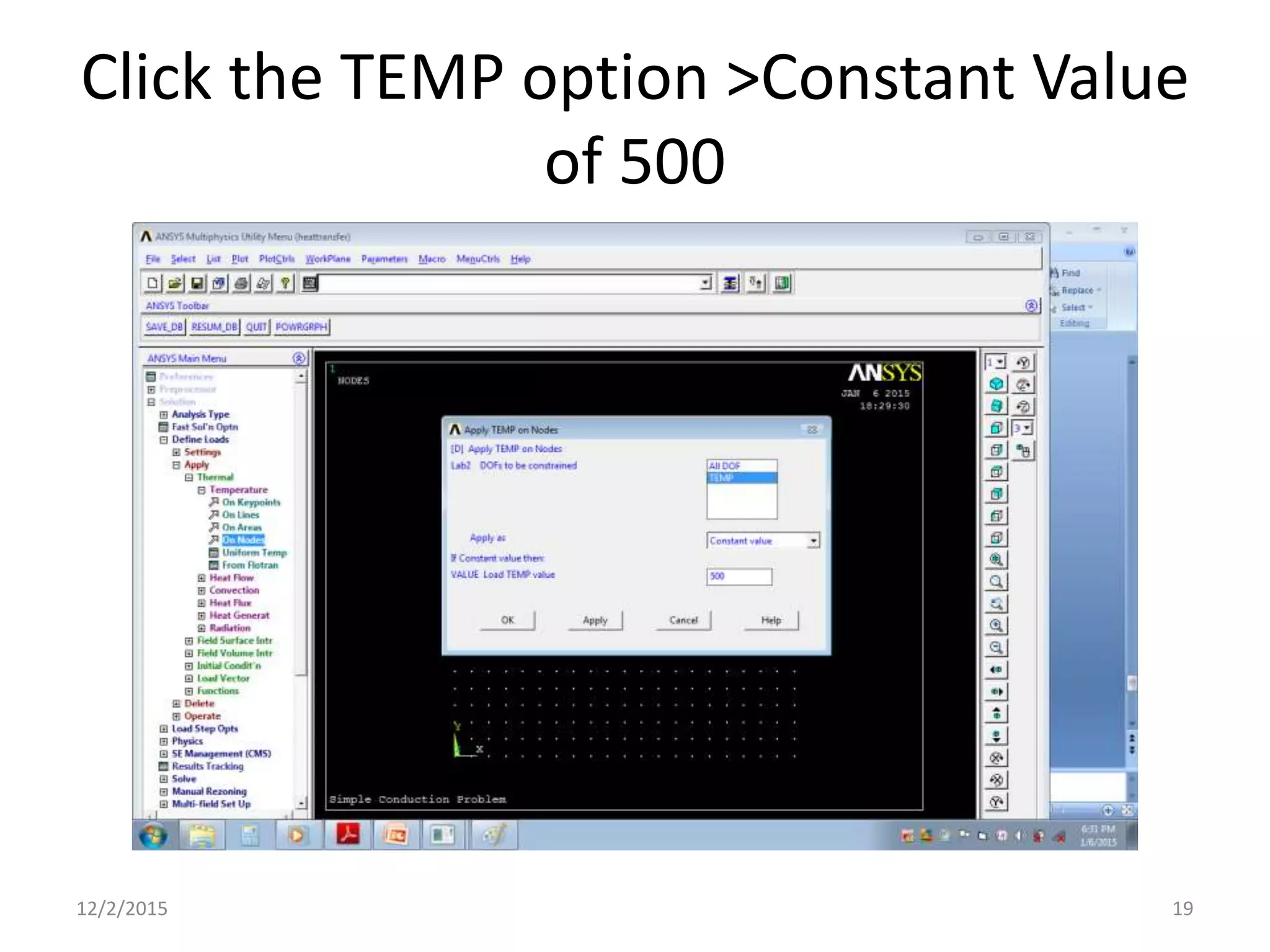
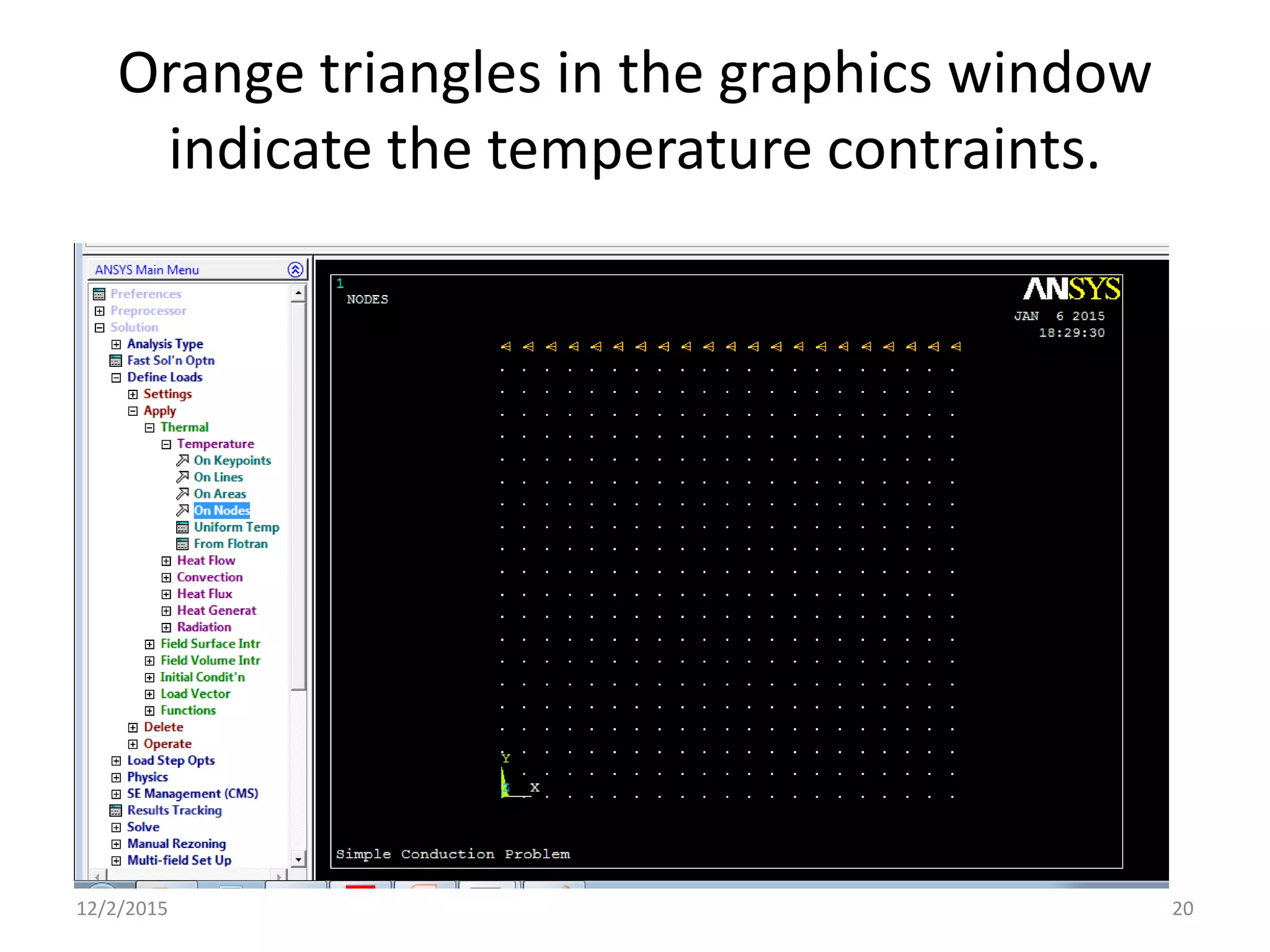
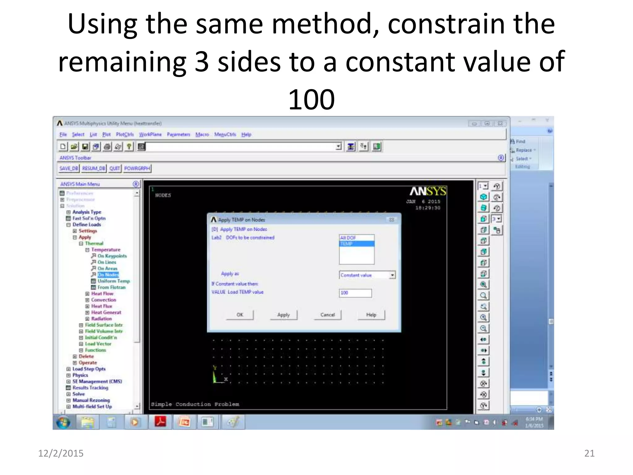
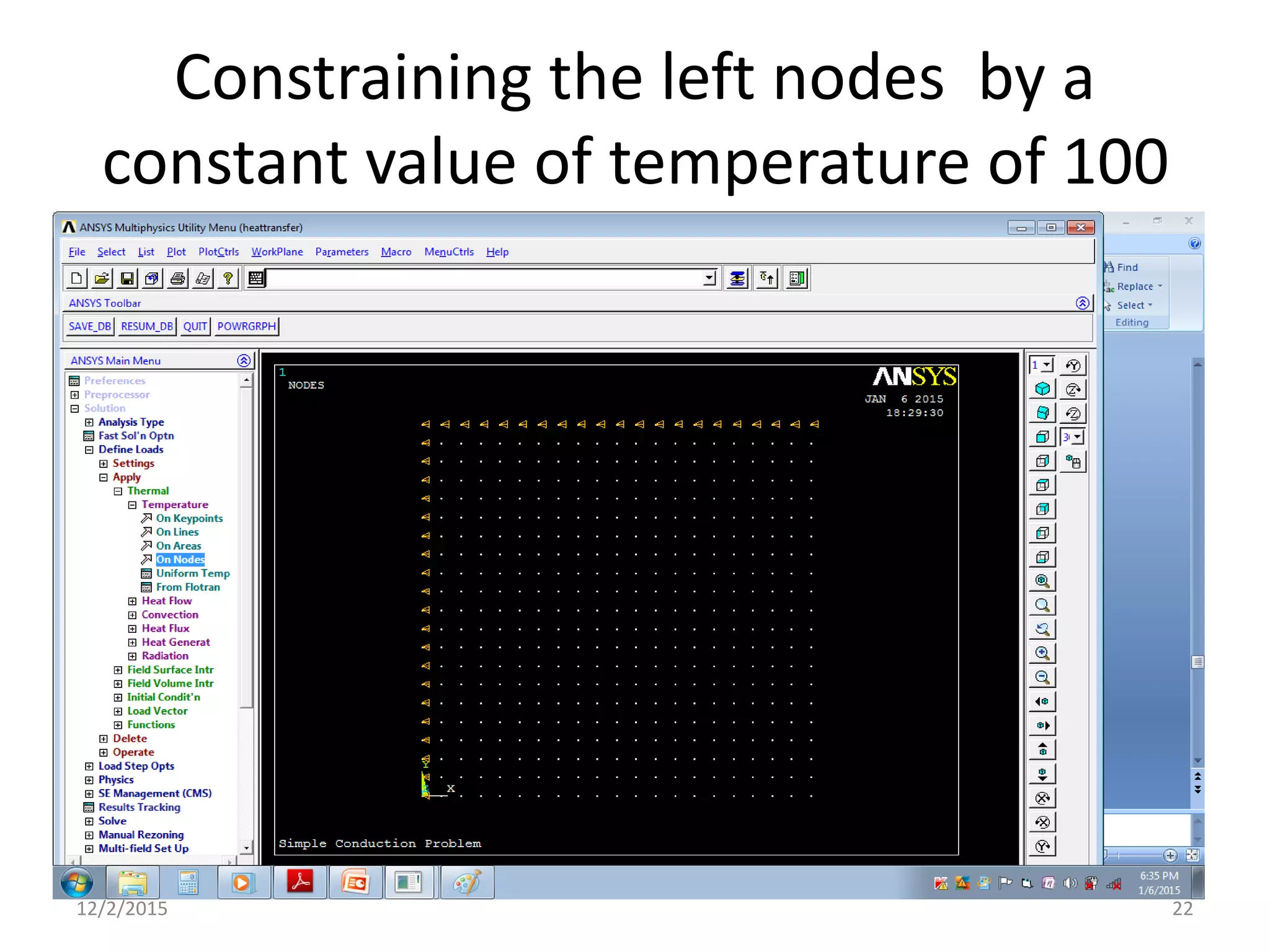
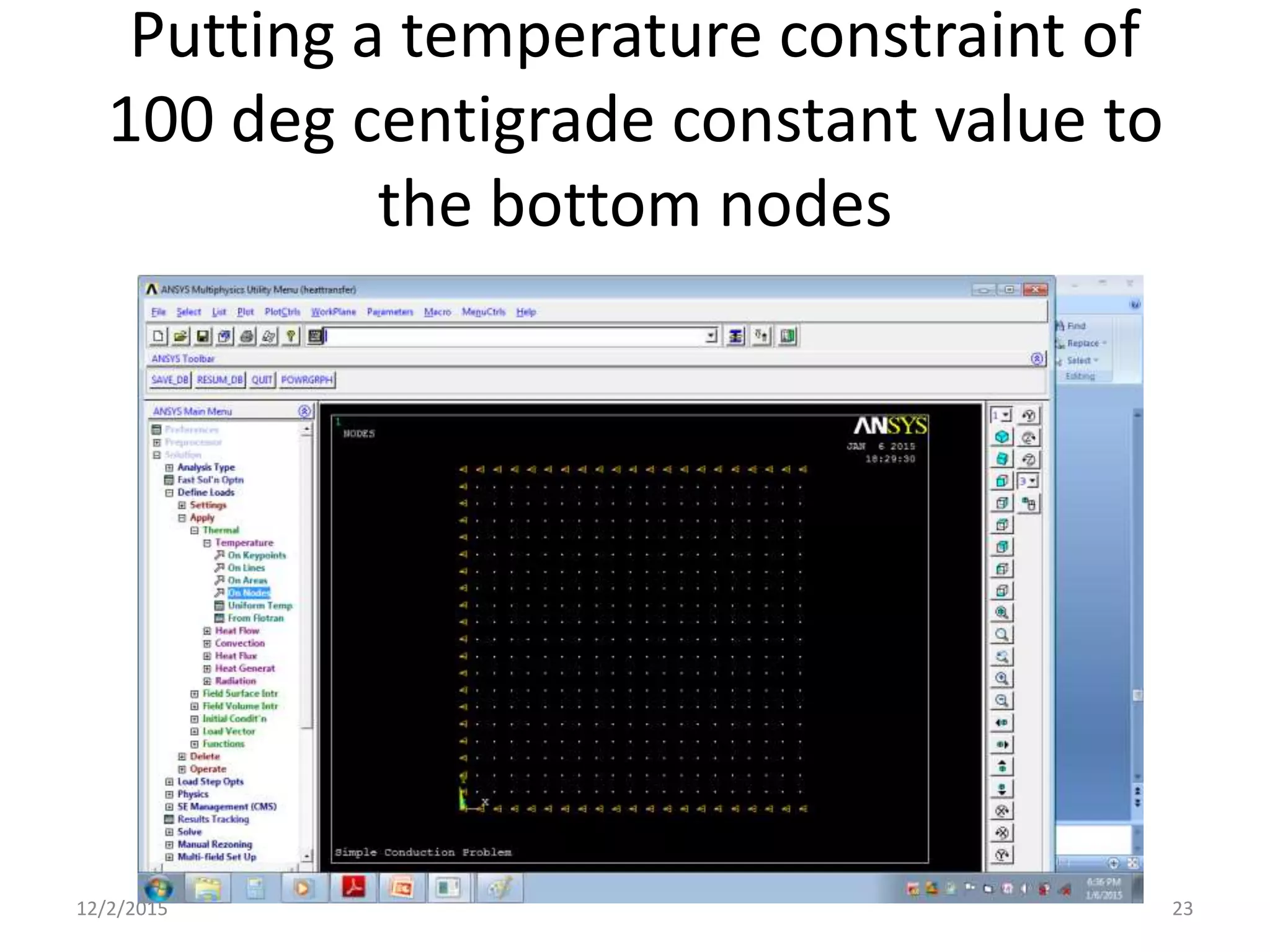
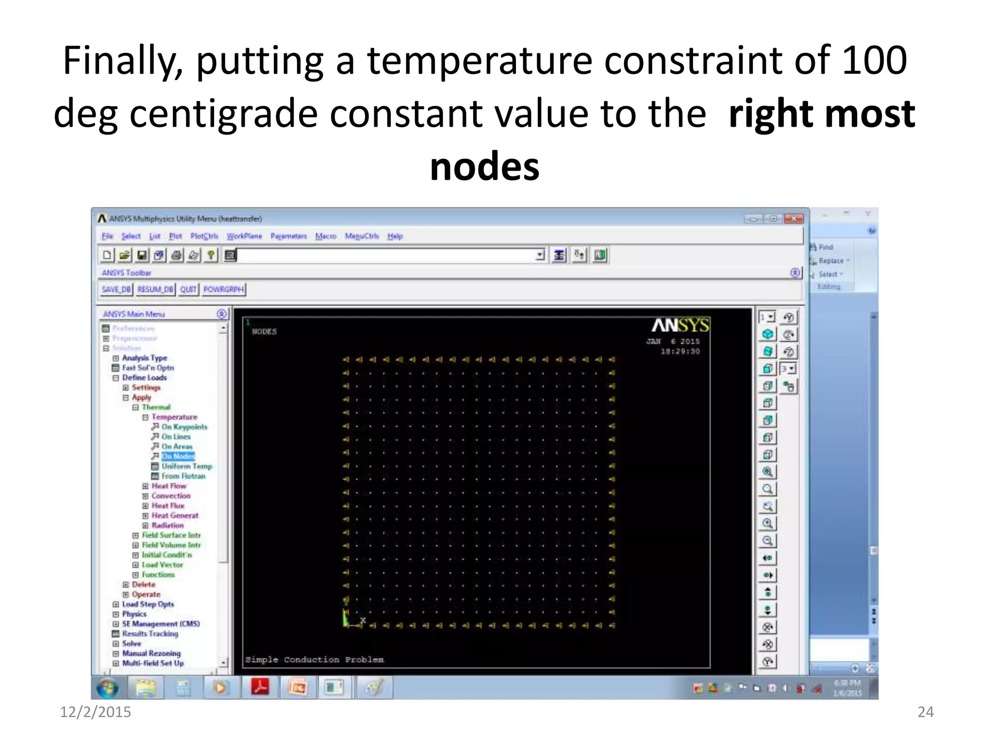
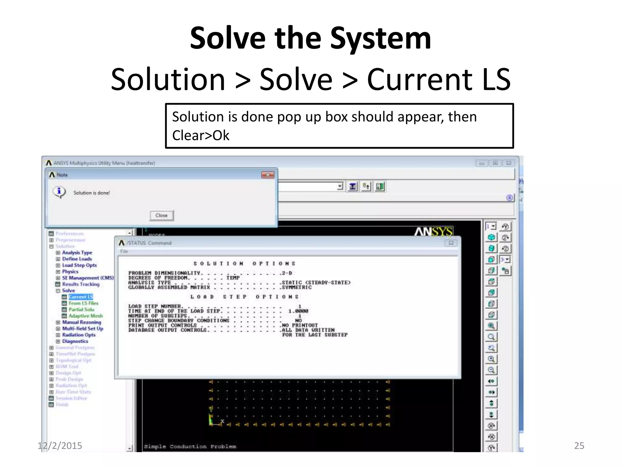
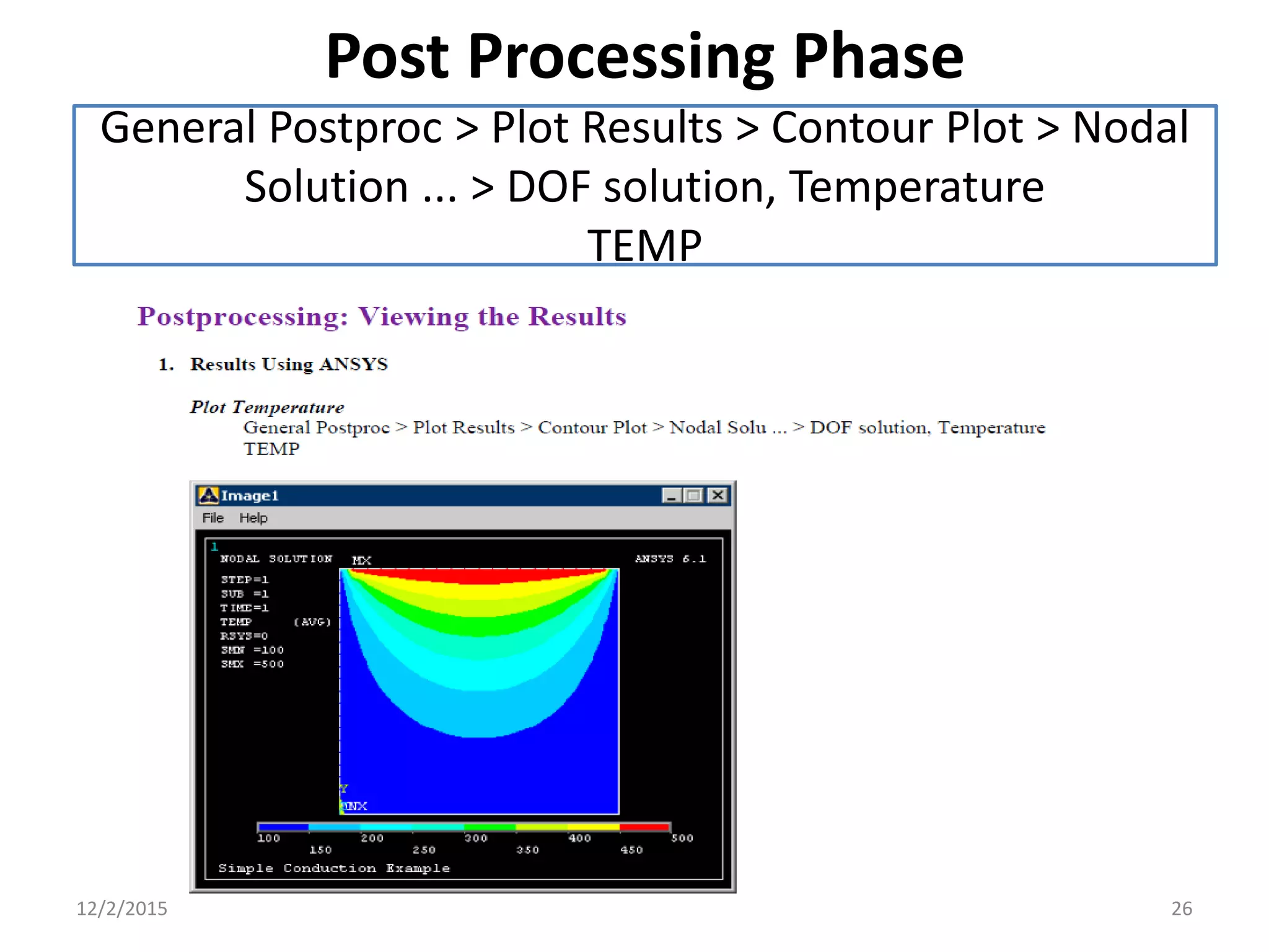
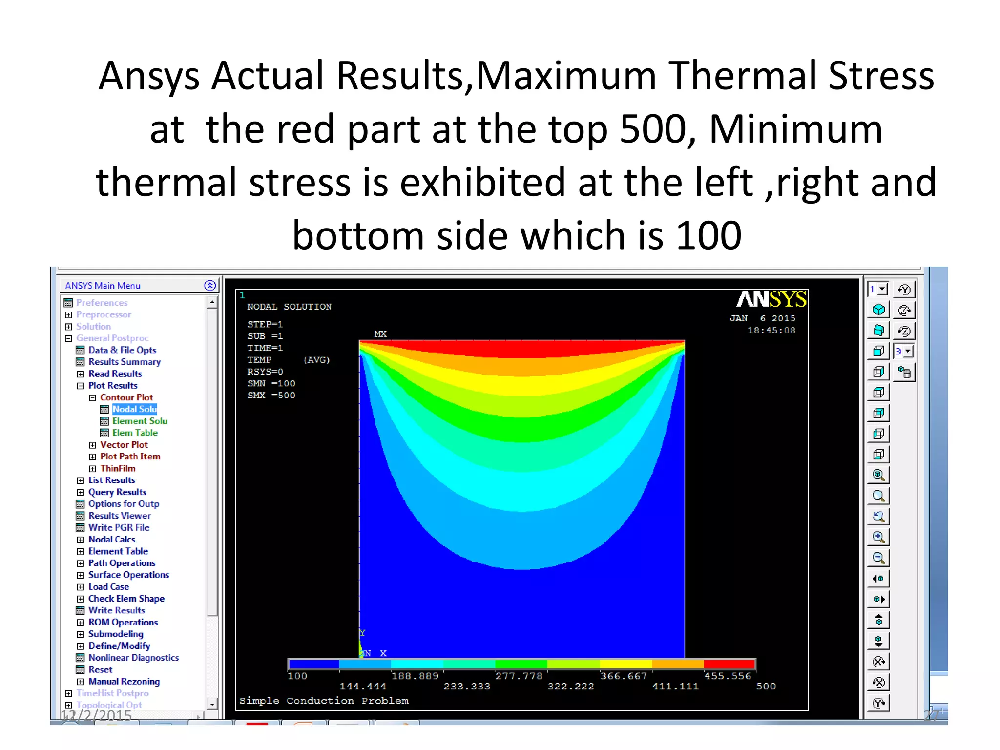
Simple Conduction
Prof Charlton S. Inao
Defence University
College of Engineering
Ansys LAB Heat transfer
PE -3011
12/2/2015 1
12/2/2015 2
Preprocessing
12/2/2015 3
File>Change Jobname> “Heat Transfer”;
File >change Title>”Simple Conduction
Problem”>Ok;Plot>Replot
12/2/2015 4
Preference>Thermal
12/2/2015 5
Preprocessing>Modeling>Create>Areas>Rectangle > By
two Corners>Wp x=0,WP y=0, width=1, height=1
12/2/2015 6
Preprocessor > Element Type > Add/Edit/Delete... > click 'Add' >
Select Thermal Solid, Quad
4Node 55
Define the type element
For this example, we will use PLANE55 (Thermal Solid, Quad 4node 55). This
element has 4 nodes and
a single DOF (temperature) at each node. PLANE55 can only be used for 2
dimensional steady-state or
transient thermal analysis
12/2/2015 7
Element Material Properties
Preprocessor > Material Props > Material Models > Thermal > Conductivity > Isotropic
> KXX =
10 (Thermal conductivity)
MP,KXX,1,10
12/2/2015 8
Mesh Size
Preprocessor > Meshing > Size Cntrls > ManualSize > Areas > All
Areas > 0.05
12/2/2015 9
Mesh
Preprocessor > Meshing > Mesh > Areas > Free >
Pick All
12/2/2015 10
Meshed area should look like this
12/2/2015 11
Solution Phase:
Assigning Loads
and Solving
12/2/2015 12
Define Analysis Type
Solution > Analysis Type > New Analysis >
Steady-State
12/2/2015 13
Apply Constraints
For thermal problems, constraints can be in the form of
Temperature, Heat Flow, Convection, Heat Flux,
Heat Generation, or Radiation.
In this example, all 4 sides of the block have fixed
temperatures.
 Solution > Define Loads > Apply
Note that all of the -Structural- options cannot be selected.
This is due to the type of element
(PLANE55) selected.
 Thermal > Temperature > On Nodes
 Click the Box option (shown below) and draw a box
around the nodes on the top line.
12/2/2015 14
12/2/2015 15
Reference Illustration
12/2/2015 16
Click the Box Option> Make a box to
enclose all the nodes at the top most
line as shown in the illustration below.
12/2/2015 17
Plot >Nodes ( select all the top nodes
by enclosing in the box)
12/2/2015 18
Click the TEMP option >Constant Value
of 500
12/2/2015 19
Orange triangles in the graphics window
indicate the temperature contraints.
12/2/2015 20
Using the same method, constrain the
remaining 3 sides to a constant value of
100
12/2/2015 21
Constraining the left nodes by a
constant value of temperature of 100
12/2/2015 22
Putting a temperature constraint of
100 deg centigrade constant value to
the bottom nodes
12/2/2015 23
Finally, putting a temperature constraint of 100
deg centigrade constant value to the right most
nodes
12/2/2015 24
Solve the System
Solution > Solve > Current LS
Solution is done pop up box should appear, then
Clear>Ok
12/2/2015 25
Post Processing Phase
General Postproc > Plot Results > Contour Plot > Nodal
Solution ... > DOF solution, Temperature
TEMP
12/2/2015 26
Ansys Actual Results,Maximum Thermal Stress
at the red part at the top 500, Minimum
thermal stress is exhibited at the left ,right and
bottom side which is 100
12/2/2015 27
Note
Note that due to the manner in which the boundary
contitions were applied, the top corners are held at a
temperature of 100. Recall that the nodes on the top of
the plate were constrained first, followed by the
side and bottom constraints. The top corner nodes were
therefore first constrained at 500C, then
'overwritten' when the side constraints were applied.
Decreasing the mesh size can minimize this effect,
however, one must be aware of the limitations in the
results at the corners.
12/2/2015 28
End of Presentation
Thank You Very Much
12/2/2015 29

Ansys lab simple conduction

  • 1.
    Simple Conduction Prof CharltonS. Inao Defence University College of Engineering Ansys LAB Heat transfer PE -3011 12/2/2015 1
  • 2.
  • 3.
  • 4.
    File>Change Jobname> “HeatTransfer”; File >change Title>”Simple Conduction Problem”>Ok;Plot>Replot 12/2/2015 4
  • 5.
  • 6.
    Preprocessing>Modeling>Create>Areas>Rectangle > By twoCorners>Wp x=0,WP y=0, width=1, height=1 12/2/2015 6
  • 7.
    Preprocessor > ElementType > Add/Edit/Delete... > click 'Add' > Select Thermal Solid, Quad 4Node 55 Define the type element For this example, we will use PLANE55 (Thermal Solid, Quad 4node 55). This element has 4 nodes and a single DOF (temperature) at each node. PLANE55 can only be used for 2 dimensional steady-state or transient thermal analysis 12/2/2015 7
  • 8.
    Element Material Properties Preprocessor> Material Props > Material Models > Thermal > Conductivity > Isotropic > KXX = 10 (Thermal conductivity) MP,KXX,1,10 12/2/2015 8
  • 9.
    Mesh Size Preprocessor >Meshing > Size Cntrls > ManualSize > Areas > All Areas > 0.05 12/2/2015 9
  • 10.
    Mesh Preprocessor > Meshing> Mesh > Areas > Free > Pick All 12/2/2015 10
  • 11.
    Meshed area shouldlook like this 12/2/2015 11
  • 12.
  • 13.
    Define Analysis Type Solution> Analysis Type > New Analysis > Steady-State 12/2/2015 13
  • 14.
    Apply Constraints For thermalproblems, constraints can be in the form of Temperature, Heat Flow, Convection, Heat Flux, Heat Generation, or Radiation. In this example, all 4 sides of the block have fixed temperatures.  Solution > Define Loads > Apply Note that all of the -Structural- options cannot be selected. This is due to the type of element (PLANE55) selected.  Thermal > Temperature > On Nodes  Click the Box option (shown below) and draw a box around the nodes on the top line. 12/2/2015 14
  • 15.
  • 16.
  • 17.
    Click the BoxOption> Make a box to enclose all the nodes at the top most line as shown in the illustration below. 12/2/2015 17
  • 18.
    Plot >Nodes (select all the top nodes by enclosing in the box) 12/2/2015 18
  • 19.
    Click the TEMPoption >Constant Value of 500 12/2/2015 19
  • 20.
    Orange triangles inthe graphics window indicate the temperature contraints. 12/2/2015 20
  • 21.
    Using the samemethod, constrain the remaining 3 sides to a constant value of 100 12/2/2015 21
  • 22.
    Constraining the leftnodes by a constant value of temperature of 100 12/2/2015 22
  • 23.
    Putting a temperatureconstraint of 100 deg centigrade constant value to the bottom nodes 12/2/2015 23
  • 24.
    Finally, putting atemperature constraint of 100 deg centigrade constant value to the right most nodes 12/2/2015 24
  • 25.
    Solve the System Solution> Solve > Current LS Solution is done pop up box should appear, then Clear>Ok 12/2/2015 25
  • 26.
    Post Processing Phase GeneralPostproc > Plot Results > Contour Plot > Nodal Solution ... > DOF solution, Temperature TEMP 12/2/2015 26
  • 27.
    Ansys Actual Results,MaximumThermal Stress at the red part at the top 500, Minimum thermal stress is exhibited at the left ,right and bottom side which is 100 12/2/2015 27
  • 28.
    Note Note that dueto the manner in which the boundary contitions were applied, the top corners are held at a temperature of 100. Recall that the nodes on the top of the plate were constrained first, followed by the side and bottom constraints. The top corner nodes were therefore first constrained at 500C, then 'overwritten' when the side constraints were applied. Decreasing the mesh size can minimize this effect, however, one must be aware of the limitations in the results at the corners. 12/2/2015 28
  • 29.
    End of Presentation ThankYou Very Much 12/2/2015 29