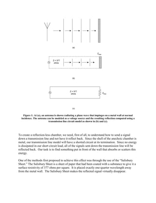
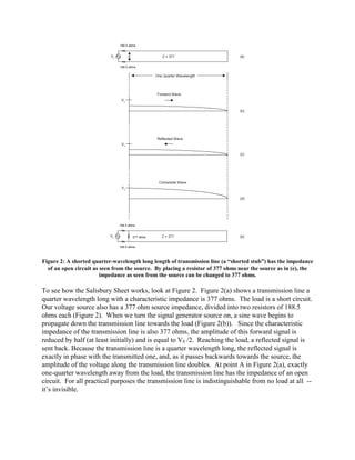
SlideShare a Scribd company logo
1 of 9
Download to read offline
How RF Anechoic Chambers Work
                    By Glen Dash, Ampyx LLC, GlenDash at alum.mit.edu
                             Copyright 1999, 2005 Ampyx LLC


A radio frequency “anechoic chamber” is a shielded room whose walls have been covered with a
material that scatters or absorbs so much of the incident energy that it can simulate free space. Its
origins can be traced to efforts to build aircraft which absorbed or scattered radar signals during
the Second World War. Recent innovations such as the use of ferrite tiles, have greatly enhanced
performance of these chambers.

Anechoic chambers may seem to operate through a bit of black magic, but the analysis of how
they work is really quite straightforward. Assume for a moment that an electromagnetic plane
wave (free space impedance = 377 ohms) strikes a wall at normal incidence. This can be modeled
as a signal passing down a transmission line with a 377 ohm characteristic impedance as shown
in Figure 1.
Figure 1: At (a), an antenna is shown radiating a plane wave that impinges on a metal wall at normal
  incidence. The antenna can be modeled as a voltage source and the resulting reflection computed using a
                            transmission line circuit model as shown in (b) and (c).


To create a reflection-less chamber, we need, first of all, to understand how to send a signal
down a transmission line and not have it reflect back. Since the shell of the anechoic chamber is
metal, our transmission line model will have a shorted circuit at its termination. Since no energy
is dissipated in our short circuit load, all of the signals sent down the transmission line will be
reflected back. Our task is to find something put in front of the wall that absorbs or scatters this
energy.

One of the methods first proposed to achieve this effect was through the use of the “Salisbury
Sheet.” The Salisbury Sheet is a sheet of paper that had been coated with a substance to give it a
surface resistivity of 377 ohms per square. It is placed exactly one-quarter wavelength away
from the metal wall. The Salisbury Sheet makes the reflected signal virtually disappear.
Figure 2: A shorted quarter-wavelength long length of transmission line (a “shorted stub”) has the impedance
  of an open circuit as seen from the source. By placing a resistor of 377 ohms near the source as in (e), the
                        impedance as seen from the source can be changed to 377 ohms.

To see how the Salisbury Sheet works, look at Figure 2. Figure 2(a) shows a transmission line a
quarter wavelength long with a characteristic impedance is 377 ohms. The load is a short circuit.
Our voltage source also has a 377 ohm source impedance, divided into two resistors of 188.5
ohms each (Figure 2). When we turn the signal generator source on, a sine wave begins to
propagate down the transmission line towards the load (Figure 2(b)). Since the characteristic
impedance of the transmission line is also 377 ohms, the amplitude of this forward signal is
reduced by half (at least initially) and is equal to V0 /2. Reaching the load, a reflected signal is
sent back. Because the transmission line is a quarter wavelength long, the reflected signal is
exactly in phase with the transmitted one, and, as it passes backwards towards the source, the
amplitude of the voltage along the transmission line doubles. At point A in Figure 2(a), exactly
one-quarter wavelength away from the load, the transmission line has the impedance of an open
circuit. For all practical purposes the transmission line is indistinguishable from no load at all --
it’s invisible.
Figure 3: The Salisbury Sheet provides anechoic effects at one frequency. Placing a resistive sheet with an
impedance of 377 ohms per square one quarter wavelength away from the wall results in impedance as seen
                                       from the source of 377 ohms.
Figure 4: The use of several sheets of resistive paper widens the bandwidth of absorbent effects.


As elegant a solution as a Salisbury Sheet is, its limitations are obvious. It only works at one
frequency. In order to make the Salisbury Sheet work over a larger range of frequencies, several
sheets can be used as shown in Figure 4. Here sheets of different surface resistivities are placed
at one-quarter wavelength intervals from the metal wall. The transmission line equivalent of
such an arrangement is also shown. The arrangement reduces the reflection coefficient from 1 to
less than .1 (equal to a reduction of reflected signal strength of greater than 20 dB), and it works
over a 2.5 to 1 bandwidth centered on λ.

Another approach is known as the “Jaumann Sandwich.” Here both the resistances and the
distances from the metal wall are tapered (Figure 5(a)). Reportedly, the Jaumann Sandwich can
achieve a 20 dB reduction in reflection over a 5 to 1 bandwidth (Reference 3).
Figure 5: The Jaumann Sandwich uses a staggered array of resistive sheets and reportedly achieves a 20 dB
reduction in reflected signal over a 5:1 bandwidth. For the case of normal incidence it can be modeled using
   the transmission line model in (b). Pyramidal absorbers use much the same effect to reduce reflection.


A modern implementation of theses tapered techniques employs pyramidal absorbers (Figure
5(c)). The tapered shape of the pyramidal material performs a role similar to the tapered
resistances of the Jaumann Sandwich. Many small reflections are created as the electromagnetic
wave passes into the pyramid and these reflections tend to cancel out. To be effective, however,
the pyramids must be at least one half wavelength long at the lowest frequency of interest. The
size of the pyramid needed to achieve this effect is mitigated somewhat by the fact that the
wavelength of the radio frequency signal as it passes through the pyramidal material is shorter
than the free space. It is reduced by a factor of:


                                               λr = 1 / ε r
Where:

         λr = Wavelength in media (that is, within the absorber)
εr = Permittivity relative to free space

Because of their size, providing for anechoic effects below 100 MHz requires the use of
technologies other than pyramidal absorbers. In the last 20 years, ferrite tiles have become
widely used as an absorbing mechanism. The key here is for the ferrite tile to present an
impedance approximately equal to 377 ohms. This is accomplished by making sure the ratio of
the permeability to the permittivity is equal to that of free space:

                                              µ
                                     Z=
                                              ε
                                                     µ0
                                     Z free space=      = 377 ohms
                                                     ε0
                                                     µr
                                     Z in media =
                                                     εr

That, in turn, is achieved by keeping the ratio of µr to εr equal to 377 ohms.

By itself that won’t prevent reflections however. What makes ferrite tiles work is that both the
permeability and the permittivity are complex, so that the material is lossy. A typical ferrite
material might have these properties:

                                          µ r = ε r = 60(2 - j1)


This results in a characteristic impedance of:

                                                      µr
                                        Z = 377            = 377 Ω
                                                      εr


The complex permeability and permittivity results in loss as the wave passes through the ferrite
tile. This loss is (Ref. 4):


                                            Loss = e-αd
                              d = thickness of the material in meters
                                       α = Re jωµσ - ω 2 µε
                                  2π                     2π                120π
                      α = Re[j(      ) µ r ε r ] = Re[j(    )60(2 - j1)] =
                                   λ                      λ                  λ
The conductivity of the ferrite tile can be considered to be zero. At 100 MHz, the loss for a one-
centimeter ferrite tile would be:

                                                120 π
                             Loss = e-αd = e-     λ
                                                      (.01)
                                                              = e-1.26 = .28 = 11dB


Therefore, as the wave passes through the ferrite tile, it is attenuated by 11 dB. As is reflects off
the metal surface behind the tile, the wave is attenuated another 11 dB, for a total of 22 db of
loss. Ferrite tiles will retain this absorbent effect at all frequencies for which the permeability
and the permittivity retain these values.
References

1. Ramo, Whinnery & Van Duzer, Field and Waves In Communications Electronic, John Wiley
& Sons, 1965.

2. Holloway, DeLyser, German, McKenna & Kanda, “Comparison of Electromagnetic Absorber
Used In Anechoic and Semi-Anechoic Chambers For Emissions and Immunity Testing of Digital
Devices,” IEEE Transactions on Electromagnetic Compatibility, February, 1997.

3. Kraus, Electromagnetics, Fourth Edition, McGraw-Hill, 1992.

More Related Content

What's hot

Power Penalty in Optical Communication
Power Penalty in Optical CommunicationPower Penalty in Optical Communication
Power Penalty in Optical CommunicationSanket Thakare
 
Application of dc generator at railway coach
Application of dc generator at railway coachApplication of dc generator at railway coach
Application of dc generator at railway coachjjasdxjz
 
Multiplexing and Multiple access
Multiplexing and Multiple accessMultiplexing and Multiple access
Multiplexing and Multiple accessDr. Ghanshyam Singh
 
LTE ADVANCED PPT
LTE ADVANCED PPTLTE ADVANCED PPT
LTE ADVANCED PPTTrinath
 
Self control of synchronous motor drives
Self control of synchronous motor drivesSelf control of synchronous motor drives
Self control of synchronous motor drivesvishalgohel12195
 
Chapter6 optical sources
Chapter6 optical sourcesChapter6 optical sources
Chapter6 optical sourcesvijju005
 
Optical fiber communication || History and working principle || Yaman Shrestha
Optical fiber communication || History and working principle || Yaman ShresthaOptical fiber communication || History and working principle || Yaman Shrestha
Optical fiber communication || History and working principle || Yaman ShresthaYaman Shrestha
 
Rise Time Budget Analysis and Design of Components
Rise Time Budget Analysis and Design of ComponentsRise Time Budget Analysis and Design of Components
Rise Time Budget Analysis and Design of ComponentsSaptarshi Mazumdar
 
speed control of three phase induction motor
speed control of three phase induction motorspeed control of three phase induction motor
speed control of three phase induction motorAshvani Shukla
 
Multiplexing and Multiple Access
Multiplexing and Multiple AccessMultiplexing and Multiple Access
Multiplexing and Multiple AccessRidwanul Hoque
 
Serial vs Parallel communication & Synchronous and Asynchronous transmission
Serial vs Parallel communication & Synchronous and Asynchronous transmissionSerial vs Parallel communication & Synchronous and Asynchronous transmission
Serial vs Parallel communication & Synchronous and Asynchronous transmissionRohanMistry15
 

What's hot (20)

Array antennas
Array antennasArray antennas
Array antennas
 
Power Penalty in Optical Communication
Power Penalty in Optical CommunicationPower Penalty in Optical Communication
Power Penalty in Optical Communication
 
Pll ppt
Pll pptPll ppt
Pll ppt
 
Basics of Patch antenna
Basics of Patch antennaBasics of Patch antenna
Basics of Patch antenna
 
Frequency translation
Frequency translationFrequency translation
Frequency translation
 
Application of dc generator at railway coach
Application of dc generator at railway coachApplication of dc generator at railway coach
Application of dc generator at railway coach
 
Multiplexing and Multiple access
Multiplexing and Multiple accessMultiplexing and Multiple access
Multiplexing and Multiple access
 
LTE ADVANCED PPT
LTE ADVANCED PPTLTE ADVANCED PPT
LTE ADVANCED PPT
 
Self control of synchronous motor drives
Self control of synchronous motor drivesSelf control of synchronous motor drives
Self control of synchronous motor drives
 
Chapter6 optical sources
Chapter6 optical sourcesChapter6 optical sources
Chapter6 optical sources
 
Chapter 5
Chapter 5Chapter 5
Chapter 5
 
Optical fiber communication || History and working principle || Yaman Shrestha
Optical fiber communication || History and working principle || Yaman ShresthaOptical fiber communication || History and working principle || Yaman Shrestha
Optical fiber communication || History and working principle || Yaman Shrestha
 
FUNDAMENTAL PARAMETERS OF ANTENNA
FUNDAMENTAL PARAMETERS OF ANTENNAFUNDAMENTAL PARAMETERS OF ANTENNA
FUNDAMENTAL PARAMETERS OF ANTENNA
 
Rise Time Budget Analysis and Design of Components
Rise Time Budget Analysis and Design of ComponentsRise Time Budget Analysis and Design of Components
Rise Time Budget Analysis and Design of Components
 
Microwave devices
Microwave devicesMicrowave devices
Microwave devices
 
speed control of three phase induction motor
speed control of three phase induction motorspeed control of three phase induction motor
speed control of three phase induction motor
 
Multiplexing and Multiple Access
Multiplexing and Multiple AccessMultiplexing and Multiple Access
Multiplexing and Multiple Access
 
Microwave cavity 1st 4
Microwave cavity 1st 4Microwave cavity 1st 4
Microwave cavity 1st 4
 
IGBT
IGBTIGBT
IGBT
 
Serial vs Parallel communication & Synchronous and Asynchronous transmission
Serial vs Parallel communication & Synchronous and Asynchronous transmissionSerial vs Parallel communication & Synchronous and Asynchronous transmission
Serial vs Parallel communication & Synchronous and Asynchronous transmission
 

Similar to Anechoic chambers how work

713_Transmission_Lines-F15.ppt
713_Transmission_Lines-F15.ppt713_Transmission_Lines-F15.ppt
713_Transmission_Lines-F15.pptDOAFCLF
 
713_Transmission_Lines-F21.ppt
713_Transmission_Lines-F21.ppt713_Transmission_Lines-F21.ppt
713_Transmission_Lines-F21.pptyash919530
 
713_Transmission_Lines-F21.ppt
713_Transmission_Lines-F21.ppt713_Transmission_Lines-F21.ppt
713_Transmission_Lines-F21.pptHalarMustafa1
 
713_Transmission_Lines-F21.ppt
713_Transmission_Lines-F21.ppt713_Transmission_Lines-F21.ppt
713_Transmission_Lines-F21.pptAnandKumar689627
 
SHIELDING & BONDING PPT.ppt
SHIELDING & BONDING PPT.pptSHIELDING & BONDING PPT.ppt
SHIELDING & BONDING PPT.ppthodeeeeee1
 
Geo-radar LOZA and it application for sounding high resistive sections in Sou...
Geo-radar LOZA and it application for sounding high resistive sections in Sou...Geo-radar LOZA and it application for sounding high resistive sections in Sou...
Geo-radar LOZA and it application for sounding high resistive sections in Sou...Leonid Krinitsky
 
Strip lines
Strip linesStrip lines
Strip linesrakeshkk
 
Electronic bands structure and gap in mid-infrared detector InAs/GaSb type II...
Electronic bands structure and gap in mid-infrared detector InAs/GaSb type II...Electronic bands structure and gap in mid-infrared detector InAs/GaSb type II...
Electronic bands structure and gap in mid-infrared detector InAs/GaSb type II...IJERA Editor
 
N 5-antenna fandamentals-f13
N 5-antenna fandamentals-f13N 5-antenna fandamentals-f13
N 5-antenna fandamentals-f1315010192
 
Plasmon-Polaritons And Their Use In Optical Sub-Wavelength. Event Of Copper A...
Plasmon-Polaritons And Their Use In Optical Sub-Wavelength. Event Of Copper A...Plasmon-Polaritons And Their Use In Optical Sub-Wavelength. Event Of Copper A...
Plasmon-Polaritons And Their Use In Optical Sub-Wavelength. Event Of Copper A...ijrap
 
Dual band antenna using reactive loading
Dual band antenna using reactive loadingDual band antenna using reactive loading
Dual band antenna using reactive loadingPrathamesh Bhat
 
Electromagnetic earthing and coupling, Electromagnetic Shielding
Electromagnetic earthing and coupling, Electromagnetic Shielding Electromagnetic earthing and coupling, Electromagnetic Shielding
Electromagnetic earthing and coupling, Electromagnetic Shielding Suleyman Demirel University
 
Electric field detector
Electric field detectorElectric field detector
Electric field detectorJawad Ali
 

Similar to Anechoic chambers how work (20)

713_Transmission_Lines-F15.ppt
713_Transmission_Lines-F15.ppt713_Transmission_Lines-F15.ppt
713_Transmission_Lines-F15.ppt
 
713_Transmission_Lines-F21.ppt
713_Transmission_Lines-F21.ppt713_Transmission_Lines-F21.ppt
713_Transmission_Lines-F21.ppt
 
713_Transmission_Lines-F21.ppt
713_Transmission_Lines-F21.ppt713_Transmission_Lines-F21.ppt
713_Transmission_Lines-F21.ppt
 
713_Transmission_Lines-F21.ppt
713_Transmission_Lines-F21.ppt713_Transmission_Lines-F21.ppt
713_Transmission_Lines-F21.ppt
 
SHIELDING & BONDING PPT.ppt
SHIELDING & BONDING PPT.pptSHIELDING & BONDING PPT.ppt
SHIELDING & BONDING PPT.ppt
 
Geo-radar LOZA and it application for sounding high resistive sections in Sou...
Geo-radar LOZA and it application for sounding high resistive sections in Sou...Geo-radar LOZA and it application for sounding high resistive sections in Sou...
Geo-radar LOZA and it application for sounding high resistive sections in Sou...
 
Strip lines
Strip linesStrip lines
Strip lines
 
Electronic bands structure and gap in mid-infrared detector InAs/GaSb type II...
Electronic bands structure and gap in mid-infrared detector InAs/GaSb type II...Electronic bands structure and gap in mid-infrared detector InAs/GaSb type II...
Electronic bands structure and gap in mid-infrared detector InAs/GaSb type II...
 
N 5-antenna fandamentals-f13
N 5-antenna fandamentals-f13N 5-antenna fandamentals-f13
N 5-antenna fandamentals-f13
 
Microstrip antennas
Microstrip antennasMicrostrip antennas
Microstrip antennas
 
Plasmon-Polaritons And Their Use In Optical Sub-Wavelength. Event Of Copper A...
Plasmon-Polaritons And Their Use In Optical Sub-Wavelength. Event Of Copper A...Plasmon-Polaritons And Their Use In Optical Sub-Wavelength. Event Of Copper A...
Plasmon-Polaritons And Their Use In Optical Sub-Wavelength. Event Of Copper A...
 
Plasmon-Polaritons And Their Use In Optical Sub-Wavelength. Event Of Copper A...
Plasmon-Polaritons And Their Use In Optical Sub-Wavelength. Event Of Copper A...Plasmon-Polaritons And Their Use In Optical Sub-Wavelength. Event Of Copper A...
Plasmon-Polaritons And Their Use In Optical Sub-Wavelength. Event Of Copper A...
 
Dual band antenna using reactive loading
Dual band antenna using reactive loadingDual band antenna using reactive loading
Dual band antenna using reactive loading
 
3 p8 1518
3 p8 15183 p8 1518
3 p8 1518
 
Electromagnetic earthing and coupling, Electromagnetic Shielding
Electromagnetic earthing and coupling, Electromagnetic Shielding Electromagnetic earthing and coupling, Electromagnetic Shielding
Electromagnetic earthing and coupling, Electromagnetic Shielding
 
MOLT_Salahun
MOLT_SalahunMOLT_Salahun
MOLT_Salahun
 
f2001_landinger.ppt
f2001_landinger.pptf2001_landinger.ppt
f2001_landinger.ppt
 
Falling magnet
Falling magnetFalling magnet
Falling magnet
 
Electric field detector
Electric field detectorElectric field detector
Electric field detector
 

Recently uploaded

Capitol Tech U Doctoral Presentation - April 2024.pptx
Capitol Tech U Doctoral Presentation - April 2024.pptxCapitol Tech U Doctoral Presentation - April 2024.pptx
Capitol Tech U Doctoral Presentation - April 2024.pptxCapitolTechU
 
call girls in Kamla Market (DELHI) 🔝 >༒9953330565🔝 genuine Escort Service 🔝✔️✔️
call girls in Kamla Market (DELHI) 🔝 >༒9953330565🔝 genuine Escort Service 🔝✔️✔️call girls in Kamla Market (DELHI) 🔝 >༒9953330565🔝 genuine Escort Service 🔝✔️✔️
call girls in Kamla Market (DELHI) 🔝 >༒9953330565🔝 genuine Escort Service 🔝✔️✔️9953056974 Low Rate Call Girls In Saket, Delhi NCR
 
History Class XII Ch. 3 Kinship, Caste and Class (1).pptx
History Class XII Ch. 3 Kinship, Caste and Class (1).pptxHistory Class XII Ch. 3 Kinship, Caste and Class (1).pptx
History Class XII Ch. 3 Kinship, Caste and Class (1).pptxsocialsciencegdgrohi
 
Solving Puzzles Benefits Everyone (English).pptx
Solving Puzzles Benefits Everyone (English).pptxSolving Puzzles Benefits Everyone (English).pptx
Solving Puzzles Benefits Everyone (English).pptxOH TEIK BIN
 
Incoming and Outgoing Shipments in 1 STEP Using Odoo 17
Incoming and Outgoing Shipments in 1 STEP Using Odoo 17Incoming and Outgoing Shipments in 1 STEP Using Odoo 17
Incoming and Outgoing Shipments in 1 STEP Using Odoo 17Celine George
 
Types of Journalistic Writing Grade 8.pptx
Types of Journalistic Writing Grade 8.pptxTypes of Journalistic Writing Grade 8.pptx
Types of Journalistic Writing Grade 8.pptxEyham Joco
 
Introduction to ArtificiaI Intelligence in Higher Education
Introduction to ArtificiaI Intelligence in Higher EducationIntroduction to ArtificiaI Intelligence in Higher Education
Introduction to ArtificiaI Intelligence in Higher Educationpboyjonauth
 
MARGINALIZATION (Different learners in Marginalized Group
MARGINALIZATION (Different learners in Marginalized GroupMARGINALIZATION (Different learners in Marginalized Group
MARGINALIZATION (Different learners in Marginalized GroupJonathanParaisoCruz
 
Full Stack Web Development Course for Beginners
Full Stack Web Development Course  for BeginnersFull Stack Web Development Course  for Beginners
Full Stack Web Development Course for BeginnersSabitha Banu
 
Hierarchy of management that covers different levels of management
Hierarchy of management that covers different levels of managementHierarchy of management that covers different levels of management
Hierarchy of management that covers different levels of managementmkooblal
 
Enzyme, Pharmaceutical Aids, Miscellaneous Last Part of Chapter no 5th.pdf
Enzyme, Pharmaceutical Aids, Miscellaneous Last Part of Chapter no 5th.pdfEnzyme, Pharmaceutical Aids, Miscellaneous Last Part of Chapter no 5th.pdf
Enzyme, Pharmaceutical Aids, Miscellaneous Last Part of Chapter no 5th.pdfSumit Tiwari
 
Framing an Appropriate Research Question 6b9b26d93da94caf993c038d9efcdedb.pdf
Framing an Appropriate Research Question 6b9b26d93da94caf993c038d9efcdedb.pdfFraming an Appropriate Research Question 6b9b26d93da94caf993c038d9efcdedb.pdf
Framing an Appropriate Research Question 6b9b26d93da94caf993c038d9efcdedb.pdfUjwalaBharambe
 
DATA STRUCTURE AND ALGORITHM for beginners
DATA STRUCTURE AND ALGORITHM for beginnersDATA STRUCTURE AND ALGORITHM for beginners
DATA STRUCTURE AND ALGORITHM for beginnersSabitha Banu
 
Historical philosophical, theoretical, and legal foundations of special and i...
Historical philosophical, theoretical, and legal foundations of special and i...Historical philosophical, theoretical, and legal foundations of special and i...
Historical philosophical, theoretical, and legal foundations of special and i...jaredbarbolino94
 
Presiding Officer Training module 2024 lok sabha elections
Presiding Officer Training module 2024 lok sabha electionsPresiding Officer Training module 2024 lok sabha elections
Presiding Officer Training module 2024 lok sabha electionsanshu789521
 
Employee wellbeing at the workplace.pptx
Employee wellbeing at the workplace.pptxEmployee wellbeing at the workplace.pptx
Employee wellbeing at the workplace.pptxNirmalaLoungPoorunde1
 
Meghan Sutherland In Media Res Media Component
Meghan Sutherland In Media Res Media ComponentMeghan Sutherland In Media Res Media Component
Meghan Sutherland In Media Res Media ComponentInMediaRes1
 

Recently uploaded (20)

Capitol Tech U Doctoral Presentation - April 2024.pptx
Capitol Tech U Doctoral Presentation - April 2024.pptxCapitol Tech U Doctoral Presentation - April 2024.pptx
Capitol Tech U Doctoral Presentation - April 2024.pptx
 
call girls in Kamla Market (DELHI) 🔝 >༒9953330565🔝 genuine Escort Service 🔝✔️✔️
call girls in Kamla Market (DELHI) 🔝 >༒9953330565🔝 genuine Escort Service 🔝✔️✔️call girls in Kamla Market (DELHI) 🔝 >༒9953330565🔝 genuine Escort Service 🔝✔️✔️
call girls in Kamla Market (DELHI) 🔝 >༒9953330565🔝 genuine Escort Service 🔝✔️✔️
 
History Class XII Ch. 3 Kinship, Caste and Class (1).pptx
History Class XII Ch. 3 Kinship, Caste and Class (1).pptxHistory Class XII Ch. 3 Kinship, Caste and Class (1).pptx
History Class XII Ch. 3 Kinship, Caste and Class (1).pptx
 
Model Call Girl in Bikash Puri Delhi reach out to us at 🔝9953056974🔝
Model Call Girl in Bikash Puri  Delhi reach out to us at 🔝9953056974🔝Model Call Girl in Bikash Puri  Delhi reach out to us at 🔝9953056974🔝
Model Call Girl in Bikash Puri Delhi reach out to us at 🔝9953056974🔝
 
Solving Puzzles Benefits Everyone (English).pptx
Solving Puzzles Benefits Everyone (English).pptxSolving Puzzles Benefits Everyone (English).pptx
Solving Puzzles Benefits Everyone (English).pptx
 
Incoming and Outgoing Shipments in 1 STEP Using Odoo 17
Incoming and Outgoing Shipments in 1 STEP Using Odoo 17Incoming and Outgoing Shipments in 1 STEP Using Odoo 17
Incoming and Outgoing Shipments in 1 STEP Using Odoo 17
 
9953330565 Low Rate Call Girls In Rohini Delhi NCR
9953330565 Low Rate Call Girls In Rohini  Delhi NCR9953330565 Low Rate Call Girls In Rohini  Delhi NCR
9953330565 Low Rate Call Girls In Rohini Delhi NCR
 
Types of Journalistic Writing Grade 8.pptx
Types of Journalistic Writing Grade 8.pptxTypes of Journalistic Writing Grade 8.pptx
Types of Journalistic Writing Grade 8.pptx
 
OS-operating systems- ch04 (Threads) ...
OS-operating systems- ch04 (Threads) ...OS-operating systems- ch04 (Threads) ...
OS-operating systems- ch04 (Threads) ...
 
Introduction to ArtificiaI Intelligence in Higher Education
Introduction to ArtificiaI Intelligence in Higher EducationIntroduction to ArtificiaI Intelligence in Higher Education
Introduction to ArtificiaI Intelligence in Higher Education
 
MARGINALIZATION (Different learners in Marginalized Group
MARGINALIZATION (Different learners in Marginalized GroupMARGINALIZATION (Different learners in Marginalized Group
MARGINALIZATION (Different learners in Marginalized Group
 
Full Stack Web Development Course for Beginners
Full Stack Web Development Course  for BeginnersFull Stack Web Development Course  for Beginners
Full Stack Web Development Course for Beginners
 
Hierarchy of management that covers different levels of management
Hierarchy of management that covers different levels of managementHierarchy of management that covers different levels of management
Hierarchy of management that covers different levels of management
 
Enzyme, Pharmaceutical Aids, Miscellaneous Last Part of Chapter no 5th.pdf
Enzyme, Pharmaceutical Aids, Miscellaneous Last Part of Chapter no 5th.pdfEnzyme, Pharmaceutical Aids, Miscellaneous Last Part of Chapter no 5th.pdf
Enzyme, Pharmaceutical Aids, Miscellaneous Last Part of Chapter no 5th.pdf
 
Framing an Appropriate Research Question 6b9b26d93da94caf993c038d9efcdedb.pdf
Framing an Appropriate Research Question 6b9b26d93da94caf993c038d9efcdedb.pdfFraming an Appropriate Research Question 6b9b26d93da94caf993c038d9efcdedb.pdf
Framing an Appropriate Research Question 6b9b26d93da94caf993c038d9efcdedb.pdf
 
DATA STRUCTURE AND ALGORITHM for beginners
DATA STRUCTURE AND ALGORITHM for beginnersDATA STRUCTURE AND ALGORITHM for beginners
DATA STRUCTURE AND ALGORITHM for beginners
 
Historical philosophical, theoretical, and legal foundations of special and i...
Historical philosophical, theoretical, and legal foundations of special and i...Historical philosophical, theoretical, and legal foundations of special and i...
Historical philosophical, theoretical, and legal foundations of special and i...
 
Presiding Officer Training module 2024 lok sabha elections
Presiding Officer Training module 2024 lok sabha electionsPresiding Officer Training module 2024 lok sabha elections
Presiding Officer Training module 2024 lok sabha elections
 
Employee wellbeing at the workplace.pptx
Employee wellbeing at the workplace.pptxEmployee wellbeing at the workplace.pptx
Employee wellbeing at the workplace.pptx
 
Meghan Sutherland In Media Res Media Component
Meghan Sutherland In Media Res Media ComponentMeghan Sutherland In Media Res Media Component
Meghan Sutherland In Media Res Media Component
 

Anechoic chambers how work

  • 1. How RF Anechoic Chambers Work By Glen Dash, Ampyx LLC, GlenDash at alum.mit.edu Copyright 1999, 2005 Ampyx LLC A radio frequency “anechoic chamber” is a shielded room whose walls have been covered with a material that scatters or absorbs so much of the incident energy that it can simulate free space. Its origins can be traced to efforts to build aircraft which absorbed or scattered radar signals during the Second World War. Recent innovations such as the use of ferrite tiles, have greatly enhanced performance of these chambers. Anechoic chambers may seem to operate through a bit of black magic, but the analysis of how they work is really quite straightforward. Assume for a moment that an electromagnetic plane wave (free space impedance = 377 ohms) strikes a wall at normal incidence. This can be modeled as a signal passing down a transmission line with a 377 ohm characteristic impedance as shown in Figure 1.
  • 2. Figure 1: At (a), an antenna is shown radiating a plane wave that impinges on a metal wall at normal incidence. The antenna can be modeled as a voltage source and the resulting reflection computed using a transmission line circuit model as shown in (b) and (c). To create a reflection-less chamber, we need, first of all, to understand how to send a signal down a transmission line and not have it reflect back. Since the shell of the anechoic chamber is metal, our transmission line model will have a shorted circuit at its termination. Since no energy is dissipated in our short circuit load, all of the signals sent down the transmission line will be reflected back. Our task is to find something put in front of the wall that absorbs or scatters this energy. One of the methods first proposed to achieve this effect was through the use of the “Salisbury Sheet.” The Salisbury Sheet is a sheet of paper that had been coated with a substance to give it a surface resistivity of 377 ohms per square. It is placed exactly one-quarter wavelength away from the metal wall. The Salisbury Sheet makes the reflected signal virtually disappear.
  • 3. Figure 2: A shorted quarter-wavelength long length of transmission line (a “shorted stub”) has the impedance of an open circuit as seen from the source. By placing a resistor of 377 ohms near the source as in (e), the impedance as seen from the source can be changed to 377 ohms. To see how the Salisbury Sheet works, look at Figure 2. Figure 2(a) shows a transmission line a quarter wavelength long with a characteristic impedance is 377 ohms. The load is a short circuit. Our voltage source also has a 377 ohm source impedance, divided into two resistors of 188.5 ohms each (Figure 2). When we turn the signal generator source on, a sine wave begins to propagate down the transmission line towards the load (Figure 2(b)). Since the characteristic impedance of the transmission line is also 377 ohms, the amplitude of this forward signal is reduced by half (at least initially) and is equal to V0 /2. Reaching the load, a reflected signal is sent back. Because the transmission line is a quarter wavelength long, the reflected signal is exactly in phase with the transmitted one, and, as it passes backwards towards the source, the amplitude of the voltage along the transmission line doubles. At point A in Figure 2(a), exactly one-quarter wavelength away from the load, the transmission line has the impedance of an open circuit. For all practical purposes the transmission line is indistinguishable from no load at all -- it’s invisible.
  • 4. Figure 3: The Salisbury Sheet provides anechoic effects at one frequency. Placing a resistive sheet with an impedance of 377 ohms per square one quarter wavelength away from the wall results in impedance as seen from the source of 377 ohms.
  • 5. Figure 4: The use of several sheets of resistive paper widens the bandwidth of absorbent effects. As elegant a solution as a Salisbury Sheet is, its limitations are obvious. It only works at one frequency. In order to make the Salisbury Sheet work over a larger range of frequencies, several sheets can be used as shown in Figure 4. Here sheets of different surface resistivities are placed at one-quarter wavelength intervals from the metal wall. The transmission line equivalent of such an arrangement is also shown. The arrangement reduces the reflection coefficient from 1 to less than .1 (equal to a reduction of reflected signal strength of greater than 20 dB), and it works over a 2.5 to 1 bandwidth centered on λ. Another approach is known as the “Jaumann Sandwich.” Here both the resistances and the distances from the metal wall are tapered (Figure 5(a)). Reportedly, the Jaumann Sandwich can achieve a 20 dB reduction in reflection over a 5 to 1 bandwidth (Reference 3).
  • 6. Figure 5: The Jaumann Sandwich uses a staggered array of resistive sheets and reportedly achieves a 20 dB reduction in reflected signal over a 5:1 bandwidth. For the case of normal incidence it can be modeled using the transmission line model in (b). Pyramidal absorbers use much the same effect to reduce reflection. A modern implementation of theses tapered techniques employs pyramidal absorbers (Figure 5(c)). The tapered shape of the pyramidal material performs a role similar to the tapered resistances of the Jaumann Sandwich. Many small reflections are created as the electromagnetic wave passes into the pyramid and these reflections tend to cancel out. To be effective, however, the pyramids must be at least one half wavelength long at the lowest frequency of interest. The size of the pyramid needed to achieve this effect is mitigated somewhat by the fact that the wavelength of the radio frequency signal as it passes through the pyramidal material is shorter than the free space. It is reduced by a factor of: λr = 1 / ε r Where: λr = Wavelength in media (that is, within the absorber)
  • 7. εr = Permittivity relative to free space Because of their size, providing for anechoic effects below 100 MHz requires the use of technologies other than pyramidal absorbers. In the last 20 years, ferrite tiles have become widely used as an absorbing mechanism. The key here is for the ferrite tile to present an impedance approximately equal to 377 ohms. This is accomplished by making sure the ratio of the permeability to the permittivity is equal to that of free space: µ Z= ε µ0 Z free space= = 377 ohms ε0 µr Z in media = εr That, in turn, is achieved by keeping the ratio of µr to εr equal to 377 ohms. By itself that won’t prevent reflections however. What makes ferrite tiles work is that both the permeability and the permittivity are complex, so that the material is lossy. A typical ferrite material might have these properties: µ r = ε r = 60(2 - j1) This results in a characteristic impedance of: µr Z = 377 = 377 Ω εr The complex permeability and permittivity results in loss as the wave passes through the ferrite tile. This loss is (Ref. 4): Loss = e-αd d = thickness of the material in meters α = Re jωµσ - ω 2 µε 2π 2π 120π α = Re[j( ) µ r ε r ] = Re[j( )60(2 - j1)] = λ λ λ
  • 8. The conductivity of the ferrite tile can be considered to be zero. At 100 MHz, the loss for a one- centimeter ferrite tile would be: 120 π Loss = e-αd = e- λ (.01) = e-1.26 = .28 = 11dB Therefore, as the wave passes through the ferrite tile, it is attenuated by 11 dB. As is reflects off the metal surface behind the tile, the wave is attenuated another 11 dB, for a total of 22 db of loss. Ferrite tiles will retain this absorbent effect at all frequencies for which the permeability and the permittivity retain these values.
  • 9. References 1. Ramo, Whinnery & Van Duzer, Field and Waves In Communications Electronic, John Wiley & Sons, 1965. 2. Holloway, DeLyser, German, McKenna & Kanda, “Comparison of Electromagnetic Absorber Used In Anechoic and Semi-Anechoic Chambers For Emissions and Immunity Testing of Digital Devices,” IEEE Transactions on Electromagnetic Compatibility, February, 1997. 3. Kraus, Electromagnetics, Fourth Edition, McGraw-Hill, 1992.