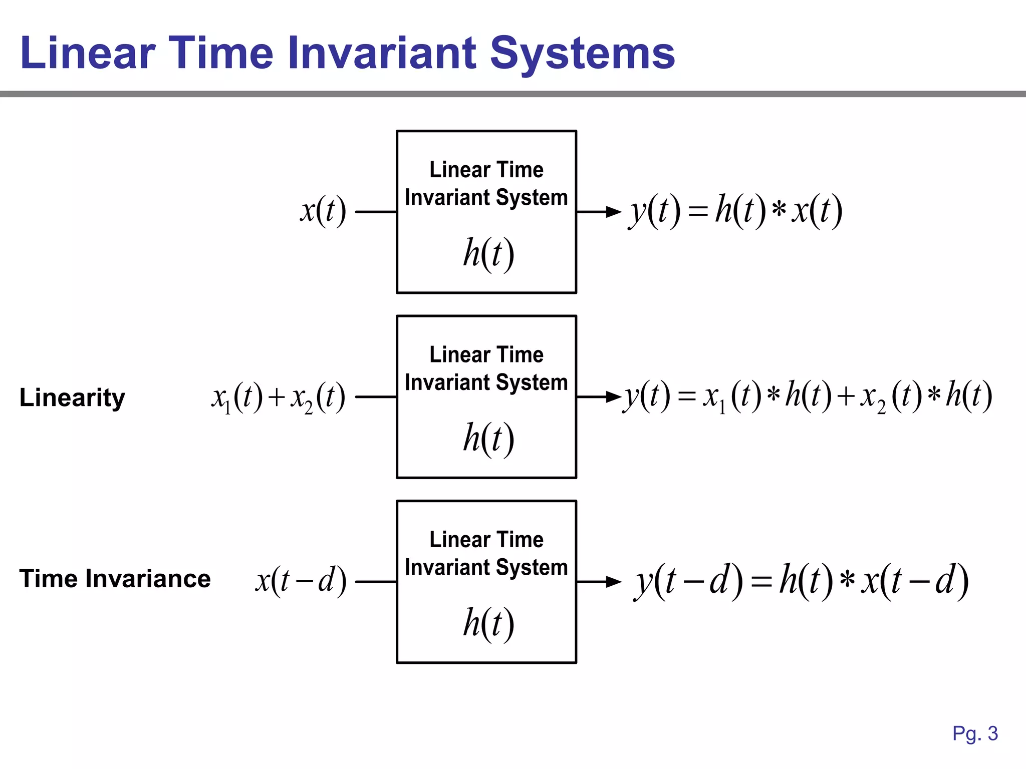
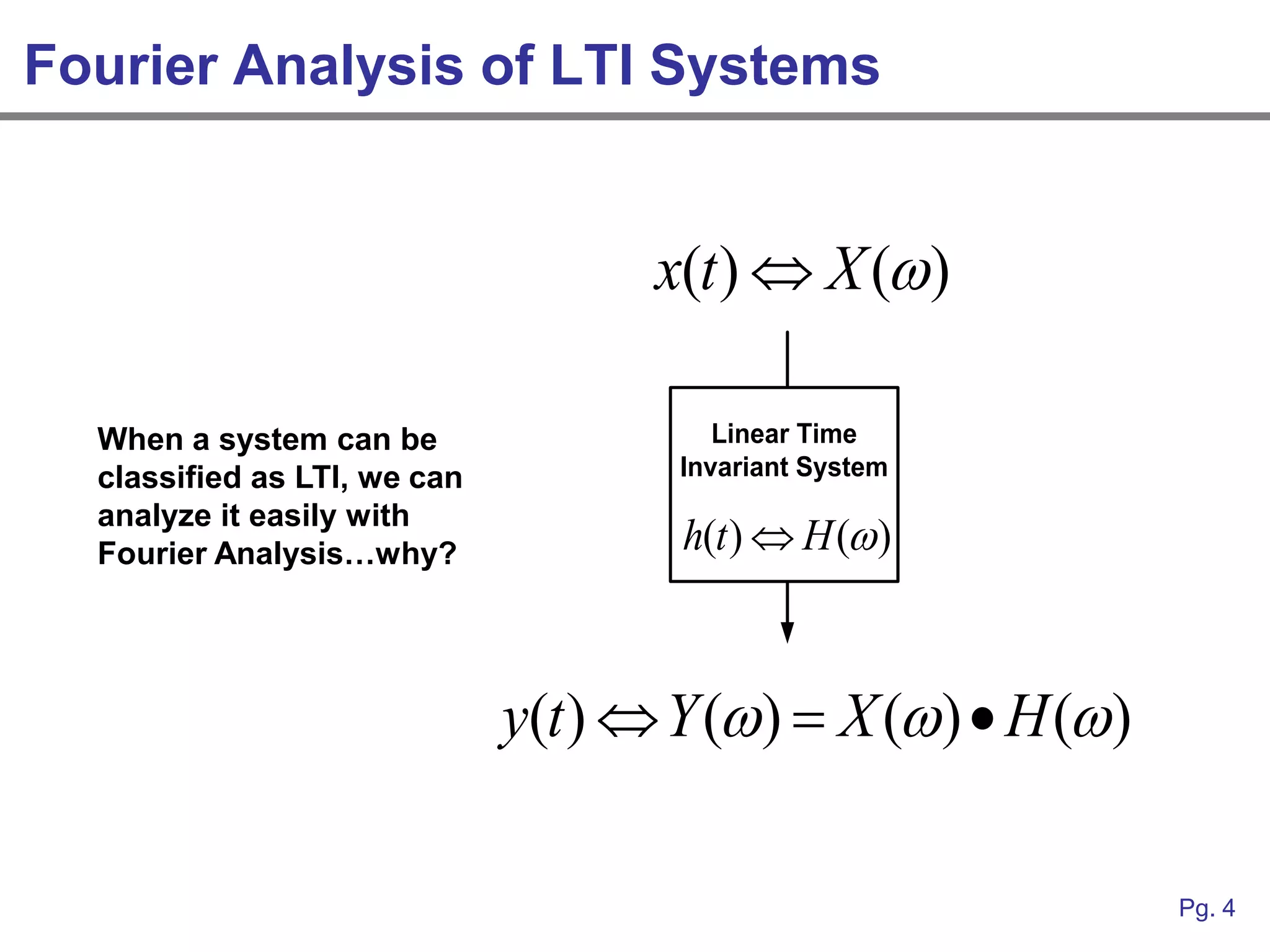
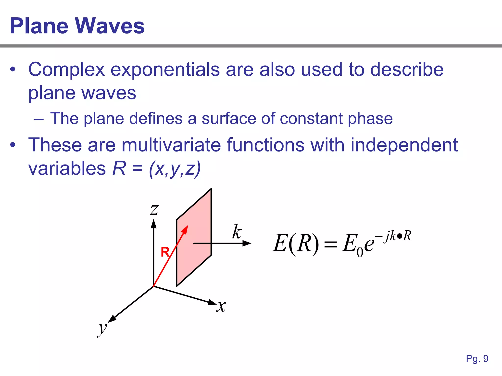
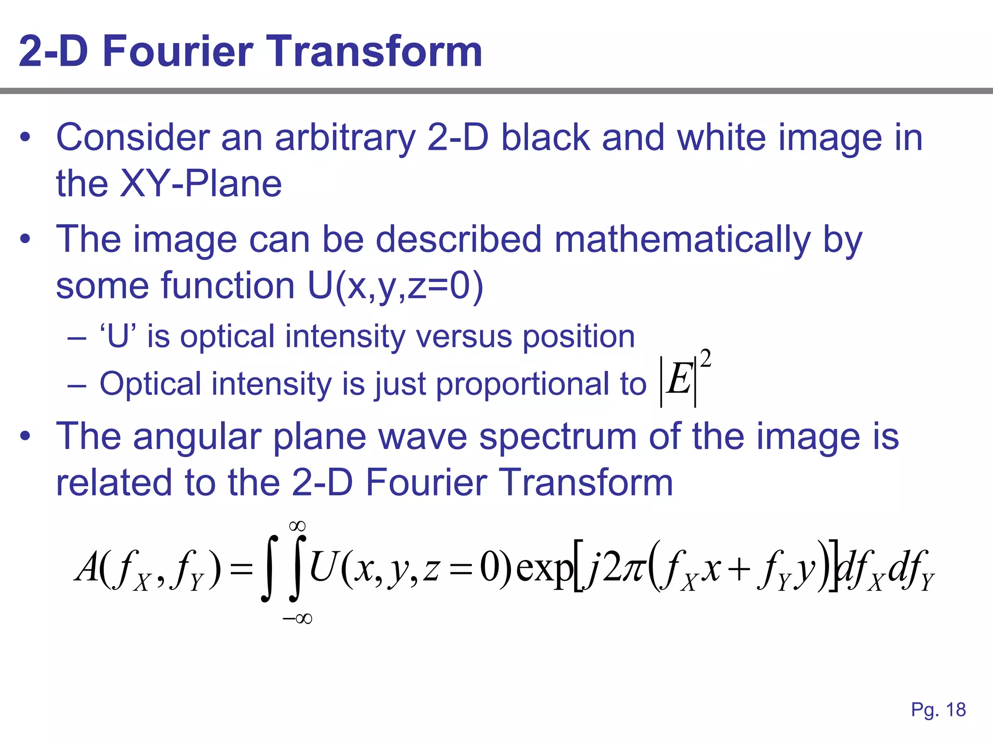
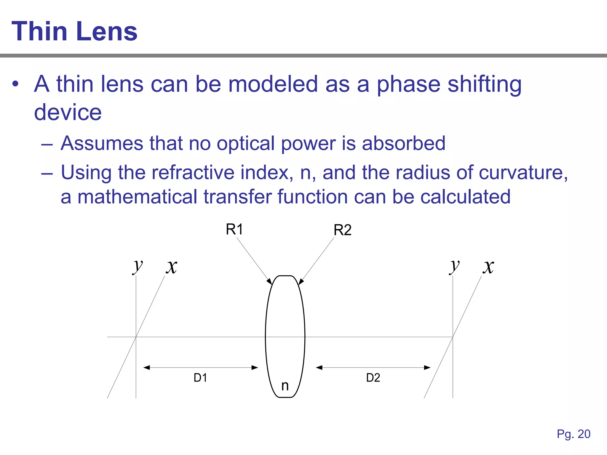
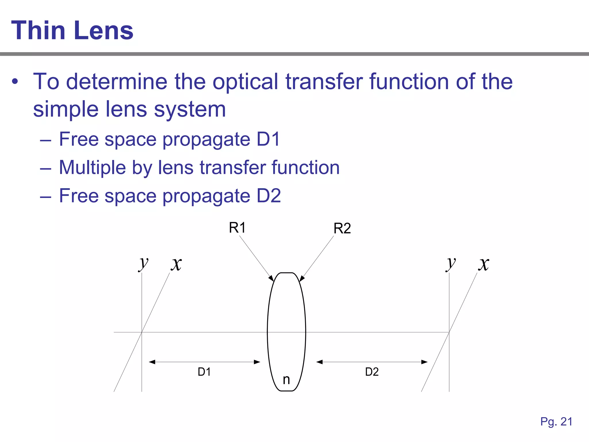
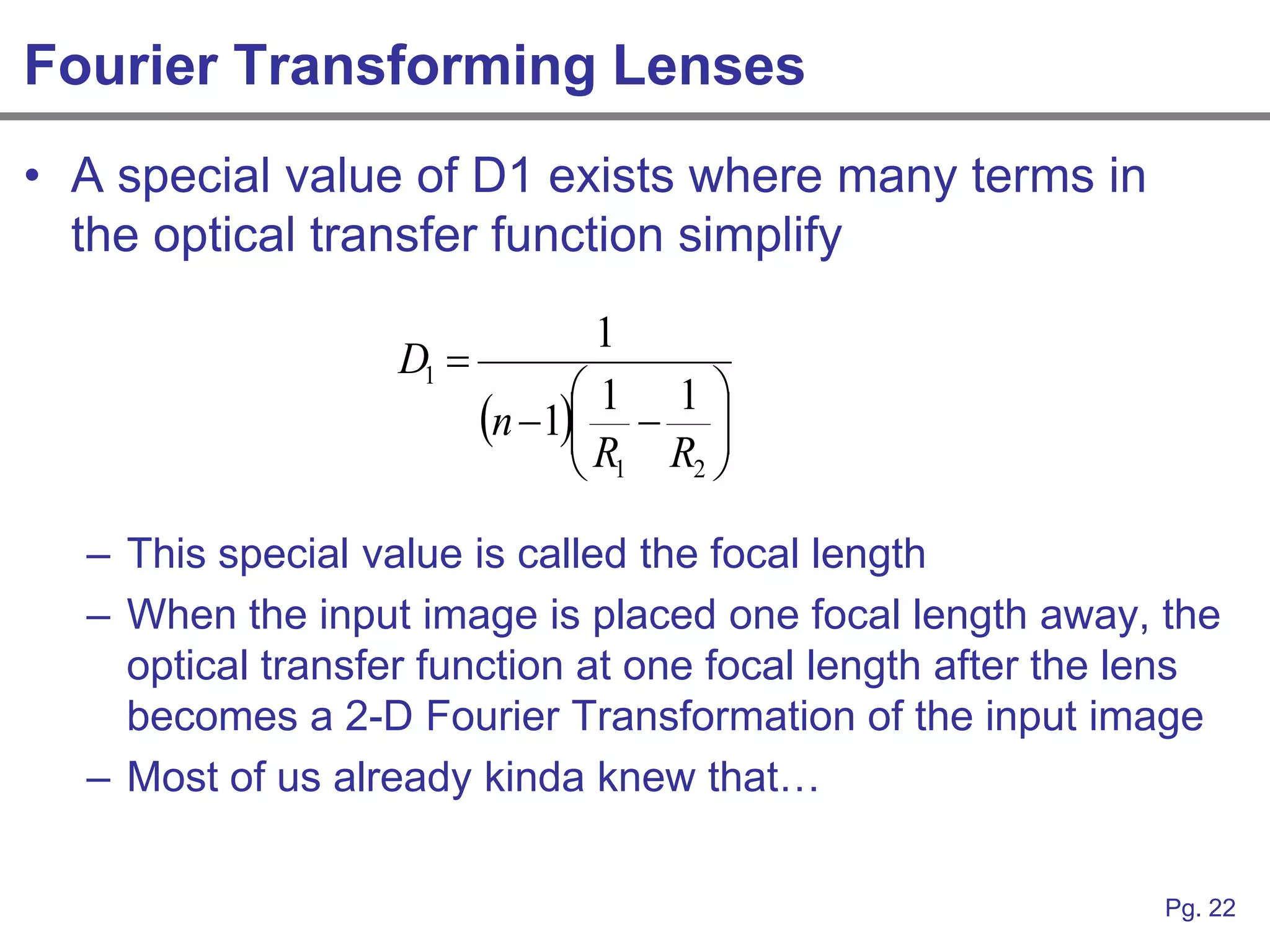
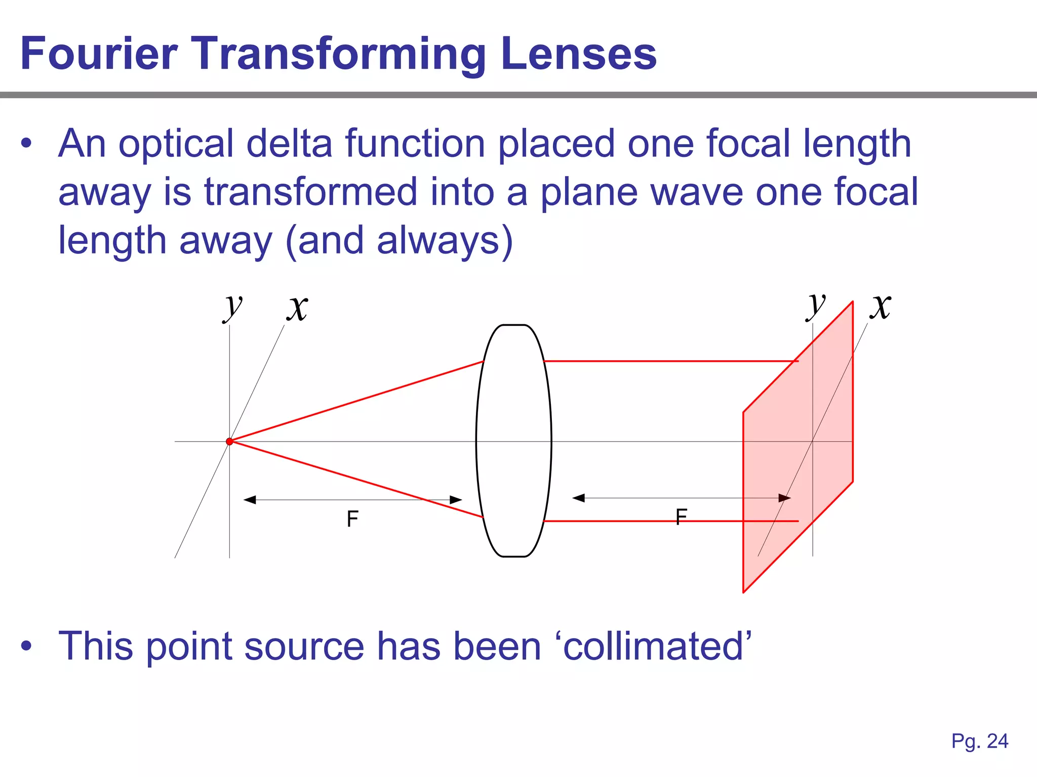
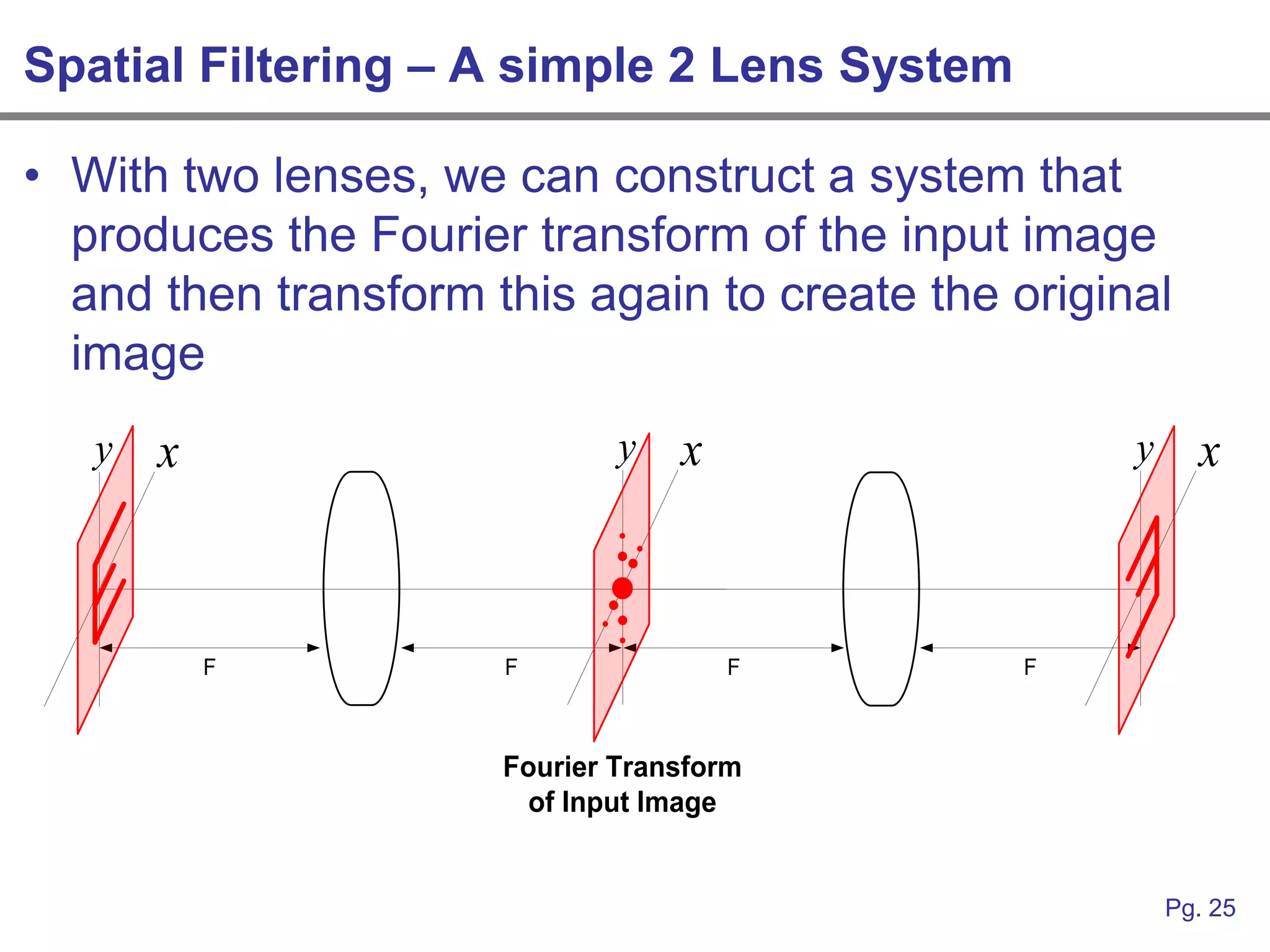
SlideShare a Scribd company logo
1 of 27
Download to read offline
Application of Linear Systems
Analysis to 2-D Optical Images
       (Fourier Optics)

        An Intuitive Approach

          Andrew Josephson
       ajosephson@comcast.net


                                 Pg. 1
Fourier Transforms of Electrical Signals
• As electrical engineers, we conceptualize the
  Fourier transformation and Fourier synthesis of
  voltages and currents frequently in circuit analysis
• Why do we use the Fourier Transform?
• There are other transforms
   –   Hilbert
   –   Hankel
   –   Abel
   –   Radon
• What makes the Fourier Transform special?


                                                         Pg. 2
Linear Time Invariant Systems

                                        Linear Time
                            x(t )    Invariant System
                                                        y(t )  h(t )  x(t )
                                          h(t )

                                        Linear Time
Linearity         x1(t )  x2 (t )   Invariant System
                                                        y(t )  x1 (t )  h(t )  x2 (t )  h(t )
                                          h(t )

                                        Linear Time
Time Invariance        x(t  d )     Invariant System
                                                         y(t  d )  h(t )  x(t  d )
                                          h(t )

                                                                                            Pg. 3
Fourier Analysis of LTI Systems


                                     x(t )  X ( )

  When a system can be                    Linear Time
  classified as LTI, we can            Invariant System

                                       h(t )  H ( )
  analyze it easily with
  Fourier Analysis…why?


                              y(t )  Y ( )  X ( )  H ( )

                                                                 Pg. 4
Eigen Function of LTI Systems
• The Eigen function of an LTI system is a
  mathematical function of time, that when applied as
  a system input, results in a system output of
  identical mathematical from
  – The output equals the input scaled by a constant „A‟
  – Delayed in time by „d‟


               Linear Time
    (t )   Invariant System
                               y(t )  h(t )  (t )  A  (t  d )
                 h(t )


                                                                       Pg. 5
Eigen Function of LTI Systems
• Complex exponentials are the Eigen functions of LTI
  systems

                    (t )  e    jt

• Complex exponentials are also the Kernel of the
  Fourier Integral

                      1    
             X ( )       
                                          jt
                                x(t )e           dt
                      2   


                                                      Pg. 6
Fourier Analysis of LTI Systems Revisited
• Conceptually, when we analyze
  an LTI system, we represent the
  input signal x(t) as a summation
                                          x(t )  c0  c1e j1t  c2e j2t  ...
  of linearly scaled Eigen functions
  (complex exponentials)
    – Fourier Decomposition
                                                     Linear Time
    – The signal‟s “spectrum”                     Invariant System
• We can then run each complex
  exponential through the system                        h(t )
  easily because they give rise to a
  linearly scaled output that is
  delayed in time

                                y(t )  K0c0  K1c1e j1 (t d )  K2c2e j2 (t d )  ...
• The output y(t) is the summation
  of these scaled and delayed
  complex exponentials

                                                                                        Pg. 7
Answer to the Million Dollar Question
• We use the Fourier Transform to analyze LTI
  systems because the Eigen function of an LTI
  system IS the Kernel of the Fourier Integral
• When we do not have an LTI system, we usually
  assume it is closely approximated by one, or force it
  to operate in a well-behaved region
  – Linearization
• The complex exponentials we deal with in circuits
  are single variable functions with independent
  variable „t‟
• Where else in electrical engineering do we use
  complex exponentials?

                                                      Pg. 8
Plane Waves
• Complex exponentials are also used to describe
  plane waves
  – The plane defines a surface of constant phase
• These are multivariate functions with independent
  variables R = (x,y,z)

                 z
                             k                 jkR
                     R           E(R)  E0e

                         x
          y
                                                       Pg. 9
Plane Waves as Eigen Functions
• Plane waves are Eigen functions of certain system
  types as well
  – Since the independent variable is no longer time, we
    aren‟t interested in Linear Time Invariant Systems
• We are now interested in the more general Linear
  Shift Invariant System
  – Shift refers to spatial movement since the independent
    variables now describe position instead of time


                                                             Pg. 10
Fourier Optics
• Fourier Optics is the application of linear shift
  invariant system theory to optical systems
• The plane wave in an optical system is represented
  by the multivariate complex exponential just like the
  sine wave in an LTI system is represented by the
                     jt
  single variable e
• Just like an electrical signal can be represented as
  summation of sine waves, an optical image can be
  represented as a summation of plane waves
  – Angular Plane Wave Spectrum


                                                     Pg. 11
Concept of Spatial Frequency
• Assume a plane wave propagates in z-direction
  (down the optical axis) y
                                                  jkz
                                 E( x, y, z)  E0e
                   k
                                  x
                  z        

• The image plane (x-y) is normal to the optical axis
• The projection of lines of constant phase onto the x-
  y plane is zero (spatial frequency equivalent to DC)

                                                         Pg. 12
Concept of Spatial Frequency
• Deflecting the wave-vector at an angle other than
  zero gives a projection of the plane wave intensity
  into the image plane (max and min)
                y


       k
                        x
        z       
• This example deflects k into the y-direction creating
  a nonzero spatial frequency in the y-direction

                                                        Pg. 13
Concept of Spatial Frequency
• Increasing the angle of deflection increases the
  spatial frequency of intensity maximum/minimum
                           y


            k
                               x
               z           
                       y
                   k


                               x
           z           
                                                     Pg. 14
Concept of Spatial Frequency


                               Pg. 15
Concept of Spatial Frequency
• Spatial frequency in the y-direction can be denoted
  as f y and has units 1/cm


           1
           fy


                                                    Pg. 16
Angular Plane Wave Spectrum
• An arbitrary 2-D field distribution (image) can be decomposed
  into a spectrum of plane waves
   – Assuming monochromatic light
• Just like the Fourier Transform of an electrical signal
  represents the magnitude and phase of each sinusoid in the
  signal spectrum, the 2-D Fourier Transform of an image
  represents the magnitude and phase of each plane wave in
  the image spectrum
• High spatial frequency -> plane wave at large angles
• Low spatial frequency -> plane wave at small angles


                                                           Pg. 17
2-D Fourier Transform
• Consider an arbitrary 2-D black and white image in
  the XY-Plane
• The image can be described mathematically by
  some function U(x,y,z=0)
  – „U‟ is optical intensity versus position
                                                       2
  – Optical intensity is just proportional to      E
• The angular plane wave spectrum of the image is
  related to the 2-D Fourier Transform
                    
   A( f X , fY )   U ( x, y, z  0) exp j 2  f X x  fY y df X dfY
                    


                                                                        Pg. 18
LSI Optical Systems
• In Linear Shift Invariant optical systems, we can use
  Fourier analysis to decompose an image into its
  spectrum, multiply the spectrum by the optical
  transfer function(s), and inverse transform to get the
  resulting output
   – Note: Free space propagation of optical images can be
     modeled as an LSI system
   – This technique correctly models diffraction
   – This technique produces identical results to the full
     Rayleigh-Sommerfeld solutions


                                                         Pg. 19
Thin Lens
• A thin lens can be modeled as a phase shifting
  device
  – Assumes that no optical power is absorbed
  – Using the refractive index, n, and the radius of curvature,
    a mathematical transfer function can be calculated
                         R1        R2

            y   x                                y   x


                    D1                  D2
                              n


                                                             Pg. 20
Thin Lens
• To determine the optical transfer function of the
  simple lens system
  – Free space propagate D1
  – Multiple by lens transfer function
  – Free space propagate D2
                          R1         R2

             y   x                             y   x


                     D1                   D2
                               n

                                                       Pg. 21
Fourier Transforming Lenses
• A special value of D1 exists where many terms in
  the optical transfer function simplify
                                 1
                   D1 
                                1 1
                          n 1  
                                R R 
                                 1 2


  – This special value is called the focal length
  – When the input image is placed one focal length away, the
    optical transfer function at one focal length after the lens
    becomes a 2-D Fourier Transformation of the input image
  – Most of us already kinda knew that…

                                                            Pg. 22
Fourier Transforming Lenses
• A delta function and sine wave (complex
  exponential) form a Fourier Transform pair
• What is the image equivalent of a delta function?
  – A point of light
• We know that a plane wave is a complex
  exponential
  – A point of light and a plane wave form a Fourier Transform
    Pair
• This is exactly what happens when we place a point
  of light one focal length away from a lens


                                                           Pg. 23
Fourier Transforming Lenses
• An optical delta function placed one focal length
  away is transformed into a plane wave one focal
  length away (and always)
            y x                               y x


                  F                  F


• This point source has been „collimated‟

                                                      Pg. 24
Spatial Filtering – A simple 2 Lens System

• With two lenses, we can construct a system that
  produces the Fourier transform of the input image
  and then transform this again to create the original
  image
   y   x                      y   x                 y     x


           F          F               F        F


                      Fourier Transform
                        of Input Image


                                                        Pg. 25
Spatial Filtering – A simple 2 Lens System

• We now have direct access to the image spectra and can
  filter it physically with apertures
• The low frequency components (small            y    x
  angular deflection from optical axis)
  are contained within the center of the
  image spectrum
• Using a circular aperture and blocking
  out a portion of spectrum re-creates
  the image with the higher frequency
  components blocked – low pass filter


                                                           Pg. 26
Spatial Filtering – A simple 2 Lens System
• http://micro.magnet.fsu.edu/primer/java/digitalimaging/processing/fouriertr
  ansform/index.html
• The link above gives many interactive images and spatial filtering
  examples
    – High pass
        • Block out the image spectra around origin
              – See high resolution portion of image remain unchanged
    – Low pass
        • Allow low frequency planes waves (small angles) to pass through the aperture
              – Blurs image by removing high frequency plane waves
              – Can be used to balance versus higher frequency image noise
    – Band Reject
        •   Find an input image with a periodic grating (Black Knot Fungus)
        •   Image spectra is periodic
        •   Band reject the aliases
        •   Recreate image without grating presents


                                                                                         Pg. 27

More Related Content

What's hot

Application of fourier series
Application of fourier seriesApplication of fourier series
Application of fourier seriesGirish Dhareshwar
 
EC8352- Signals and Systems - Unit 2 - Fourier transform
EC8352- Signals and Systems - Unit 2 - Fourier transformEC8352- Signals and Systems - Unit 2 - Fourier transform
EC8352- Signals and Systems - Unit 2 - Fourier transformNimithaSoman
 
Optics Fourier Transform Ii
Optics Fourier Transform IiOptics Fourier Transform Ii
Optics Fourier Transform Iidiarmseven
 
Photodetection
PhotodetectionPhotodetection
PhotodetectionCKSunith1
 
Application of fourier transform
Application of fourier transformApplication of fourier transform
Application of fourier transformBarani Tharan
 
DSP_2018_FOEHU - Lec 03 - Discrete-Time Signals and Systems
DSP_2018_FOEHU - Lec 03 - Discrete-Time Signals and SystemsDSP_2018_FOEHU - Lec 03 - Discrete-Time Signals and Systems
DSP_2018_FOEHU - Lec 03 - Discrete-Time Signals and SystemsAmr E. Mohamed
 
Fourier series and its applications by md nazmul islam
Fourier series and its applications by md nazmul islamFourier series and its applications by md nazmul islam
Fourier series and its applications by md nazmul islamMd Nazmul Islam
 
Applications of fourier series in electrical engineering
Applications of fourier series in electrical engineering Applications of fourier series in electrical engineering
Applications of fourier series in electrical engineering Engr Mir Noor Ahmed Langove
 
Introduction à la transformée en z et convolution discrète (GEII MA32)
Introduction à la transformée en z et convolution discrète (GEII MA32)Introduction à la transformée en z et convolution discrète (GEII MA32)
Introduction à la transformée en z et convolution discrète (GEII MA32)Frédéric Morain-Nicolier
 
Fourier series Introduction
Fourier series IntroductionFourier series Introduction
Fourier series IntroductionRizwan Kazi
 
Application of Fourier Transformation
Application of Fourier TransformationApplication of Fourier Transformation
Application of Fourier TransformationManishKumar3747
 
DSP_FOEHU - Lec 02 - Frequency Domain Analysis of Signals and Systems
DSP_FOEHU - Lec 02 - Frequency Domain Analysis of Signals and SystemsDSP_FOEHU - Lec 02 - Frequency Domain Analysis of Signals and Systems
DSP_FOEHU - Lec 02 - Frequency Domain Analysis of Signals and SystemsAmr E. Mohamed
 

What's hot (20)

Application of fourier series
Application of fourier seriesApplication of fourier series
Application of fourier series
 
Fourier Transform
Fourier TransformFourier Transform
Fourier Transform
 
EC8352- Signals and Systems - Unit 2 - Fourier transform
EC8352- Signals and Systems - Unit 2 - Fourier transformEC8352- Signals and Systems - Unit 2 - Fourier transform
EC8352- Signals and Systems - Unit 2 - Fourier transform
 
senior seminar
senior seminarsenior seminar
senior seminar
 
Magneto optic effect
Magneto optic effectMagneto optic effect
Magneto optic effect
 
Optics Fourier Transform Ii
Optics Fourier Transform IiOptics Fourier Transform Ii
Optics Fourier Transform Ii
 
Photodetection
PhotodetectionPhotodetection
Photodetection
 
Application of fourier transform
Application of fourier transformApplication of fourier transform
Application of fourier transform
 
Fourier transforms
Fourier transforms Fourier transforms
Fourier transforms
 
Fourier Series
Fourier SeriesFourier Series
Fourier Series
 
Convolution
ConvolutionConvolution
Convolution
 
DSP_2018_FOEHU - Lec 03 - Discrete-Time Signals and Systems
DSP_2018_FOEHU - Lec 03 - Discrete-Time Signals and SystemsDSP_2018_FOEHU - Lec 03 - Discrete-Time Signals and Systems
DSP_2018_FOEHU - Lec 03 - Discrete-Time Signals and Systems
 
Fourier transform
Fourier transformFourier transform
Fourier transform
 
Fourier series
Fourier seriesFourier series
Fourier series
 
Fourier series and its applications by md nazmul islam
Fourier series and its applications by md nazmul islamFourier series and its applications by md nazmul islam
Fourier series and its applications by md nazmul islam
 
Applications of fourier series in electrical engineering
Applications of fourier series in electrical engineering Applications of fourier series in electrical engineering
Applications of fourier series in electrical engineering
 
Introduction à la transformée en z et convolution discrète (GEII MA32)
Introduction à la transformée en z et convolution discrète (GEII MA32)Introduction à la transformée en z et convolution discrète (GEII MA32)
Introduction à la transformée en z et convolution discrète (GEII MA32)
 
Fourier series Introduction
Fourier series IntroductionFourier series Introduction
Fourier series Introduction
 
Application of Fourier Transformation
Application of Fourier TransformationApplication of Fourier Transformation
Application of Fourier Transformation
 
DSP_FOEHU - Lec 02 - Frequency Domain Analysis of Signals and Systems
DSP_FOEHU - Lec 02 - Frequency Domain Analysis of Signals and SystemsDSP_FOEHU - Lec 02 - Frequency Domain Analysis of Signals and Systems
DSP_FOEHU - Lec 02 - Frequency Domain Analysis of Signals and Systems
 

Similar to An Intuitive Approach to Fourier Optics

Schrodinger equation in QM Reminders.ppt
Schrodinger equation in QM Reminders.pptSchrodinger equation in QM Reminders.ppt
Schrodinger equation in QM Reminders.pptRakeshPatil2528
 
Fourier analysis of signals and systems
Fourier analysis of signals and systemsFourier analysis of signals and systems
Fourier analysis of signals and systemsBabul Islam
 
Lti and z transform
Lti and z transformLti and z transform
Lti and z transformpranvendra29
 
Dsp U Lec06 The Z Transform And Its Application
Dsp U   Lec06 The Z Transform And Its ApplicationDsp U   Lec06 The Z Transform And Its Application
Dsp U Lec06 The Z Transform And Its Applicationtaha25
 
Seismic data processing lecture 3
Seismic data processing lecture 3Seismic data processing lecture 3
Seismic data processing lecture 3Amin khalil
 
2.time domain analysis of lti systems
2.time domain analysis of lti systems2.time domain analysis of lti systems
2.time domain analysis of lti systemsINDIAN NAVY
 
FourierTransform detailed power point presentation
FourierTransform detailed power point presentationFourierTransform detailed power point presentation
FourierTransform detailed power point presentationssuseracb8ba
 
IJCER (www.ijceronline.com) International Journal of computational Engineerin...
IJCER (www.ijceronline.com) International Journal of computational Engineerin...IJCER (www.ijceronline.com) International Journal of computational Engineerin...
IJCER (www.ijceronline.com) International Journal of computational Engineerin...ijceronline
 
Basics of edge detection and forier transform
Basics of edge detection and forier transformBasics of edge detection and forier transform
Basics of edge detection and forier transformSimranjit Singh
 
SP_BEE2143_C1.pptx
SP_BEE2143_C1.pptxSP_BEE2143_C1.pptx
SP_BEE2143_C1.pptxIffahSkmd
 
IST module 1
IST module 1IST module 1
IST module 1Vijaya79
 
DIGITAL IMAGE PROCESSING - Day 4 Image Transform
DIGITAL IMAGE PROCESSING - Day 4 Image TransformDIGITAL IMAGE PROCESSING - Day 4 Image Transform
DIGITAL IMAGE PROCESSING - Day 4 Image Transformvijayanand Kandaswamy
 
A Novel Methodology for Designing Linear Phase IIR Filters
A Novel Methodology for Designing Linear Phase IIR FiltersA Novel Methodology for Designing Linear Phase IIR Filters
A Novel Methodology for Designing Linear Phase IIR FiltersIDES Editor
 
Circuit Network Analysis - [Chapter5] Transfer function, frequency response, ...
Circuit Network Analysis - [Chapter5] Transfer function, frequency response, ...Circuit Network Analysis - [Chapter5] Transfer function, frequency response, ...
Circuit Network Analysis - [Chapter5] Transfer function, frequency response, ...Simen Li
 
Dixon Deep Learning
Dixon Deep LearningDixon Deep Learning
Dixon Deep LearningSciCompIIT
 

Similar to An Intuitive Approach to Fourier Optics (20)

z transforms
z transformsz transforms
z transforms
 
Schrodinger equation in QM Reminders.ppt
Schrodinger equation in QM Reminders.pptSchrodinger equation in QM Reminders.ppt
Schrodinger equation in QM Reminders.ppt
 
Fourier analysis of signals and systems
Fourier analysis of signals and systemsFourier analysis of signals and systems
Fourier analysis of signals and systems
 
Lti and z transform
Lti and z transformLti and z transform
Lti and z transform
 
Dsp U Lec06 The Z Transform And Its Application
Dsp U   Lec06 The Z Transform And Its ApplicationDsp U   Lec06 The Z Transform And Its Application
Dsp U Lec06 The Z Transform And Its Application
 
Seismic data processing lecture 3
Seismic data processing lecture 3Seismic data processing lecture 3
Seismic data processing lecture 3
 
Lecture 9
Lecture 9Lecture 9
Lecture 9
 
Dsp 2marks
Dsp 2marksDsp 2marks
Dsp 2marks
 
2.time domain analysis of lti systems
2.time domain analysis of lti systems2.time domain analysis of lti systems
2.time domain analysis of lti systems
 
signals and system
signals and systemsignals and system
signals and system
 
FourierTransform detailed power point presentation
FourierTransform detailed power point presentationFourierTransform detailed power point presentation
FourierTransform detailed power point presentation
 
IJCER (www.ijceronline.com) International Journal of computational Engineerin...
IJCER (www.ijceronline.com) International Journal of computational Engineerin...IJCER (www.ijceronline.com) International Journal of computational Engineerin...
IJCER (www.ijceronline.com) International Journal of computational Engineerin...
 
Lec11.ppt
Lec11.pptLec11.ppt
Lec11.ppt
 
Basics of edge detection and forier transform
Basics of edge detection and forier transformBasics of edge detection and forier transform
Basics of edge detection and forier transform
 
SP_BEE2143_C1.pptx
SP_BEE2143_C1.pptxSP_BEE2143_C1.pptx
SP_BEE2143_C1.pptx
 
IST module 1
IST module 1IST module 1
IST module 1
 
DIGITAL IMAGE PROCESSING - Day 4 Image Transform
DIGITAL IMAGE PROCESSING - Day 4 Image TransformDIGITAL IMAGE PROCESSING - Day 4 Image Transform
DIGITAL IMAGE PROCESSING - Day 4 Image Transform
 
A Novel Methodology for Designing Linear Phase IIR Filters
A Novel Methodology for Designing Linear Phase IIR FiltersA Novel Methodology for Designing Linear Phase IIR Filters
A Novel Methodology for Designing Linear Phase IIR Filters
 
Circuit Network Analysis - [Chapter5] Transfer function, frequency response, ...
Circuit Network Analysis - [Chapter5] Transfer function, frequency response, ...Circuit Network Analysis - [Chapter5] Transfer function, frequency response, ...
Circuit Network Analysis - [Chapter5] Transfer function, frequency response, ...
 
Dixon Deep Learning
Dixon Deep LearningDixon Deep Learning
Dixon Deep Learning
 

Recently uploaded

Advanced Test Driven-Development @ php[tek] 2024
Advanced Test Driven-Development @ php[tek] 2024Advanced Test Driven-Development @ php[tek] 2024
Advanced Test Driven-Development @ php[tek] 2024Scott Keck-Warren
 
AI as an Interface for Commercial Buildings
AI as an Interface for Commercial BuildingsAI as an Interface for Commercial Buildings
AI as an Interface for Commercial BuildingsMemoori
 
CloudStudio User manual (basic edition):
CloudStudio User manual (basic edition):CloudStudio User manual (basic edition):
CloudStudio User manual (basic edition):comworks
 
Streamlining Python Development: A Guide to a Modern Project Setup
Streamlining Python Development: A Guide to a Modern Project SetupStreamlining Python Development: A Guide to a Modern Project Setup
Streamlining Python Development: A Guide to a Modern Project SetupFlorian Wilhelm
 
Beyond Boundaries: Leveraging No-Code Solutions for Industry Innovation
Beyond Boundaries: Leveraging No-Code Solutions for Industry InnovationBeyond Boundaries: Leveraging No-Code Solutions for Industry Innovation
Beyond Boundaries: Leveraging No-Code Solutions for Industry InnovationSafe Software
 
Are Multi-Cloud and Serverless Good or Bad?
Are Multi-Cloud and Serverless Good or Bad?Are Multi-Cloud and Serverless Good or Bad?
Are Multi-Cloud and Serverless Good or Bad?Mattias Andersson
 
Connect Wave/ connectwave Pitch Deck Presentation
Connect Wave/ connectwave Pitch Deck PresentationConnect Wave/ connectwave Pitch Deck Presentation
Connect Wave/ connectwave Pitch Deck PresentationSlibray Presentation
 
Dev Dives: Streamline document processing with UiPath Studio Web
Dev Dives: Streamline document processing with UiPath Studio WebDev Dives: Streamline document processing with UiPath Studio Web
Dev Dives: Streamline document processing with UiPath Studio WebUiPathCommunity
 
"ML in Production",Oleksandr Bagan
"ML in Production",Oleksandr Bagan"ML in Production",Oleksandr Bagan
"ML in Production",Oleksandr BaganFwdays
 
Bun (KitWorks Team Study 노별마루 발표 2024.4.22)
Bun (KitWorks Team Study 노별마루 발표 2024.4.22)Bun (KitWorks Team Study 노별마루 발표 2024.4.22)
Bun (KitWorks Team Study 노별마루 발표 2024.4.22)Wonjun Hwang
 
SIP trunking in Janus @ Kamailio World 2024
SIP trunking in Janus @ Kamailio World 2024SIP trunking in Janus @ Kamailio World 2024
SIP trunking in Janus @ Kamailio World 2024Lorenzo Miniero
 
Vertex AI Gemini Prompt Engineering Tips
Vertex AI Gemini Prompt Engineering TipsVertex AI Gemini Prompt Engineering Tips
Vertex AI Gemini Prompt Engineering TipsMiki Katsuragi
 
The Future of Software Development - Devin AI Innovative Approach.pdf
The Future of Software Development - Devin AI Innovative Approach.pdfThe Future of Software Development - Devin AI Innovative Approach.pdf
The Future of Software Development - Devin AI Innovative Approach.pdfSeasiaInfotech2
 
"Debugging python applications inside k8s environment", Andrii Soldatenko
"Debugging python applications inside k8s environment", Andrii Soldatenko"Debugging python applications inside k8s environment", Andrii Soldatenko
"Debugging python applications inside k8s environment", Andrii SoldatenkoFwdays
 
Integration and Automation in Practice: CI/CD in Mule Integration and Automat...
Integration and Automation in Practice: CI/CD in Mule Integration and Automat...Integration and Automation in Practice: CI/CD in Mule Integration and Automat...
Integration and Automation in Practice: CI/CD in Mule Integration and Automat...Patryk Bandurski
 
SAP Build Work Zone - Overview L2-L3.pptx
SAP Build Work Zone - Overview L2-L3.pptxSAP Build Work Zone - Overview L2-L3.pptx
SAP Build Work Zone - Overview L2-L3.pptxNavinnSomaal
 
Unleash Your Potential - Namagunga Girls Coding Club
Unleash Your Potential - Namagunga Girls Coding ClubUnleash Your Potential - Namagunga Girls Coding Club
Unleash Your Potential - Namagunga Girls Coding ClubKalema Edgar
 
My INSURER PTE LTD - Insurtech Innovation Award 2024
My INSURER PTE LTD - Insurtech Innovation Award 2024My INSURER PTE LTD - Insurtech Innovation Award 2024
My INSURER PTE LTD - Insurtech Innovation Award 2024The Digital Insurer
 
Story boards and shot lists for my a level piece
Story boards and shot lists for my a level pieceStory boards and shot lists for my a level piece
Story boards and shot lists for my a level piececharlottematthew16
 

Recently uploaded (20)

Advanced Test Driven-Development @ php[tek] 2024
Advanced Test Driven-Development @ php[tek] 2024Advanced Test Driven-Development @ php[tek] 2024
Advanced Test Driven-Development @ php[tek] 2024
 
AI as an Interface for Commercial Buildings
AI as an Interface for Commercial BuildingsAI as an Interface for Commercial Buildings
AI as an Interface for Commercial Buildings
 
CloudStudio User manual (basic edition):
CloudStudio User manual (basic edition):CloudStudio User manual (basic edition):
CloudStudio User manual (basic edition):
 
Streamlining Python Development: A Guide to a Modern Project Setup
Streamlining Python Development: A Guide to a Modern Project SetupStreamlining Python Development: A Guide to a Modern Project Setup
Streamlining Python Development: A Guide to a Modern Project Setup
 
Beyond Boundaries: Leveraging No-Code Solutions for Industry Innovation
Beyond Boundaries: Leveraging No-Code Solutions for Industry InnovationBeyond Boundaries: Leveraging No-Code Solutions for Industry Innovation
Beyond Boundaries: Leveraging No-Code Solutions for Industry Innovation
 
Are Multi-Cloud and Serverless Good or Bad?
Are Multi-Cloud and Serverless Good or Bad?Are Multi-Cloud and Serverless Good or Bad?
Are Multi-Cloud and Serverless Good or Bad?
 
Connect Wave/ connectwave Pitch Deck Presentation
Connect Wave/ connectwave Pitch Deck PresentationConnect Wave/ connectwave Pitch Deck Presentation
Connect Wave/ connectwave Pitch Deck Presentation
 
Dev Dives: Streamline document processing with UiPath Studio Web
Dev Dives: Streamline document processing with UiPath Studio WebDev Dives: Streamline document processing with UiPath Studio Web
Dev Dives: Streamline document processing with UiPath Studio Web
 
"ML in Production",Oleksandr Bagan
"ML in Production",Oleksandr Bagan"ML in Production",Oleksandr Bagan
"ML in Production",Oleksandr Bagan
 
Bun (KitWorks Team Study 노별마루 발표 2024.4.22)
Bun (KitWorks Team Study 노별마루 발표 2024.4.22)Bun (KitWorks Team Study 노별마루 발표 2024.4.22)
Bun (KitWorks Team Study 노별마루 발표 2024.4.22)
 
SIP trunking in Janus @ Kamailio World 2024
SIP trunking in Janus @ Kamailio World 2024SIP trunking in Janus @ Kamailio World 2024
SIP trunking in Janus @ Kamailio World 2024
 
Vertex AI Gemini Prompt Engineering Tips
Vertex AI Gemini Prompt Engineering TipsVertex AI Gemini Prompt Engineering Tips
Vertex AI Gemini Prompt Engineering Tips
 
The Future of Software Development - Devin AI Innovative Approach.pdf
The Future of Software Development - Devin AI Innovative Approach.pdfThe Future of Software Development - Devin AI Innovative Approach.pdf
The Future of Software Development - Devin AI Innovative Approach.pdf
 
"Debugging python applications inside k8s environment", Andrii Soldatenko
"Debugging python applications inside k8s environment", Andrii Soldatenko"Debugging python applications inside k8s environment", Andrii Soldatenko
"Debugging python applications inside k8s environment", Andrii Soldatenko
 
Integration and Automation in Practice: CI/CD in Mule Integration and Automat...
Integration and Automation in Practice: CI/CD in Mule Integration and Automat...Integration and Automation in Practice: CI/CD in Mule Integration and Automat...
Integration and Automation in Practice: CI/CD in Mule Integration and Automat...
 
DMCC Future of Trade Web3 - Special Edition
DMCC Future of Trade Web3 - Special EditionDMCC Future of Trade Web3 - Special Edition
DMCC Future of Trade Web3 - Special Edition
 
SAP Build Work Zone - Overview L2-L3.pptx
SAP Build Work Zone - Overview L2-L3.pptxSAP Build Work Zone - Overview L2-L3.pptx
SAP Build Work Zone - Overview L2-L3.pptx
 
Unleash Your Potential - Namagunga Girls Coding Club
Unleash Your Potential - Namagunga Girls Coding ClubUnleash Your Potential - Namagunga Girls Coding Club
Unleash Your Potential - Namagunga Girls Coding Club
 
My INSURER PTE LTD - Insurtech Innovation Award 2024
My INSURER PTE LTD - Insurtech Innovation Award 2024My INSURER PTE LTD - Insurtech Innovation Award 2024
My INSURER PTE LTD - Insurtech Innovation Award 2024
 
Story boards and shot lists for my a level piece
Story boards and shot lists for my a level pieceStory boards and shot lists for my a level piece
Story boards and shot lists for my a level piece
 

An Intuitive Approach to Fourier Optics

  • 1. Application of Linear Systems Analysis to 2-D Optical Images (Fourier Optics) An Intuitive Approach Andrew Josephson ajosephson@comcast.net Pg. 1
  • 2. Fourier Transforms of Electrical Signals • As electrical engineers, we conceptualize the Fourier transformation and Fourier synthesis of voltages and currents frequently in circuit analysis • Why do we use the Fourier Transform? • There are other transforms – Hilbert – Hankel – Abel – Radon • What makes the Fourier Transform special? Pg. 2
  • 3. Linear Time Invariant Systems Linear Time x(t ) Invariant System y(t )  h(t )  x(t ) h(t ) Linear Time Linearity x1(t )  x2 (t ) Invariant System y(t )  x1 (t )  h(t )  x2 (t )  h(t ) h(t ) Linear Time Time Invariance x(t  d ) Invariant System y(t  d )  h(t )  x(t  d ) h(t ) Pg. 3
  • 4. Fourier Analysis of LTI Systems x(t )  X ( ) When a system can be Linear Time classified as LTI, we can Invariant System h(t )  H ( ) analyze it easily with Fourier Analysis…why? y(t )  Y ( )  X ( )  H ( ) Pg. 4
  • 5. Eigen Function of LTI Systems • The Eigen function of an LTI system is a mathematical function of time, that when applied as a system input, results in a system output of identical mathematical from – The output equals the input scaled by a constant „A‟ – Delayed in time by „d‟ Linear Time  (t ) Invariant System y(t )  h(t )  (t )  A  (t  d ) h(t ) Pg. 5
  • 6. Eigen Function of LTI Systems • Complex exponentials are the Eigen functions of LTI systems (t )  e  jt • Complex exponentials are also the Kernel of the Fourier Integral 1  X ( )    jt x(t )e dt 2  Pg. 6
  • 7. Fourier Analysis of LTI Systems Revisited • Conceptually, when we analyze an LTI system, we represent the input signal x(t) as a summation x(t )  c0  c1e j1t  c2e j2t  ... of linearly scaled Eigen functions (complex exponentials) – Fourier Decomposition Linear Time – The signal‟s “spectrum” Invariant System • We can then run each complex exponential through the system h(t ) easily because they give rise to a linearly scaled output that is delayed in time y(t )  K0c0  K1c1e j1 (t d )  K2c2e j2 (t d )  ... • The output y(t) is the summation of these scaled and delayed complex exponentials Pg. 7
  • 8. Answer to the Million Dollar Question • We use the Fourier Transform to analyze LTI systems because the Eigen function of an LTI system IS the Kernel of the Fourier Integral • When we do not have an LTI system, we usually assume it is closely approximated by one, or force it to operate in a well-behaved region – Linearization • The complex exponentials we deal with in circuits are single variable functions with independent variable „t‟ • Where else in electrical engineering do we use complex exponentials? Pg. 8
  • 9. Plane Waves • Complex exponentials are also used to describe plane waves – The plane defines a surface of constant phase • These are multivariate functions with independent variables R = (x,y,z) z k  jkR R E(R)  E0e x y Pg. 9
  • 10. Plane Waves as Eigen Functions • Plane waves are Eigen functions of certain system types as well – Since the independent variable is no longer time, we aren‟t interested in Linear Time Invariant Systems • We are now interested in the more general Linear Shift Invariant System – Shift refers to spatial movement since the independent variables now describe position instead of time Pg. 10
  • 11. Fourier Optics • Fourier Optics is the application of linear shift invariant system theory to optical systems • The plane wave in an optical system is represented by the multivariate complex exponential just like the sine wave in an LTI system is represented by the  jt single variable e • Just like an electrical signal can be represented as summation of sine waves, an optical image can be represented as a summation of plane waves – Angular Plane Wave Spectrum Pg. 11
  • 12. Concept of Spatial Frequency • Assume a plane wave propagates in z-direction (down the optical axis) y  jkz E( x, y, z)  E0e k x z  • The image plane (x-y) is normal to the optical axis • The projection of lines of constant phase onto the x- y plane is zero (spatial frequency equivalent to DC) Pg. 12
  • 13. Concept of Spatial Frequency • Deflecting the wave-vector at an angle other than zero gives a projection of the plane wave intensity into the image plane (max and min) y k x z  • This example deflects k into the y-direction creating a nonzero spatial frequency in the y-direction Pg. 13
  • 14. Concept of Spatial Frequency • Increasing the angle of deflection increases the spatial frequency of intensity maximum/minimum y k x z  y k x z  Pg. 14
  • 15. Concept of Spatial Frequency Pg. 15
  • 16. Concept of Spatial Frequency • Spatial frequency in the y-direction can be denoted as f y and has units 1/cm 1 fy Pg. 16
  • 17. Angular Plane Wave Spectrum • An arbitrary 2-D field distribution (image) can be decomposed into a spectrum of plane waves – Assuming monochromatic light • Just like the Fourier Transform of an electrical signal represents the magnitude and phase of each sinusoid in the signal spectrum, the 2-D Fourier Transform of an image represents the magnitude and phase of each plane wave in the image spectrum • High spatial frequency -> plane wave at large angles • Low spatial frequency -> plane wave at small angles Pg. 17
  • 18. 2-D Fourier Transform • Consider an arbitrary 2-D black and white image in the XY-Plane • The image can be described mathematically by some function U(x,y,z=0) – „U‟ is optical intensity versus position 2 – Optical intensity is just proportional to E • The angular plane wave spectrum of the image is related to the 2-D Fourier Transform  A( f X , fY )   U ( x, y, z  0) exp j 2  f X x  fY y df X dfY  Pg. 18
  • 19. LSI Optical Systems • In Linear Shift Invariant optical systems, we can use Fourier analysis to decompose an image into its spectrum, multiply the spectrum by the optical transfer function(s), and inverse transform to get the resulting output – Note: Free space propagation of optical images can be modeled as an LSI system – This technique correctly models diffraction – This technique produces identical results to the full Rayleigh-Sommerfeld solutions Pg. 19
  • 20. Thin Lens • A thin lens can be modeled as a phase shifting device – Assumes that no optical power is absorbed – Using the refractive index, n, and the radius of curvature, a mathematical transfer function can be calculated R1 R2 y x y x D1 D2 n Pg. 20
  • 21. Thin Lens • To determine the optical transfer function of the simple lens system – Free space propagate D1 – Multiple by lens transfer function – Free space propagate D2 R1 R2 y x y x D1 D2 n Pg. 21
  • 22. Fourier Transforming Lenses • A special value of D1 exists where many terms in the optical transfer function simplify 1 D1  1 1 n 1   R R   1 2 – This special value is called the focal length – When the input image is placed one focal length away, the optical transfer function at one focal length after the lens becomes a 2-D Fourier Transformation of the input image – Most of us already kinda knew that… Pg. 22
  • 23. Fourier Transforming Lenses • A delta function and sine wave (complex exponential) form a Fourier Transform pair • What is the image equivalent of a delta function? – A point of light • We know that a plane wave is a complex exponential – A point of light and a plane wave form a Fourier Transform Pair • This is exactly what happens when we place a point of light one focal length away from a lens Pg. 23
  • 24. Fourier Transforming Lenses • An optical delta function placed one focal length away is transformed into a plane wave one focal length away (and always) y x y x F F • This point source has been „collimated‟ Pg. 24
  • 25. Spatial Filtering – A simple 2 Lens System • With two lenses, we can construct a system that produces the Fourier transform of the input image and then transform this again to create the original image y x y x y x F F F F Fourier Transform of Input Image Pg. 25
  • 26. Spatial Filtering – A simple 2 Lens System • We now have direct access to the image spectra and can filter it physically with apertures • The low frequency components (small y x angular deflection from optical axis) are contained within the center of the image spectrum • Using a circular aperture and blocking out a portion of spectrum re-creates the image with the higher frequency components blocked – low pass filter Pg. 26
  • 27. Spatial Filtering – A simple 2 Lens System • http://micro.magnet.fsu.edu/primer/java/digitalimaging/processing/fouriertr ansform/index.html • The link above gives many interactive images and spatial filtering examples – High pass • Block out the image spectra around origin – See high resolution portion of image remain unchanged – Low pass • Allow low frequency planes waves (small angles) to pass through the aperture – Blurs image by removing high frequency plane waves – Can be used to balance versus higher frequency image noise – Band Reject • Find an input image with a periodic grating (Black Knot Fungus) • Image spectra is periodic • Band reject the aliases • Recreate image without grating presents Pg. 27