SlideShare a Scribd company logo
1 of 25
2014
Himanshu Gautam
Mechanical Engineering
IIT Kanpur
3/7/2014
ALTERNATE LIME CONVEYING
SYSTEMS
1
PROPOSED PROJECT
Exploring the Feasibility of Alternate Lime Conveying System from
Lime Mill to Boiler
Shree Cement Ltd., Beawar
(May – July, 2014)
Submitted to: Submitted by:
Shree Rajeev Maheshwari Himanshu Gautam
HOD, EEDC, 4th year UG
Shree Cement Ltd., Dept. of Mechanical Eng.
Beawar IIT Kanpur
2
ACKNOWLEDGEMENT
I would liketo sincerelythank my project guide Mr.RajeevMaheshwari for his valuablesupport and guidance
all through the project. I am extremely grateful for his technical and moral support during the course of my
studies and I am highly indebted to him for the same. His meticulous guidance simplified the project work
to an extent that in spite of some barriers like unavailability of any established data, the project work was
successfully completed.
I would like to thank Mr.Pankaj Gautam for providing me an excellent mentoring and encouragement and
for sparing their precious time for discussions from their busy schedule. Besides I would like to thank Shree
Cement Ltd. team who helped me directly or indirectly in completion of this project.
I would specially like to mention the name of Mr. Anupam Roy Chowdhury for showing faith in me by
selecting me for internship at Shree Cement Ltd. and taking a very good care during the course of this
internship. He did an excellent job in managing all the interns from different colleges.
I sincerely thanks Mr. Raj Nishchal Saraswat, Training In-charge (HRD dept.) and Mr. Gopal Tripathi (HRD
dept.), Shree Cement Ltd, for extending all possible cooperation and providing excellent facilities to make
the stay most comfortable.
I am highly indebted to the people mentioned above and many other who have been an integral part of this
project. Without them this project would have not been possible.
Last but not the least; I am very thankful to Shree Cement Ltd for giving me the opportunity of having an on
field experience in my department and providing all the available and necessary facilities for the same.
3
INDEX
CONTENT
1. Project Details
2. Introduction to Pneumatic Conveying system
3. Liftube System
4. SPILL STOP SKIRT BOARD SEALING SYSTEM
5. Air Slider Gravity Conveyor System
6. Pipe Belt Conveyor
7. EBS Conveyor
8. Alternative conveying system suggestion
9. Final Results
10. Recommendation
11. Companies contacts
4
PROJECT DETAILS
Study of the Pneumatic Lime conveyor systeminstalled at Shree Mega Power (2 X 150 Power Plant), Beawar
and establish the guidelines to increase the efficiency of current system and to reduce power consumption.
Alsopropose alternative lime conveyor systems which require minimal power consumption and hightransfer
capacity. Propose solutions to reduce power consumption and increase conveying capacity wherever
required.
Project Guide:
Shree Rajeev Maheshwari
HOD, EEDC,
Shree Cement Ltd.
Project Sub-Guide:
Shree Pankaj Gautam
Manager,
Shree Cement Ltd.
5
INTRODUCTION TO PNEUMATIC CONVEYING
SYSTEM
Pneumatic conveyor systems serve as an alternate to mechanical conveyors such as
belts and vibrating trays. Instead of using traditional motors, they rely on air pressure to
draw materials from various containers and transport them to other parts of the building
for mixing or processing. Each conveyor utilizes either forced-air pressure or vacuum
technology to push or pull materials using air. Forced-air systems are best for moving
materials to multiple locations using a split tubing or pipe configuration, while vacuum
units can only pull materials to a single location.
Three basic systems that are used to generate high velocity air stream:
1. Suction or vacuum systems, utilizing a vacuum created in the pipeline to draw the
material with the surrounding air. The system operated at a low pressure, which
is practically 0.4–0.5 atm below atmosphere, and is utilized mainly in conveying
light free flowing materials.
2. Pressure-type systems, in which a positive pressure is used to push material from
one point to the next. The system is ideal for conveying material from one loading
point to a number of unloading points. It operates at a pressure of 6 atm and
upwards.
3. Combination systems, in which a suction system is used to convey material from a
number of loading points and a pressure system is employed to deliver it to a
number of unloading points.
6
ADVANTAGES OF PNEUMATIC CONVEYING
The advantages of a pneumatic system compared with a mechanical conveyor system
are:
- Absence of dust dispersal in the environment;
- Geometric flexibility of the conveyor system;
- Simplicity of designing circuits that have several pick-up and unloading points;
- Low maintenance costs.
DISADVANTAGES OF PNEUMATIC CONVEYING
- Makes it necessary to purchase a suitable machine, with high power consumption for
achieving the necessary pressure gradient;
- Solid conveying capacity lower than that of mechanical systems;
- Limited distance along which the product can be conveyed;
- Possible wear along the circuit in case of dilute phase flow;
- Since complex fluid-dynamic phenomena are involved in pneumatic conveying systems,
require very careful design of the conveyor circuit.
7
ALTERNATE CONVEYING SYSTEMS
1.Liftube System
LIFTUBE is a modular system that optimises sealing of any existing conveyor belt (any
width, any length, PVC, rubber, etc.), between the loading point and the unloading point.
Instead of being in contact with idlers, the belt slides on a single central idler roller set
up between lateral glide boards. Both idler roller and glide boards are tilt able to allow
easy access when needed.
A number of innovations could be implemented to facilitate operation and maintenance.
At the glide boards and the tilting roller system, the conveyor belt and rollers are easily
acces-sible. That means a drastic reduction in maintenance. The pinch point is
protected and, thus, completely safe and conforms to European Norms. At the hood and
lateral curtains, a drastic reduction of airborne dust, between loading and unloading, is
observed which conforms to Norm ISO 14001 and represents a reduction of material
losses. The product is totally protected. No material contamination is possible. In
addition, a longer service life of the belt can be expected. The system is adaptable to
every existing type of conveyor thanks to its standard, adaptable and evaluative
components.
A removable hood can be set up on top to ensure the reduction of airborne dust from the
conveyor.
8
Components are standard; the dimensions of the central idler and hood will only vary
with the width of the conveyor belt.
Installation of the LIFTUBE is possible without changing the existing power
consumption. The system allows a quick payback, normally in less than 18 months. By
reducing the loss of product, the cost of cleaning is also reduced. Moreover, the costs of
maintenance are reduced. Installations in all the business sectors concerned with bulk
handling are possible.
The LIFTUBE system can transport bulk products (fine - grading) (cement, lime, sugar
…) as well as products of larger ­ sizes ­(limestone, chromium, iron, manganese …) and
very abrasive ­ma­terials (aluminium oxide, coal …).  
ADVANTAGES
- Environment: reduction of airborne dust, between loading and unloading, conforms to
ISO 14001.
- Quality: the product is totally protected. No material contamination is possible
- Complete safety : protection of pinch point
- Drastic reduction in maintenance, made even simpler
- Loading capacity: optimisation of conveying rates
- Standard, adaptable, designed components
- Installation of the LIFTUBE® without changing the existing power supply
9
2. SPILL STOP SKIRT BOARD SEALING SYSTEM
Spill Stop Skirt Board Sealing System is a fool proof system comprising of Interlocking
Sealing Blocks, Back Plate & Clamping Plate. The system is designed to suit all
conveyors
Advantages
 Back Plate is permanently fixed to Skirt Plate of main equipment
 Blocks can easily be adjusted to suit conveyor contour with a hammer
 Long life of block when compared with rubber strips / cut belt
conveyors
 Very simple and quick installation
 Easy Replaceable blocks at low cost
 Increased productivity due to reduced spillage
 Cleaner environment and reduced manpower required for cleaning
 No damage to conveyor belt
10
3.Air Slider Gravity Conveyor System
Airslide air gravity conveying system uses the forces of gravity to do most of the
work without any moving parts.
Airslide air gravity systems provide high capacity material handling while offering
many economical and environmental advantages.
Energy requirements are minimal because only a small volume of air at a low
pressure is required to move material. Since the system is installed overhead,
valuable floor space and added headroom are available for other purposes. By
eliminating the need for massive support members, it permits a flexibility of plant
design not available with straight-line conveyors.
The Airslide conveyor is dust tight. As a result, the system is extremely friendly to
the environment.
Noise level is extremely low in the area surrounding the Airslide conveyor as the
system’s air supply is the only moving part to generate noise, and it is generally
located in a remotely insulated area to further reduce noise.
Maintenance of the Airslide conveyor is very simple because there are no moving
parts other than the air supply equipment, which also contributes to increased
plant safety.
11
4.Pipe Belt Conveyor
The pipe conveyor overcomes several of the problems commonly associated with
conventional conveyors, e.g. spillage of material, belt training, limited angle of incline,
horizontal curves and multiple flights.
PIPE CONVEYOR CHARACTERISTICS
Totally Enclosed Conveying
Material being transported by a pipe conveyor is completely enclosed by the conveyor belt
for the major portion of its travel. This has several benefits, including
■ environmental pollution is minimised as dust generation and en route spillage are
eliminated,
■ the product is protected from outside contamination, and
■ valuable product is protected from theft along the conveyor’s path.
Steep Inclined Conveying
12
Increased friction between the material and the pipe shape of pipe conveyors makes steep
inclines possible, generally 50 % steeper than a conventional belt conveyor.
This means that
■ the overall length of the conveyor system may be reduced, and
■ plant footprints can be smaller with further cost savings.
Minimal Space Requirements
The pipe conveyor is narrower than a conventional conveyor of the same capacity and uses
less floor space.
Return Belt Conveying
The return belt is also formed into a pipe shape and can, in special circumstances,
transport material. This offers cost advantages.
Curved Transport
The pipe shape of the belt permits the conveyor to curve horizontally as well as vertically.
A single pipe conveyor can thus replace several conventional belt conveyors, reducing
■ the need for multiple transfer points and drives that require more space and cost,
■ power required to lift the product at repeated transfer points,
■ degradation of the product and dust generation at transfer points, and
■ costly chute liner replacements.
13
6.EBS Conveyor
The heart of the EBS Conveyor is a fabric reinforced belt with solid rubber triangles
vulcanised to both edges of the belt. The triangles are used for closing and supporting
the belt in the conveyor structure. This way the belt hangs as a closed pouch beneath
the rubber triangles and encloses the conveyed material.
Features of the EBS Conveyor
- Closed, almost dust free conveying
- High capacities possible
- Return part is closed, no spillage
- Horizontal and vertical curves possible
- Flexible routing, no transfer points needed
- High angles of inclination possible
- Simple and light conveyor structure, irrespective of length
- Small radii for horizontal curves
- Low maintenance costs due to simple conveyor lay-out
- Multi-point drives
- Belt is made out of one piece
- System can easily be extended or shortened
14
Alternate conveying System suggestions
1.Using existing coal belt conveyor for lime powder conveying (Considering no lime
spillage from belt 5(a,b)).
Using Belt Sealing System
Installing Belt Sealing System on belt conveyor for sealing on belt (3a,3b,4a,4b).
Installing sealed chute system at loading and unloading points .
Forming an opening on lime bunkers and a passage to the tripper trolley room .
Considering no lime spillage from belt 5(a,b), tripper trolley can be used to transfer lime
to lime Bunker 1 and 2.
Calculation for 1 (A)option With Belt conveyor for loading :
For belt conveyor motor power requirement :
http://www.rulmecacorp.com/Motorized_Pulley_Metric_power_Calculations.html
Power required for mill belt : 7.5 kw
Power required for belt 3 : 30 kw
Power required for belt 4 : 37 kw
Power required for belt 5 : 22 kw
Power required for Tripper trolley : 7.5 kw
Total power = 104 kw
Each day material to be conveyed = 1000 tonne
Capacity : 20*6 = 120 tonne/hr
Total hours : 1000/120 = 8.33 hr
Power consumption each day : 8.33*104+(20% EXTRA) = 866.32 kwh
Cost each day = 1039.58 * 3 = 3118 Rs
Each year = 3118 * 300 = 935625.6 Rs
Cost for each tonne = 3118/1000 = 3.1 Rs
Yearly profit = ( 36 – 3.1 ) * 1000 * 300 = 9870000 Rs
Things to be replaced or installed in existed belt conveyor
system
1.Wing Idlers would be replaced by glide boards.
2.Lateral Curtains to stop the ingress of material between belt and glide boards.
3.Hood to make conveyor dust-tight.
4.Sealed chute system.
Cost estimation
Mill belt : 50 * 25000 = 1250000
15
Sealing system : ( 180 + 150 ) mt
Cost per meter = 2650 Rs
sealing cost = 874500 Rs
Payback time = 2124500/9870000 = 0.21 years
Calculation for 1(B)option with Air Slide conveyor for loading
Power required for Air Slide(48 mt) : 5 kw * 4 = 20 kw
Power required for belt 3 : 30 kw
Power required for belt 4 : 37 kw
Power required for belt 5 : 22 kw
Power required for Tripper trolley : 7.5kw
Total power = 116.5 kw
Each day material to be conveyed = 1000 tonne
Capacity : 20*6 = 120 tonne/hr
Total hours : 1000/120 = 8.33 hr
Power consumption each day : 8.33*116.5 +(20% EXTRA) = 1164.5 kwh
Cost each day = 3459 Rs
Each year = 1048500 Rs
Cost for each tonne = 3.49 Rs
Yearly profit = ( 36 – 2.53 ) * 1000 * 300 = 9751500 Rs
Cost estimation
Air Slide Loading System
4 Compressor = 60000 * 4 = 240000
Set up = 7500 per mt (30 mm)
= 7500 * 50 = 375000
Sealing system : ( 180 + 150 ) mt
Cost per meter = 2650 Rs
Total cost = 874500 Rs
Payback time = 1489500 / 9751500 = 0.15 years
16
2.Using existing coal belt conveyor for lime powder
conveying.(Considering lime spillage from belt 5(a,b) )
Using Liftube System
Modified chute design, the each division of current chute is further divided into two
division, one on the belt 5 and another on new conveying belt.
Install new pipe belt / Liftube belt conveying for transferring lime to lime bunker 2 from
chute division.
Power consumption in option 2 :
Power = (Power consumption in option 1) – 7.5 kw – 22 kw + (Power consumption in new
pipe belt in place of belt5)
= 104 – 7.5 – 22 + 10 = 74.5 + 6 kw
With pipe belt in place of belt 5 :
power = 84.5 kw
Each day power = 84.5 * 8.33 +(20% EXTRA) = 845 kwh
Each day cost = 845 * 3 = 2535 Rs
yearly cost = 1837.875 * 300 = 760500 Rs
cost for 1 tonne = 2.53 Rs
Profit = ( 36 – 2.53 ) * 300 * 1000 = 10039500 Rs
Cost estimation
Mill belt :50 * 25000 = 1250000
Sealing system :(180+150) mt
Cost per meter = 2650 Rs
Cost = 874500 Rs
Cost of pipe conveyor in place of belt 5a = 30000 * 60 = 1800000 Rs
Payback time = 3924500 / 10039500 = 0.4 years.
Cost of sealed belt conveyor in place of belt 5a = 25000 * 60
= 1500000 Rs
Payback time = 3624500 / 10039500 = 0.36 years.
Power consumption in option 2 (b) with Air Slide Conveyor
for loading :
Power = (Power consumption in option 1) – 2 * (7.5) kw – 22 kw + (Power consumption in
17
new pipe belt in place of belt 5)+ (Power consumption in Air Slide Conveyor 50 mt )
= 104 – 2*7.5 – 22 + 10 + 20 = 97 kw
Each day power = 97 * 8.33+(20% EXTRA) = 969.6kwh
Each day cost = 969.6 * 3 = 2910 Rs
yearly cost = 2910* 300 = 873000 Rs
cost for 1 tonne = 2.9 Rs
Profit = ( 36 – 2.9 ) * 300 * 1000 = 9930000 Rs
Cost estimation
AirSlide Loading System
4 Compressor = 60000 * 4 = 240000
Set up = 7500 per mt (300 mm)
= 7500 * 50 = 375000
Sealing system : ( 180 + 150 ) mt
Cost per meter = 2650 Rs
Cost = 874500 Rs
Cost of pipe conveyor in place of belt 5a = 30000 * 60 = 1800000 Rs
Payback time = 3289500 / 9930000 = 0.33 years.
Cost of sealed belt conveyor in place of belt 5a = 25000 * 60
= 1500000 Rs
Payback time = 2989500 / 9930000 = 0.3 years.
4 Compressor = 60000 * 4 = 240000
Set up = 7500 per mt (300 mm)
= 7500 * 50 = 375000
Sealing system : ( 180 + 150 ) mt
Cost per meter = 2650 Rs
Cost = 874500 Rs
Cost of pipe conveyor in place of belt 5a = 30000 * 60 = 1800000 Rs
Payback time = 3289500 / 9930000 = 0.331 years.
Cost of sealed belt conveyor in place of belt 5a = 25000 * 60
=1500000Rs
Payback time = 2989500 / 9930000 = 0.30 years.
18
3.Install a new Liftube belt conveyor system from lime
plant to lime bunker 1 then (Liftube belt / pipe belt )
conveyor from bunker 1 to bunker 2.
Calculations (CEMA Standard)(Belt Conveyor Loading)
Design Capacity : 150 tph
Belt Width : 800 mm
BeltSpeed : 1 m/s
For mill conveyor : 7.5 kw
For Inclined conveyor Power required : 22 kw
For Horizontal conveyor Power required : 11 kw
For Bunker 1 to Bunker 2 (65 mt) Power required :7.5kw (Roller BeltConveyor)
10 kw (Pipe belt Conveyor)
Total power : 50.5 kw * 8.33 hr : 416.5 kwh
Each day cost : 1515 Rs
Yearly Cost : 454500 Rs
Cost for each tonne : 1.5 Rs
Profit = (36 – 1.5) * 1000 * 300 : 10345500 Rs
Installation Cost :
19
For sealed belt conveyor = (50 + 114 + 170 + 60) * 25000 = 9850000 Rs
For steel Structure support = 2009400 Rs
Total = 11859400
Payback period = 1.14 years
Calculations(CEMA Standard )(with Air Slideloading)
For Air Slide : 4 * 5 kw = 20 kw
For Inclined conveyor Power required : 22 kw
For Horizontal conveyor Power required : 11 kw
For Bunker 1 to Bunker 2 (60 mt) Power required :7.5 kw (Roller BeltConveyor)
10 kw (Pipe belt Conveyor)
Total power : 63 kw * 8.33 hr = 524.79 kwh
Each day cost = 1890 Rs
Yearly Cost = 567000 Rs
Cost for each tonne = 1.89 Rs
Profit = (36 – 1.89) * 1000 * 300 = 10230000 Rs
Installation Cost :
For Air Slide = 4 * 60000 + 50 * 7500 = 615000 Rs
For sealed belt conveyor = (114 + 170 + 60) * 25000 = 8600000 Rs
For steel Structure support = (114 + 170 +60) * 5100 = 1754400 Rs
Total = 10969400 Rs
Payback period = 1 years
20
4. Install a new Liftube belt conveyor system from lime plant
to lime bunker 2 then (Liftube belt / pipe belt ) conveyor
from bunker 2 to bunker 1.
Calculations (CEMA Standard)(Belt Conveyor loading)
Design Capacity : 150 tph
Belt Width : 800 mm
Belt Speed : 1 m/s
For mill conveyor : 7.5 kw
For Inclined conveyor Power required : 30 kw
For Bunker 1 to Bunker 2 (60 mt) Power required :7.5 kw (Roller BeltConveyor)
10 kw (Pipe belt Conveyor)
Total power : 47.5 kw * 8.33 hr = 395.7 kwh
Each day cost = 1425 Rs
Yearly Cost = 427500 Rs
Cost for each tonne = 1.4 Rs
Profit = (36 – 1.4) * 1000 * 300 = 10372500 Rs
Installation Cost
For sealed belt conveyor = (50 + 238 + 60) * 25000 = 8700000 Rs
For steel Structure support = (50 + 238 + 60) * 5100 = 1774800 Rs
Total = 10474800
Payback period = 1 years
21
Calculations(CEMA Standard )(With Air Slide for loading)
For Air Slide = 4 * 5 kw = 20 kw
For Inclined conveyor Power required = 30 kw
For Bunker 1 to Bunker 2 (60 mt) Power required : 7.5 kw (Roller Belt Conveyor)
10 kw (Pipe beltConveyor)
Total power : 60 kw * 8.33 hr = 500 kwh
Each day cost = 1800 Rs
Yearly Cost = 540000 Rs
Cost for each tonne = 1.8 Rs
Profit = (20 – 1.8) * 1000 * 300 = 10372500 Rs
Installation Cost
For Air Slide System = 4 * 60000 + 50 * 7500 + (238 + 60) * 25000 = 8065000 Rs
For steel Structure support = 1774800 Rs
Total =16438116 Rs
Payback period = 0.95 years
5.Install a new pipe belt conveyor from lime mill to lime
bunker 2 then (pipe belt / liftube belt) conveyor from
bunker 2 to bunker 1.
22
Calculation for Belt conveyor (loading) and Pipe conveyor for
conveying
Input Parameters
Design capacity : 150 tph
Material Density : 1460 kg/m
Belt Speed : 1 m/s
Pipe Diameter : 0.2131 m
Carry Spacing : 1.2 m
Return Spacing : 3 m
Belt Mass : 10 kg/m
Idler Roll resistance : 1.25 N
Pulley Friction Factor : 0.35
Angle of wrap : 210 Deg
Drive Efficiency : 0.8
Friction factor : 0.03
Output Results : Power required : ( 30 + 5 ) = 35 kw
Total power = 35 + 7.5 + 10 = 52.5 kw
hours working = 1000 / 120 = 8.33 hr
Each day Power requirement = 52.5 * 8.33 = 437.325 kwh
Each day cost = 1575 Rs
Yearly cost = 472500 Rs
Each tonne cost = 1.57 Rs
Profit = (36 – 1.57) * 1000 * 300 = 12386000 Rs
Installing Cost:
Rs 30000 per meter including carrying frame.
Total = 50*25000 + ( 250 + 60 )*30000 + (50 + 250 + 60) * 5100
= 12386000 Rs.
Payback period = 1.19 years
Calculation for Air Slide (loading) and Pipe conveyor for
conveying:
Total power = (4 * 5) + 35 + 10 = 65
Hours working = 1000 / 120 = 8.33 Hr
Each day Power requirement = 65 * 8.33 = 541.6 kwh
Each day cost = 1950 Rs
Yearly cost = 585000 Rs
Each tonne cost = 1.95 Rs
Profit = (36 – 1.95) * 1000 * 300 = 11751000 Rs
23
Installing Cost:
Rs 30000 per meter including carrying frame (excluding civil work)
Total = 4 * 60000 + 50 * 7500 + ( 250 + 60 )*30000 + (50 + 250 + 60) * 5100
= 240000 + 375000 + 9300000 + 1836000
= 11751000 Rs.
Payback period = 1.15 years
Final Results
24
Recommendation
For Lime conveying System 3(a) with belt conveyor would be
best since belt conveyor require less maintenance than pipe
conveyor and a simple motor in place of 4 blower as
comparison to air slide gravity conveyor.
Conveyor Suppliers in India
For Belt conveyor sealing :
www.kaveri.in/
www.hoschonline.com/
www.martin-eng.com/
www.intersystems.net/
For Pipe conveyor system :
www.macmet.co.in/
www.eleconepc.com/
www.thyssenkrupp-industries-india.com/
For DC-5 Air saver
www.parthengineering.net/
For Air slide gravity conveyor
www.akindia.com/
www.flsmidth.com/

More Related Content

What's hot (20)

Conveyor Belts
Conveyor BeltsConveyor Belts
Conveyor Belts
 
Design of belt drives
Design of belt drivesDesign of belt drives
Design of belt drives
 
Conveyor system
Conveyor systemConveyor system
Conveyor system
 
Ball bearing
Ball bearingBall bearing
Ball bearing
 
Operation of Centrifugal Pumps
Operation of Centrifugal PumpsOperation of Centrifugal Pumps
Operation of Centrifugal Pumps
 
Mechanical vibration notes
Mechanical vibration notesMechanical vibration notes
Mechanical vibration notes
 
Different types of hydraulic accumulators
Different types of hydraulic  accumulatorsDifferent types of hydraulic  accumulators
Different types of hydraulic accumulators
 
Belt Conveyor System
Belt Conveyor SystemBelt Conveyor System
Belt Conveyor System
 
Bombas, tipos y seleccion de las mismas
Bombas, tipos y seleccion de las mismasBombas, tipos y seleccion de las mismas
Bombas, tipos y seleccion de las mismas
 
V belt drives
V belt drivesV belt drives
V belt drives
 
Chain and belt drive
Chain and belt driveChain and belt drive
Chain and belt drive
 
wire ropes
 wire ropes  wire ropes
wire ropes
 
Machine Design Belts
Machine Design BeltsMachine Design Belts
Machine Design Belts
 
Automobile module II
Automobile module IIAutomobile module II
Automobile module II
 
Transmission of motion and power
Transmission of motion and powerTransmission of motion and power
Transmission of motion and power
 
Belts and Rope Drives
Belts and Rope DrivesBelts and Rope Drives
Belts and Rope Drives
 
Hydraulic accumulator
Hydraulic accumulatorHydraulic accumulator
Hydraulic accumulator
 
Troubleshooting of pumps
Troubleshooting of pumps Troubleshooting of pumps
Troubleshooting of pumps
 
Clutch & Fluid Flywheel - CSVTU
Clutch & Fluid Flywheel - CSVTUClutch & Fluid Flywheel - CSVTU
Clutch & Fluid Flywheel - CSVTU
 
Design of springs
Design of springsDesign of springs
Design of springs
 

Similar to Alternate Lime conveying report (1)

IRJET- Design and Assembly of Prototype of Automatic Rail Track Cleaning Machine
IRJET- Design and Assembly of Prototype of Automatic Rail Track Cleaning MachineIRJET- Design and Assembly of Prototype of Automatic Rail Track Cleaning Machine
IRJET- Design and Assembly of Prototype of Automatic Rail Track Cleaning MachineIRJET Journal
 
DESIGN OF CONVEYOR SYSTEM FOR UNLOADING HEAVY GOODS
DESIGN OF CONVEYOR SYSTEM FOR UNLOADING HEAVY GOODSDESIGN OF CONVEYOR SYSTEM FOR UNLOADING HEAVY GOODS
DESIGN OF CONVEYOR SYSTEM FOR UNLOADING HEAVY GOODSIRJET Journal
 
ILC Dover Drum Transfer
ILC Dover Drum TransferILC Dover Drum Transfer
ILC Dover Drum TransferChris Rombach
 
in-pit crushing and conveing system (IPCC)
in-pit crushing and conveing system (IPCC)in-pit crushing and conveing system (IPCC)
in-pit crushing and conveing system (IPCC)NileshSingh206
 
Multi-flow drainage System
Multi-flow drainage SystemMulti-flow drainage System
Multi-flow drainage SystemIrshad Ansari
 
Pneumatic conveyors uk-touehn
Pneumatic conveyors uk-touehnPneumatic conveyors uk-touehn
Pneumatic conveyors uk-touehnRobert Johnson
 
Conveyor System- A backbone of industrial operations.pdf
Conveyor System- A backbone of industrial operations.pdfConveyor System- A backbone of industrial operations.pdf
Conveyor System- A backbone of industrial operations.pdfRDRTAICHI1
 
Conveyor System- A backbone of industrial operations.docx
Conveyor System- A backbone of industrial operations.docxConveyor System- A backbone of industrial operations.docx
Conveyor System- A backbone of industrial operations.docxRDRTAICHI1
 
X4047_enAU_3881_BCPIntroGuide_1215
X4047_enAU_3881_BCPIntroGuide_1215X4047_enAU_3881_BCPIntroGuide_1215
X4047_enAU_3881_BCPIntroGuide_1215alan kusuma
 
Development of a Belt Conveyor for Small Scale Industry
Development of a Belt Conveyor for Small Scale IndustryDevelopment of a Belt Conveyor for Small Scale Industry
Development of a Belt Conveyor for Small Scale IndustryScientific Review SR
 
Blog-Enhancing-Efficiency-with-Free-Flow-Conveyors-in-Manufacturing-_2_.ppt
Blog-Enhancing-Efficiency-with-Free-Flow-Conveyors-in-Manufacturing-_2_.pptBlog-Enhancing-Efficiency-with-Free-Flow-Conveyors-in-Manufacturing-_2_.ppt
Blog-Enhancing-Efficiency-with-Free-Flow-Conveyors-in-Manufacturing-_2_.pptaakashig
 
Conveyor vs haul_truck
Conveyor vs haul_truckConveyor vs haul_truck
Conveyor vs haul_truckPRABIR DATTA
 

Similar to Alternate Lime conveying report (1) (20)

Ijmet 06 08_002
Ijmet 06 08_002Ijmet 06 08_002
Ijmet 06 08_002
 
Ijmet 06 08_002
Ijmet 06 08_002Ijmet 06 08_002
Ijmet 06 08_002
 
Ijmet 06 08_002
Ijmet 06 08_002Ijmet 06 08_002
Ijmet 06 08_002
 
Pneumatic.pptx
Pneumatic.pptxPneumatic.pptx
Pneumatic.pptx
 
IRJET- Design and Assembly of Prototype of Automatic Rail Track Cleaning Machine
IRJET- Design and Assembly of Prototype of Automatic Rail Track Cleaning MachineIRJET- Design and Assembly of Prototype of Automatic Rail Track Cleaning Machine
IRJET- Design and Assembly of Prototype of Automatic Rail Track Cleaning Machine
 
DESIGN OF CONVEYOR SYSTEM FOR UNLOADING HEAVY GOODS
DESIGN OF CONVEYOR SYSTEM FOR UNLOADING HEAVY GOODSDESIGN OF CONVEYOR SYSTEM FOR UNLOADING HEAVY GOODS
DESIGN OF CONVEYOR SYSTEM FOR UNLOADING HEAVY GOODS
 
ILC Dover Drum Transfer
ILC Dover Drum TransferILC Dover Drum Transfer
ILC Dover Drum Transfer
 
fpc project
fpc projectfpc project
fpc project
 
in-pit crushing and conveing system (IPCC)
in-pit crushing and conveing system (IPCC)in-pit crushing and conveing system (IPCC)
in-pit crushing and conveing system (IPCC)
 
Flexco Belt Conveyor Product Overview
Flexco Belt Conveyor Product OverviewFlexco Belt Conveyor Product Overview
Flexco Belt Conveyor Product Overview
 
Flexco Belt Conveyor Product overview
Flexco Belt Conveyor Product overviewFlexco Belt Conveyor Product overview
Flexco Belt Conveyor Product overview
 
Multi-flow drainage System
Multi-flow drainage SystemMulti-flow drainage System
Multi-flow drainage System
 
BELT CONVEYER.pptx
BELT CONVEYER.pptxBELT CONVEYER.pptx
BELT CONVEYER.pptx
 
Pneumatic conveyors uk-touehn
Pneumatic conveyors uk-touehnPneumatic conveyors uk-touehn
Pneumatic conveyors uk-touehn
 
Conveyor System- A backbone of industrial operations.pdf
Conveyor System- A backbone of industrial operations.pdfConveyor System- A backbone of industrial operations.pdf
Conveyor System- A backbone of industrial operations.pdf
 
Conveyor System- A backbone of industrial operations.docx
Conveyor System- A backbone of industrial operations.docxConveyor System- A backbone of industrial operations.docx
Conveyor System- A backbone of industrial operations.docx
 
X4047_enAU_3881_BCPIntroGuide_1215
X4047_enAU_3881_BCPIntroGuide_1215X4047_enAU_3881_BCPIntroGuide_1215
X4047_enAU_3881_BCPIntroGuide_1215
 
Development of a Belt Conveyor for Small Scale Industry
Development of a Belt Conveyor for Small Scale IndustryDevelopment of a Belt Conveyor for Small Scale Industry
Development of a Belt Conveyor for Small Scale Industry
 
Blog-Enhancing-Efficiency-with-Free-Flow-Conveyors-in-Manufacturing-_2_.ppt
Blog-Enhancing-Efficiency-with-Free-Flow-Conveyors-in-Manufacturing-_2_.pptBlog-Enhancing-Efficiency-with-Free-Flow-Conveyors-in-Manufacturing-_2_.ppt
Blog-Enhancing-Efficiency-with-Free-Flow-Conveyors-in-Manufacturing-_2_.ppt
 
Conveyor vs haul_truck
Conveyor vs haul_truckConveyor vs haul_truck
Conveyor vs haul_truck
 

Alternate Lime conveying report (1)

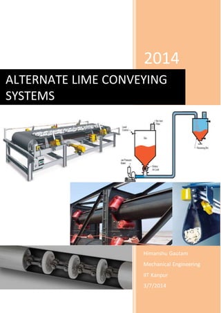
  • 1. 2014 Himanshu Gautam Mechanical Engineering IIT Kanpur 3/7/2014 ALTERNATE LIME CONVEYING SYSTEMS
  • 2. 1 PROPOSED PROJECT Exploring the Feasibility of Alternate Lime Conveying System from Lime Mill to Boiler Shree Cement Ltd., Beawar (May – July, 2014) Submitted to: Submitted by: Shree Rajeev Maheshwari Himanshu Gautam HOD, EEDC, 4th year UG Shree Cement Ltd., Dept. of Mechanical Eng. Beawar IIT Kanpur
  • 3. 2 ACKNOWLEDGEMENT I would liketo sincerelythank my project guide Mr.RajeevMaheshwari for his valuablesupport and guidance all through the project. I am extremely grateful for his technical and moral support during the course of my studies and I am highly indebted to him for the same. His meticulous guidance simplified the project work to an extent that in spite of some barriers like unavailability of any established data, the project work was successfully completed. I would like to thank Mr.Pankaj Gautam for providing me an excellent mentoring and encouragement and for sparing their precious time for discussions from their busy schedule. Besides I would like to thank Shree Cement Ltd. team who helped me directly or indirectly in completion of this project. I would specially like to mention the name of Mr. Anupam Roy Chowdhury for showing faith in me by selecting me for internship at Shree Cement Ltd. and taking a very good care during the course of this internship. He did an excellent job in managing all the interns from different colleges. I sincerely thanks Mr. Raj Nishchal Saraswat, Training In-charge (HRD dept.) and Mr. Gopal Tripathi (HRD dept.), Shree Cement Ltd, for extending all possible cooperation and providing excellent facilities to make the stay most comfortable. I am highly indebted to the people mentioned above and many other who have been an integral part of this project. Without them this project would have not been possible. Last but not the least; I am very thankful to Shree Cement Ltd for giving me the opportunity of having an on field experience in my department and providing all the available and necessary facilities for the same.
  • 4. 3 INDEX CONTENT 1. Project Details 2. Introduction to Pneumatic Conveying system 3. Liftube System 4. SPILL STOP SKIRT BOARD SEALING SYSTEM 5. Air Slider Gravity Conveyor System 6. Pipe Belt Conveyor 7. EBS Conveyor 8. Alternative conveying system suggestion 9. Final Results 10. Recommendation 11. Companies contacts
  • 5. 4 PROJECT DETAILS Study of the Pneumatic Lime conveyor systeminstalled at Shree Mega Power (2 X 150 Power Plant), Beawar and establish the guidelines to increase the efficiency of current system and to reduce power consumption. Alsopropose alternative lime conveyor systems which require minimal power consumption and hightransfer capacity. Propose solutions to reduce power consumption and increase conveying capacity wherever required. Project Guide: Shree Rajeev Maheshwari HOD, EEDC, Shree Cement Ltd. Project Sub-Guide: Shree Pankaj Gautam Manager, Shree Cement Ltd.
  • 6. 5 INTRODUCTION TO PNEUMATIC CONVEYING SYSTEM Pneumatic conveyor systems serve as an alternate to mechanical conveyors such as belts and vibrating trays. Instead of using traditional motors, they rely on air pressure to draw materials from various containers and transport them to other parts of the building for mixing or processing. Each conveyor utilizes either forced-air pressure or vacuum technology to push or pull materials using air. Forced-air systems are best for moving materials to multiple locations using a split tubing or pipe configuration, while vacuum units can only pull materials to a single location. Three basic systems that are used to generate high velocity air stream: 1. Suction or vacuum systems, utilizing a vacuum created in the pipeline to draw the material with the surrounding air. The system operated at a low pressure, which is practically 0.4–0.5 atm below atmosphere, and is utilized mainly in conveying light free flowing materials. 2. Pressure-type systems, in which a positive pressure is used to push material from one point to the next. The system is ideal for conveying material from one loading point to a number of unloading points. It operates at a pressure of 6 atm and upwards. 3. Combination systems, in which a suction system is used to convey material from a number of loading points and a pressure system is employed to deliver it to a number of unloading points.
  • 7. 6 ADVANTAGES OF PNEUMATIC CONVEYING The advantages of a pneumatic system compared with a mechanical conveyor system are: - Absence of dust dispersal in the environment; - Geometric flexibility of the conveyor system; - Simplicity of designing circuits that have several pick-up and unloading points; - Low maintenance costs. DISADVANTAGES OF PNEUMATIC CONVEYING - Makes it necessary to purchase a suitable machine, with high power consumption for achieving the necessary pressure gradient; - Solid conveying capacity lower than that of mechanical systems; - Limited distance along which the product can be conveyed; - Possible wear along the circuit in case of dilute phase flow; - Since complex fluid-dynamic phenomena are involved in pneumatic conveying systems, require very careful design of the conveyor circuit.
  • 8. 7 ALTERNATE CONVEYING SYSTEMS 1.Liftube System LIFTUBE is a modular system that optimises sealing of any existing conveyor belt (any width, any length, PVC, rubber, etc.), between the loading point and the unloading point. Instead of being in contact with idlers, the belt slides on a single central idler roller set up between lateral glide boards. Both idler roller and glide boards are tilt able to allow easy access when needed. A number of innovations could be implemented to facilitate operation and maintenance. At the glide boards and the tilting roller system, the conveyor belt and rollers are easily acces-sible. That means a drastic reduction in maintenance. The pinch point is protected and, thus, completely safe and conforms to European Norms. At the hood and lateral curtains, a drastic reduction of airborne dust, between loading and unloading, is observed which conforms to Norm ISO 14001 and represents a reduction of material losses. The product is totally protected. No material contamination is possible. In addition, a longer service life of the belt can be expected. The system is adaptable to every existing type of conveyor thanks to its standard, adaptable and evaluative components. A removable hood can be set up on top to ensure the reduction of airborne dust from the conveyor.
  • 9. 8 Components are standard; the dimensions of the central idler and hood will only vary with the width of the conveyor belt. Installation of the LIFTUBE is possible without changing the existing power consumption. The system allows a quick payback, normally in less than 18 months. By reducing the loss of product, the cost of cleaning is also reduced. Moreover, the costs of maintenance are reduced. Installations in all the business sectors concerned with bulk handling are possible. The LIFTUBE system can transport bulk products (fine - grading) (cement, lime, sugar …) as well as products of larger ­ sizes ­(limestone, chromium, iron, manganese …) and very abrasive ­ma­terials (aluminium oxide, coal …).   ADVANTAGES - Environment: reduction of airborne dust, between loading and unloading, conforms to ISO 14001. - Quality: the product is totally protected. No material contamination is possible - Complete safety : protection of pinch point - Drastic reduction in maintenance, made even simpler - Loading capacity: optimisation of conveying rates - Standard, adaptable, designed components - Installation of the LIFTUBE® without changing the existing power supply
  • 10. 9 2. SPILL STOP SKIRT BOARD SEALING SYSTEM Spill Stop Skirt Board Sealing System is a fool proof system comprising of Interlocking Sealing Blocks, Back Plate & Clamping Plate. The system is designed to suit all conveyors Advantages  Back Plate is permanently fixed to Skirt Plate of main equipment  Blocks can easily be adjusted to suit conveyor contour with a hammer  Long life of block when compared with rubber strips / cut belt conveyors  Very simple and quick installation  Easy Replaceable blocks at low cost  Increased productivity due to reduced spillage  Cleaner environment and reduced manpower required for cleaning  No damage to conveyor belt
  • 11. 10 3.Air Slider Gravity Conveyor System Airslide air gravity conveying system uses the forces of gravity to do most of the work without any moving parts. Airslide air gravity systems provide high capacity material handling while offering many economical and environmental advantages. Energy requirements are minimal because only a small volume of air at a low pressure is required to move material. Since the system is installed overhead, valuable floor space and added headroom are available for other purposes. By eliminating the need for massive support members, it permits a flexibility of plant design not available with straight-line conveyors. The Airslide conveyor is dust tight. As a result, the system is extremely friendly to the environment. Noise level is extremely low in the area surrounding the Airslide conveyor as the system’s air supply is the only moving part to generate noise, and it is generally located in a remotely insulated area to further reduce noise. Maintenance of the Airslide conveyor is very simple because there are no moving parts other than the air supply equipment, which also contributes to increased plant safety.
  • 12. 11 4.Pipe Belt Conveyor The pipe conveyor overcomes several of the problems commonly associated with conventional conveyors, e.g. spillage of material, belt training, limited angle of incline, horizontal curves and multiple flights. PIPE CONVEYOR CHARACTERISTICS Totally Enclosed Conveying Material being transported by a pipe conveyor is completely enclosed by the conveyor belt for the major portion of its travel. This has several benefits, including ■ environmental pollution is minimised as dust generation and en route spillage are eliminated, ■ the product is protected from outside contamination, and ■ valuable product is protected from theft along the conveyor’s path. Steep Inclined Conveying
  • 13. 12 Increased friction between the material and the pipe shape of pipe conveyors makes steep inclines possible, generally 50 % steeper than a conventional belt conveyor. This means that ■ the overall length of the conveyor system may be reduced, and ■ plant footprints can be smaller with further cost savings. Minimal Space Requirements The pipe conveyor is narrower than a conventional conveyor of the same capacity and uses less floor space. Return Belt Conveying The return belt is also formed into a pipe shape and can, in special circumstances, transport material. This offers cost advantages. Curved Transport The pipe shape of the belt permits the conveyor to curve horizontally as well as vertically. A single pipe conveyor can thus replace several conventional belt conveyors, reducing ■ the need for multiple transfer points and drives that require more space and cost, ■ power required to lift the product at repeated transfer points, ■ degradation of the product and dust generation at transfer points, and ■ costly chute liner replacements.
  • 14. 13 6.EBS Conveyor The heart of the EBS Conveyor is a fabric reinforced belt with solid rubber triangles vulcanised to both edges of the belt. The triangles are used for closing and supporting the belt in the conveyor structure. This way the belt hangs as a closed pouch beneath the rubber triangles and encloses the conveyed material. Features of the EBS Conveyor - Closed, almost dust free conveying - High capacities possible - Return part is closed, no spillage - Horizontal and vertical curves possible - Flexible routing, no transfer points needed - High angles of inclination possible - Simple and light conveyor structure, irrespective of length - Small radii for horizontal curves - Low maintenance costs due to simple conveyor lay-out - Multi-point drives - Belt is made out of one piece - System can easily be extended or shortened
  • 15. 14 Alternate conveying System suggestions 1.Using existing coal belt conveyor for lime powder conveying (Considering no lime spillage from belt 5(a,b)). Using Belt Sealing System Installing Belt Sealing System on belt conveyor for sealing on belt (3a,3b,4a,4b). Installing sealed chute system at loading and unloading points . Forming an opening on lime bunkers and a passage to the tripper trolley room . Considering no lime spillage from belt 5(a,b), tripper trolley can be used to transfer lime to lime Bunker 1 and 2. Calculation for 1 (A)option With Belt conveyor for loading : For belt conveyor motor power requirement : http://www.rulmecacorp.com/Motorized_Pulley_Metric_power_Calculations.html Power required for mill belt : 7.5 kw Power required for belt 3 : 30 kw Power required for belt 4 : 37 kw Power required for belt 5 : 22 kw Power required for Tripper trolley : 7.5 kw Total power = 104 kw Each day material to be conveyed = 1000 tonne Capacity : 20*6 = 120 tonne/hr Total hours : 1000/120 = 8.33 hr Power consumption each day : 8.33*104+(20% EXTRA) = 866.32 kwh Cost each day = 1039.58 * 3 = 3118 Rs Each year = 3118 * 300 = 935625.6 Rs Cost for each tonne = 3118/1000 = 3.1 Rs Yearly profit = ( 36 – 3.1 ) * 1000 * 300 = 9870000 Rs Things to be replaced or installed in existed belt conveyor system 1.Wing Idlers would be replaced by glide boards. 2.Lateral Curtains to stop the ingress of material between belt and glide boards. 3.Hood to make conveyor dust-tight. 4.Sealed chute system. Cost estimation Mill belt : 50 * 25000 = 1250000
  • 16. 15 Sealing system : ( 180 + 150 ) mt Cost per meter = 2650 Rs sealing cost = 874500 Rs Payback time = 2124500/9870000 = 0.21 years Calculation for 1(B)option with Air Slide conveyor for loading Power required for Air Slide(48 mt) : 5 kw * 4 = 20 kw Power required for belt 3 : 30 kw Power required for belt 4 : 37 kw Power required for belt 5 : 22 kw Power required for Tripper trolley : 7.5kw Total power = 116.5 kw Each day material to be conveyed = 1000 tonne Capacity : 20*6 = 120 tonne/hr Total hours : 1000/120 = 8.33 hr Power consumption each day : 8.33*116.5 +(20% EXTRA) = 1164.5 kwh Cost each day = 3459 Rs Each year = 1048500 Rs Cost for each tonne = 3.49 Rs Yearly profit = ( 36 – 2.53 ) * 1000 * 300 = 9751500 Rs Cost estimation Air Slide Loading System 4 Compressor = 60000 * 4 = 240000 Set up = 7500 per mt (30 mm) = 7500 * 50 = 375000 Sealing system : ( 180 + 150 ) mt Cost per meter = 2650 Rs Total cost = 874500 Rs Payback time = 1489500 / 9751500 = 0.15 years
  • 17. 16 2.Using existing coal belt conveyor for lime powder conveying.(Considering lime spillage from belt 5(a,b) ) Using Liftube System Modified chute design, the each division of current chute is further divided into two division, one on the belt 5 and another on new conveying belt. Install new pipe belt / Liftube belt conveying for transferring lime to lime bunker 2 from chute division. Power consumption in option 2 : Power = (Power consumption in option 1) – 7.5 kw – 22 kw + (Power consumption in new pipe belt in place of belt5) = 104 – 7.5 – 22 + 10 = 74.5 + 6 kw With pipe belt in place of belt 5 : power = 84.5 kw Each day power = 84.5 * 8.33 +(20% EXTRA) = 845 kwh Each day cost = 845 * 3 = 2535 Rs yearly cost = 1837.875 * 300 = 760500 Rs cost for 1 tonne = 2.53 Rs Profit = ( 36 – 2.53 ) * 300 * 1000 = 10039500 Rs Cost estimation Mill belt :50 * 25000 = 1250000 Sealing system :(180+150) mt Cost per meter = 2650 Rs Cost = 874500 Rs Cost of pipe conveyor in place of belt 5a = 30000 * 60 = 1800000 Rs Payback time = 3924500 / 10039500 = 0.4 years. Cost of sealed belt conveyor in place of belt 5a = 25000 * 60 = 1500000 Rs Payback time = 3624500 / 10039500 = 0.36 years. Power consumption in option 2 (b) with Air Slide Conveyor for loading : Power = (Power consumption in option 1) – 2 * (7.5) kw – 22 kw + (Power consumption in
  • 18. 17 new pipe belt in place of belt 5)+ (Power consumption in Air Slide Conveyor 50 mt ) = 104 – 2*7.5 – 22 + 10 + 20 = 97 kw Each day power = 97 * 8.33+(20% EXTRA) = 969.6kwh Each day cost = 969.6 * 3 = 2910 Rs yearly cost = 2910* 300 = 873000 Rs cost for 1 tonne = 2.9 Rs Profit = ( 36 – 2.9 ) * 300 * 1000 = 9930000 Rs Cost estimation AirSlide Loading System 4 Compressor = 60000 * 4 = 240000 Set up = 7500 per mt (300 mm) = 7500 * 50 = 375000 Sealing system : ( 180 + 150 ) mt Cost per meter = 2650 Rs Cost = 874500 Rs Cost of pipe conveyor in place of belt 5a = 30000 * 60 = 1800000 Rs Payback time = 3289500 / 9930000 = 0.33 years. Cost of sealed belt conveyor in place of belt 5a = 25000 * 60 = 1500000 Rs Payback time = 2989500 / 9930000 = 0.3 years. 4 Compressor = 60000 * 4 = 240000 Set up = 7500 per mt (300 mm) = 7500 * 50 = 375000 Sealing system : ( 180 + 150 ) mt Cost per meter = 2650 Rs Cost = 874500 Rs Cost of pipe conveyor in place of belt 5a = 30000 * 60 = 1800000 Rs Payback time = 3289500 / 9930000 = 0.331 years. Cost of sealed belt conveyor in place of belt 5a = 25000 * 60 =1500000Rs Payback time = 2989500 / 9930000 = 0.30 years.
  • 19. 18 3.Install a new Liftube belt conveyor system from lime plant to lime bunker 1 then (Liftube belt / pipe belt ) conveyor from bunker 1 to bunker 2. Calculations (CEMA Standard)(Belt Conveyor Loading) Design Capacity : 150 tph Belt Width : 800 mm BeltSpeed : 1 m/s For mill conveyor : 7.5 kw For Inclined conveyor Power required : 22 kw For Horizontal conveyor Power required : 11 kw For Bunker 1 to Bunker 2 (65 mt) Power required :7.5kw (Roller BeltConveyor) 10 kw (Pipe belt Conveyor) Total power : 50.5 kw * 8.33 hr : 416.5 kwh Each day cost : 1515 Rs Yearly Cost : 454500 Rs Cost for each tonne : 1.5 Rs Profit = (36 – 1.5) * 1000 * 300 : 10345500 Rs Installation Cost :
  • 20. 19 For sealed belt conveyor = (50 + 114 + 170 + 60) * 25000 = 9850000 Rs For steel Structure support = 2009400 Rs Total = 11859400 Payback period = 1.14 years Calculations(CEMA Standard )(with Air Slideloading) For Air Slide : 4 * 5 kw = 20 kw For Inclined conveyor Power required : 22 kw For Horizontal conveyor Power required : 11 kw For Bunker 1 to Bunker 2 (60 mt) Power required :7.5 kw (Roller BeltConveyor) 10 kw (Pipe belt Conveyor) Total power : 63 kw * 8.33 hr = 524.79 kwh Each day cost = 1890 Rs Yearly Cost = 567000 Rs Cost for each tonne = 1.89 Rs Profit = (36 – 1.89) * 1000 * 300 = 10230000 Rs Installation Cost : For Air Slide = 4 * 60000 + 50 * 7500 = 615000 Rs For sealed belt conveyor = (114 + 170 + 60) * 25000 = 8600000 Rs For steel Structure support = (114 + 170 +60) * 5100 = 1754400 Rs Total = 10969400 Rs Payback period = 1 years
  • 21. 20 4. Install a new Liftube belt conveyor system from lime plant to lime bunker 2 then (Liftube belt / pipe belt ) conveyor from bunker 2 to bunker 1. Calculations (CEMA Standard)(Belt Conveyor loading) Design Capacity : 150 tph Belt Width : 800 mm Belt Speed : 1 m/s For mill conveyor : 7.5 kw For Inclined conveyor Power required : 30 kw For Bunker 1 to Bunker 2 (60 mt) Power required :7.5 kw (Roller BeltConveyor) 10 kw (Pipe belt Conveyor) Total power : 47.5 kw * 8.33 hr = 395.7 kwh Each day cost = 1425 Rs Yearly Cost = 427500 Rs Cost for each tonne = 1.4 Rs Profit = (36 – 1.4) * 1000 * 300 = 10372500 Rs Installation Cost For sealed belt conveyor = (50 + 238 + 60) * 25000 = 8700000 Rs For steel Structure support = (50 + 238 + 60) * 5100 = 1774800 Rs Total = 10474800 Payback period = 1 years
  • 22. 21 Calculations(CEMA Standard )(With Air Slide for loading) For Air Slide = 4 * 5 kw = 20 kw For Inclined conveyor Power required = 30 kw For Bunker 1 to Bunker 2 (60 mt) Power required : 7.5 kw (Roller Belt Conveyor) 10 kw (Pipe beltConveyor) Total power : 60 kw * 8.33 hr = 500 kwh Each day cost = 1800 Rs Yearly Cost = 540000 Rs Cost for each tonne = 1.8 Rs Profit = (20 – 1.8) * 1000 * 300 = 10372500 Rs Installation Cost For Air Slide System = 4 * 60000 + 50 * 7500 + (238 + 60) * 25000 = 8065000 Rs For steel Structure support = 1774800 Rs Total =16438116 Rs Payback period = 0.95 years 5.Install a new pipe belt conveyor from lime mill to lime bunker 2 then (pipe belt / liftube belt) conveyor from bunker 2 to bunker 1.
  • 23. 22 Calculation for Belt conveyor (loading) and Pipe conveyor for conveying Input Parameters Design capacity : 150 tph Material Density : 1460 kg/m Belt Speed : 1 m/s Pipe Diameter : 0.2131 m Carry Spacing : 1.2 m Return Spacing : 3 m Belt Mass : 10 kg/m Idler Roll resistance : 1.25 N Pulley Friction Factor : 0.35 Angle of wrap : 210 Deg Drive Efficiency : 0.8 Friction factor : 0.03 Output Results : Power required : ( 30 + 5 ) = 35 kw Total power = 35 + 7.5 + 10 = 52.5 kw hours working = 1000 / 120 = 8.33 hr Each day Power requirement = 52.5 * 8.33 = 437.325 kwh Each day cost = 1575 Rs Yearly cost = 472500 Rs Each tonne cost = 1.57 Rs Profit = (36 – 1.57) * 1000 * 300 = 12386000 Rs Installing Cost: Rs 30000 per meter including carrying frame. Total = 50*25000 + ( 250 + 60 )*30000 + (50 + 250 + 60) * 5100 = 12386000 Rs. Payback period = 1.19 years Calculation for Air Slide (loading) and Pipe conveyor for conveying: Total power = (4 * 5) + 35 + 10 = 65 Hours working = 1000 / 120 = 8.33 Hr Each day Power requirement = 65 * 8.33 = 541.6 kwh Each day cost = 1950 Rs Yearly cost = 585000 Rs Each tonne cost = 1.95 Rs Profit = (36 – 1.95) * 1000 * 300 = 11751000 Rs
  • 24. 23 Installing Cost: Rs 30000 per meter including carrying frame (excluding civil work) Total = 4 * 60000 + 50 * 7500 + ( 250 + 60 )*30000 + (50 + 250 + 60) * 5100 = 240000 + 375000 + 9300000 + 1836000 = 11751000 Rs. Payback period = 1.15 years Final Results
  • 25. 24 Recommendation For Lime conveying System 3(a) with belt conveyor would be best since belt conveyor require less maintenance than pipe conveyor and a simple motor in place of 4 blower as comparison to air slide gravity conveyor. Conveyor Suppliers in India For Belt conveyor sealing : www.kaveri.in/ www.hoschonline.com/ www.martin-eng.com/ www.intersystems.net/ For Pipe conveyor system : www.macmet.co.in/ www.eleconepc.com/ www.thyssenkrupp-industries-india.com/ For DC-5 Air saver www.parthengineering.net/ For Air slide gravity conveyor www.akindia.com/ www.flsmidth.com/