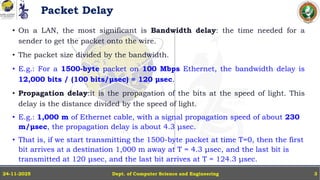
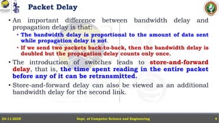
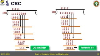
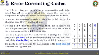
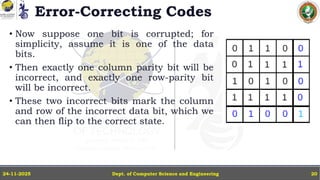
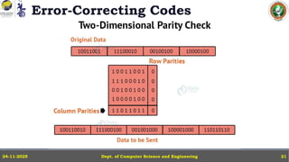
In this powerpoint slide decks the advances in computer network course offered discuss the computer network Packets, its format and Packet Delay, Variability, Packet Size, Error Detection.
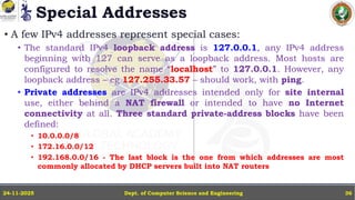
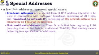
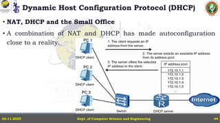
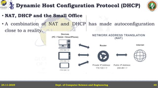
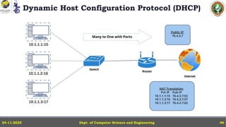
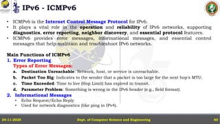
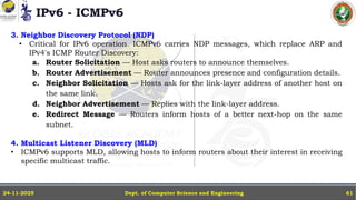
IP Version 4 - The IPv4 Header, Special Addresses, IPv4 Subnets, Dynamic Host Configuration Protocol (DHCP), IP version 6 - IPv6 Header, IPv6 addresses, IPv6 Host Address Assignment, ICMPv6.