SlideShare a Scribd company logo
Hydraulics & Automation

                     HƯỚNG DẪN LẮP ỐNG DẪN DẦU THỦY LỰC


                          KHOẢNG CÁCH CẮT ỐNG TỐI THIỂU
                          B
                          2


                                        B
                                        3


                CÁCH LẮP ĐẦU ỐNG VÀ ỐNG VÀO MÁY ÉP ĐẦU ỐNG
                B
                4


                                        B
                                        5


                                        1
Hydraulics & Automation

                     HƯỚNG DẪN LẮP ỐNG DẪN DẦU THỦY LỰC

                              CÁCH LẮP ỐNG CỨNG BẰNG TAY
                              B
                              6


                                           B
                                           7


                          CÁCH THÁO ĐẦU ỐNG BẰNG CHÌA VẶN
                          B
                          8


                                           B
                                           9


                                          2
Hydraulics & Automation

                     HƯỚNG DẪN LẮP ỐNG DẪN DẦU THỦY LỰC

                          CÁCH LẮP ĐẦU ỐNG BẰNG HÀN
                          B
                          0
                          1


                                         B
                                         1


                              CÁCH LẮP ĐẦU ỐNG ÉP LOE
                              B
                              2
                              1


B
3
1


                                         3
Hydraulics & Automation

                     HƯỚNG DẪN LẮP ỐNG DẪN DẦU THỦY LỰC


               SAI
               B
               4
               1                                  ĐÚNG


      B
      5
      1


  B
  6
  1


                                     4
Hydraulics & Automation

                     HƯỚNG DẪN LẮP ỐNG DẪN DẦU THỦY LỰC


                SAI
                B
                7
                1                                  ĐÚNG


     B
     8
     1


 B
 9
 1


                                     5
Hydraulics & Automation

                     HƯỚNG DẪN LẮP ỐNG DẪN DẦU THỦY LỰC


                          BÁN KÍNH UỐN ỐNG MỀM
                          B
                          0
                          2


             B
             1
             2


 B
 2


                                     6
Hydraulics & Automation

                         HƯỚNG DẪN LẮP ỐNG DẪN DẦU THỦY LỰC

              1 – ĐỦ KHÔNG GIAN CHO ỐNG CO GIÃN KHI CHỊU ÁP LỰC
                 B
                 0


                                         B
                                         3
                                         2


      SAI


                                                              ĐÚNG


               2 - ĐỦ KHOẢNG CÁCH CẦN THIẾT ĐỂ ỐNG KHÔNG BỊ CĂNG
                     B
                     1


                                         B
                                         4
                                         2


         SAI                                                  ĐÚNG


                                         7
Hydraulics & Automation

                     HƯỚNG DẪN LẮP ỐNG DẪN DẦU THỦY LỰC

             3 – SỬ DỤNG ĐẦU NỐI ĐỂ ỐNG CÓ CHIỀU DÀI NGẮN NHẤT
             B
             5
             2


                                       B
                                       6
                                       2


    SAI                                           ĐÚNG


                 4 – TRÁNH ĐỂ ỐNG LÀM VIỆC TRÊN HAI MẶT PHẲNG
                 B
                 7
                 2


                                       B
                                       8
                                       2


  SAI                               ĐÚNG


                                      8
Hydraulics & Automation

                       HƯỚNG DẪN LẮP ỐNG DẪN DẦU THỦY LỰC

               5 – SỬ DỤNG ĐẦU NỐI GÓC CHO SỐ GÓC UỐN ÍT NHẤT
               B
               9
               2


                                        B
                                        0
                                        3


                                            ĐÚNG
   SAI


                   6 – TRÁNH ĐỂ ỐNG BỊ VẶN XOẮN KHI CHUYỂN ĐỘNG
                   B
                   1
                   3


                                        B
                                        2
                                        3


                                      ĐÚNG


   SAI


                                        9
Hydraulics & Automation

                     HƯỚNG DẪN LẮP ỐNG DẪN DẦU THỦY LỰC

               7 – SỬ DỤNG ĐẦU NỐI CHUYỂN ÍT NHẤT ĐỂ TRÁNH RÒ RỈ
               B
               3


                                       B
                                       4
                                       3


                   SAI                              ĐÚNG

           8 – SỬ DỤNG ĐẦU NỐI 45, 90ĐỂ THU GỌN KHÔNG GIAN ĐI ỐNG
           B
           5
           3


                                       B
                                       6
                                       3


                          SAI                               ĐÚNG


                                      10
Hydraulics & Automation

                          HƯỚNG DẪN LẮP ỐNG DẪN DẦU THỦY LỰC

                      9 – ĐỂ KHÔNG GIAN CO GIÃN ỐNG KHI CHỊU ÁP
                      B
                      7
                      3


                                          B
                                          8
                                          3


                  10 – KHÔNG ĐỂ ỐNG BỊ VẶN XOẮN KHI LẮP ỐNG
                  B
                  9
                  3


                                          B
                                          0
                                          4


                                                                  ĐÚNG


    SAI


     11 – SỬ DỤNG ỐNG BỌC,KẸP CÁCH LY ỐNG VỚI ỐNG CÓ NHIỆT ĐỘ CAO
     B
     1
     4


                                          11
Hydraulics & Automation

                     HƯỚNG DẪN LẮP ỐNG DẪN DẦU THỦY LỰC

                                     B
                                     2
                                     4


 SAI


                                                          ĐÚNG


  12 – SỬ DỤNG CO 90 ĐỂ DỄ BẢO DƯỠNG, THÁO LẮP, KHÔNG GIAN GỌN GÀNG
  B
  3
  4


                                     B
                                     4


                                                          ĐÚNG
                             SAI


                                     12
Hydraulics & Automation

                     HƯỚNG DẪN LẮP ỐNG DẪN DẦU THỦY LỰC

  13 – KHÔNG ĐỂ ỐNG CÓ BÁN KÍNH UỐN QUÁ NHỎ SO VỚI BÁN KÍNH TỐI THIỂU
  B
  5
  4


                                     B
                                     6
                                     4


      SAI                          ĐÚNG


            14 – TRÁNH ỐNG CỌ XÁT VÀO VẬT CỨNG KHI CHUYỂN ĐỘNG
            B
            7
            4


                                     B
                                     8
                                     4


      SAI                                ĐÚNG


                                     13
GENERAL INFORMATION

     • STEEL USED ON ALL SERIES
     Carbon steel fittings
            Component                            Material specification                             Reference norm
                                CF9SMnPb36    CF9SMnPb28         CF9SMn36       CF9SMn28               UNI 4838
      Ring / sleeve
                                11SMnPb37     11SMnPb30          11SMn37        11SMn30                EN 10087
                                CF9SMnPb36    CF9SMnPb28         CF9SMn36       CF9SMn28               UNI 4838
      Nut
                                11SMnPb37     11SMnPb30          11SMn37        11SMn30                EN 10087
                                CF9SMnPb36    CF9SMnPb28         CF9SMn36       CF9SMn28               UNI 4838
      Straight body
                                11SMnPb37     11SMnPb30          11SMn37        11SMn30                EN 10087
                                CF9SMnPb36    CF9SMnPb28         CF9SMn36       CF9SMn28               UNI 4838
      Forged body
                                11SMnPb37     11SMnPb30          11SMn37        11SMn30                EN 10087

     Stainless steel fittings

            Component                            Material specification                             Reference norm
                                                                                                      DIN 17440
      Ring / sleeve             X6CrNiMoTi17-12-2 (1.4571)       X5CrNiMo17-12-2 (1.4401)
                                                                                                      EN 10088
                                                                                                      DIN 17440
      Nut                       X6CrNiMoTi17-12-2 (1.4571)       X2CrNiMo17-12-2 (1.4404)
                                                                                                      EN 10088
                                                                                                      DIN 17440
      Straight body             X6CrNiMoTi17-12-2 (1.4571)       X5CrNiMo17-12-2 (1.4401)
                                                                                                      EN 10088
                                                                                                      DIN 17440
      Forged body               X6CrNiMoTi17-12-2 (1.4571)       X5CrNiMo17-12-2 (1.4401)
                                                                                                      EN 10088


     • ALLOWED WORKING TEMPERATURES
     Carbon Steel -20° to + 120° degrees Celsius, according to ISO 8434
     Stainless steel -60° to + 200° degrees Celsius, according to ISO 8434


     • PRESSURE RATE REDUCTION
     The allowed working pressure for stainless steel fittings manufactured with 1.4571 must be reduced accor-
     ding to the working registered temperature as per ISO 8434. In case of multi-components systems all the
     parameters must be calculated on the weakest component used.
                Type of steel                 Working temperature                  Lowering percentage
                   1.4571                            ≥ 50°C                                 - 4%
                   1.4571                            ≥ 100°C                                - 11%
                   1.4571                            ≥ 200°C                                - 20%


     • GASKETS
     The gaskets used on valves and fittings are normally manufactured in NBR. All have a working temperature
     of -35° to +100° degrees Celsius with a hardness of 85 ± 5 shores. For higher temperatures Viton® seals
     are suggested with working temperatures between -25° to + 200° degrees Celsius with a hardness of 80 ± 5
     shores. All the items that are assembled with gaskets or seals of any kind must be handled according to the
     DIN 7716 norm (requisites for the stocking of rubber product).


     • SEAL ON THREADED ENDS
     To obtain the maximum performance, the taper male thread is to be matched with the taper female thread.
     The cylindrical male thread is to be matched with the cylindrical female thread. It is possible to match a
     taper male thread with a cylindrical female thread, but this combination is technically valid only in pipings
     where medium/low performances are required and is never to be used where high pressures are applied. In
     case of matching of a cylindrical thread with relatively soft material, it is advisable to use the plain gasket
     type of seal that guarantees a perfect sealing even with a relatively low tightening torque.


      VITON® is a DuPont Dow Elastomers Trade Mark

12
• CARBON STEEL FITTINGS FINISH TREATMENT
All fittings and valves are zinc-plated according to UNI ISO 2081 and 4520. The parts after treatment appear
white with yellow shades of color. The plating thickness is 8 ÷ 12 microns. This new treatment fully comply
to the latest EEC environmental directives as its hexavalent chromium free. The resistance in saline fog with
standard salt concentration ( test in accordance with UNI ISO 9227 ) is 400 hours before the protective
layer begins to wear off. Additionally, this treatment, chemically lubricate the items reducing as well torque
strength requirements. Due to this treatment the parts may be used also in external exposure provided that
the environment be not very aggressive. The cutting ring, after heat treatment to harden the surface, passi-
vation treatment and ecological zinc-plating, follows a bath which facilitates the assembly.

• STAINLESS STEEL FITTINGS FINISH TREATMENT
All the fittings and valves are treated with a chemical cleaning process which eliminate all oxides and burrs
due to the machining phase, without altering or damaging the product. After this, follows a bath to clean the
product and take away the last impurities, if any. The piece at the end of the treatment looks real bright, very
indicated for industrial applications where this type of steel is normally requested.

• THERMAL TREATMENT
The cutting rings after being machined are heat treated to harden the surface. This type of treatment, on
stainless steel cutting rings, may decrease the amagneticity of the ring itself.


STAINLESS STEEL FITTINGS                                  ANTI-SEIZING COMPOUND (NICKEL BASIS)
Seen the special characteristics of this type of          The anti-seizing compound (Nickel Basis) exposed
steel (hard but mild) particular attentions are           to a strong pressure originates "millions of grains
required to avoid problems. One of these require-         of Nickel" rolling between the surfaces. It allows a
ments is the correct lubrication of all the compo-        safer tightening and an easier unblocking. This
nents to be done during pre-assembling and                compound may be used both indoors and out-
assembling. Therefore is required to use the right        doors. It protects the threads from wearing out and
lubricant to make properly functional systems, at         breaking, keeps away rust and corrosion. Nickel
all times.                                                covers the connected surfaces avoiding any foun-
                                                          ding or welding and moreover there is only pure
                                                          colloidal nickel and no trace of carbonic deposits.
                                                          According to specification Mil. A 907 D.
                                                          Approved by the Ministry of Agriculture of the Uni-
                                                          ted States of America (USAD).
                                                          Packaging weight 227 gr. Art. 82356.


                                                          N.B.: Do not use on systems with oxygen or in the
                                                          presence of ammonia or acetylene.


                                                                                                                   13
• ALLOWED CARBON STEEL TUBES ON ALL SERIES
     • For steel tubes in mild carbon steel we advise to use calibrated seamless cold drawn without welding tubes ST 37.4 as
     per DIN 1630.

     • Maximum allowed hardness on the outside diameter of the tube is 75 HRB.

     • The indicated pressure are to be intended at a constant pressure rate and with temperatures between -20° and +120°
     degrees Celsius.


                                 Static     Dinamic                                                       Static     Dinamic
     ØTube Tolerance Thickness DIN 2413-I DIN 2413-III               Weight   ØTube Tolerance Thickness DIN 2413-I DIN 2413-III     Weight
      mm      mm        mm      pressure   pressure                  Kg/m      mm      mm        mm      pressure   pressure        Kg/m
                                   bar        bar                                                           bar        bar
       4      ±0,1       0,5      313         274                     0,047    18     ±0,08       2        313         274              0,789
       4                 1        522         502                     0,075    18      ±0,8       2,5      392         335              0,956
       6                 1        389         374                     0,123    18                 3        409         393              1,111
       6      ±0,1       1,5      549         528                     0,166    20     ±0,08       2**      282         249              0,888
       6                 2        692         665                     0,197    20                 2,5      353         305              1,079
       8                 1        333         289                     0,222    20      ±0,8       3        373         358              1,258
       8                 1,5      431         441                     0,240    20                 3,5      426         410              1,424
              ±0,1
       8                 2        549         528                     0,296    20                 4        478         460              1,578
       8                 2,5      658         632                     0,339    22                 2*       256         228              0,986
      10                 1        282         249                     0,222    22      ±0,8       2,5      320         280              1,202
      10                 1,5      373         358                     0,314    22                 3        385         329              1,406
      10      ±0,1       2        478         460                     0,395    25                 2*       226         202              1,134
      10                 2,5      576         553                     0,462    25                 2,5      282         249              1,387
      10                 3        666         641                     0,518    25     ±0,08       3        338         294              1,628
      12                 1*       235         210                     0,271    25                 4        394         379              2,072
      12                 1,5      353         305                     0,388    25                 4,5      437         420              2,275
      12                 2        409         393                     0,493    28                 2*       201         182              1,282
             ±0,08
      12                 2,5      495         476                     0,586    28     ±0,08       2,5      252         224              1,572
      12                 3        576         553                     0,666    28                 3        302         265              1,850
      12                 3,5      651         627                     0,734    30                 2**      168         171              1,381
      14                 1,5      302         265                     0,462    30                 2,5      235         210              1,695
                                                                                      ±0,08
      14                 2        403         343                     0,592    30                 3        282         249              1,998
      14     ±0,08       2,5      434         417                     0,709    30                 4        376         323              2,565
      14                 3        507         487                     0,814    35                 2*       161         147              2,189
      14                 3,5      576         553                     0,906    35     ±0,15       2,5      201         182              2,004
      15                 1,5      282         249                     0,499    35                 3        242         216              2,367
      15     ±0,08       2        376         323                     0,641    35                 4        322         281              3,058
      15                 3        478         460                     0,888    38       ±         3**      223         200              2,589
      16                 1,5**    264         234                     0,536    38     ±0,15       4        297         261              3,354
      16                 2        353         305                     0,691    38                 5        371         319              4,069
             ±0,08
      16                 2,5      386         372                     0,832    42                 3        201         182              2,885
                                                                                       ±0,2
      16                 3        452         435                     0,962    42                 4        269         238              3,749
      18     ±0,08       1,5*     235         210                     0,610

     * Tubes that require support sleeve if used for DIN 2353 applications
     ** Tubes to be used for ISO 8434-2 / SAE J514 norm only


     CALCULATION PRESSURES

     The calculation of pressure with static load is made to DIN 2413-I with yield point K=235N/mm2.
     For tubes with external/internal diameter ratio >1.35 calculation is made to DIN 2413-III but with yield point K=235N/mm2.
     The calculation of pressures with dynamic stress is made to DIN 2413-III with permanent fatigue strength K=226N/mm2.
     Safety factor S=1.5. Allowance factor c=0.8 for diameter tube 4mm, c=0.85 for diameter tube 6-8mm, c=0.9 for diameter tube >8mm.
     Corrosion: additional allowance are not considered for calculation of pressures.


14
• ALLOWED STAINLESS STEEL TUBES ON ALL SERIES
• For steel tubes in stainless steel we advise to use calibrated seamless cold drawn without welding tubes 1.4571 as per
DIN 17458 or ASTM A269.

• Maximum allowed hardness on the outside diameter of the tube is 85 HRB.

• The indicated pressure are to be intended on a constant pressure rate and with temperatures between -60° and +200°
degrees Celsius.


                                   Static                                                                Static
       ØTube Tolerance Thickness DIN 2413-I               Weight              ØTube Tolerance Spessore DIN 2413-I            Weight
        mm      mm        mm      pressure                Kg/m                 mm      mm       mm      pressure             Kg/m
                                     bar                                                                   bar
         4      ±0,1
                ±0,1       0,5      326                    0,048               18                2        326                 0,801
         4                 1        544                    0,076               18      ±0,8      2,5      409                 0,971
         6                 1        406                    0,125               18                3        426                 1,128
         6      ±0,1       1,5      572                    0,169               20                2**      294                 0,902
         6                 2        721                    0,200               20                2,5      368                 1,095
         8                 1        347                    0,225               20      ±0,8      3        389                 1,277
         8                 1,5      449                    0,244               20                3,5      444                 1,446
                ±0,1
         8                 2        572                    0,301               20                4        498                 1,602
         8                 2,5      686                    0,344               22                2*       267                 1,001
        10                 1        294                    0,225               22      ±0,8      2,5      334                 1,220
        10                 1,5      389                    0,319               22                3        401                 1,427
        10      ±0,1       2        498                    0,401               25                2*       236                 1,151
        10                 2,5      601                    0,469               25                2,5      294                 1,408
        10                 3        694                    0,526               25     ±0,08      3        352                 1,653
        12                 1*       245                    0,275               25                4        411                 2,104
        12                 1,5      368                    0,394               25                4,5      456                 2,310
        12                 2        426                    0,500               28                2*       210                 1,301
               ±0,08
        12                 2,5      516                    0,595               28     ±0,08      2,5      263                 1,596
        12                 3        601                    0,676               28                3        315                 1,878
        12                 3,5      679                    0,745               30                2**      175                 1,402
        14                 1,5      315                    0,469               30                2,5      245                 1,721
                                                                                      ±0,08
        14                 2        420                    0,601               30                3        294                 2,028
        14     ±0,08       2,5      452                    0,720               30                4        392                 2,604
        14                 3        529                    0,826               35                2*       168                 2,222
        14                 3,5      601                    0,920               35                2,5      210                 2,034
                                                                                      ±0,15
        15                 1,5      294                    0,507               35                3        252                 2,403
        15     ±0,08       2        392                    0,651               35                4        336                 3,104
        15                 3        498                    0,902               38                3**      232                 2,628
        16                 1,5**    275                    0,544               38     ±0,15      4        310                 3,405
        16     ±0,08       2        368                    0,702               38                5        387                 4,131
        16                 2,5      402                    0,845               42                3        210                 2,929
                                                                                       ±0,2
        16                 3        471                    0,977               42                4        280                 3,806
        18     ±0,08       1,5*     245                    0,619

      * Tubes that require support sleeve if used for DIN 2353 applications
      ** Tubes to be used for ISO 8434-2 / SAE J514 norm only


CALCULATION PRESSURES

The calculation of pressure with static load is made to DIN 2413-I with yield point K=245N/mm2.
For tubes with external/internal diameter ratio >1.35 calculation is made to DIN 2413-III but with yield point K=245N/mm2.
Pressures with dynamic stress according to DIN 2413-III are not listed because in DIN 17458 the permanent fatigue stress K is also not
listed.
We recommend for calculation in accordance to DIN 2413 III to assume a value K=190N/mm2.
Safety factor S=1.5, Allowance factor c=0.9.
Corrosion: additional allowance are not considered for calculation of pressures.


• The not sufficient thickness of the tube walls, or the too low longitudinal resistance of the tubes ( particularly mild soft steel ) may create
problems of the cutting ring with the according losses of seals and the drastical decrease of safety factor. While choosing the tube this aspect
must be considerate. Is good rule to pick tubes so that the internal flare ( decreasing of the internal diameter ) do not exceed the 3/10 of a
millimeter up to outside diameter of 16mm and 4/10 of a millimeter on higher diameters.


                                                                                                                                                    15
• COMPATIBLE FLUIDS TABLE
     The following table resumes, according to the compatibility with the used fluid, the best possible choice as com-
     bination between the fitting type of steel ( carbon or stainless steel ), material of the elastomeric seal ( NBR or
     Viton® ) and type of sealing ( plain metal to metal or metal plus elastomeric sealing).


                              Fluid                     Carbon       Stainless        NBR           VITON®
                                                         steel         steel
             Acetiylen                                    •             •              •              •
             Aceton                                       •             •              •              •
             Hidrocloric Acid                             •             •              •              •
             Phosphoric Acid                              •             •              •              •
             Nitrico Acid                                 •             •              •              •
             Solforic Acid                                •             •              •              •
             Water                                        •             •              •              •
             Distilled water                              •             •              •              •
             Sea water                                    •             •              •              •
             Hidrogen peroxide                            •             •              •              •
             Turpentine                                   •             •              •              •
             Ammonia gas, cold                            •             •              •              •
             Ammonia liquid                               •             •              •              •
             Carbonic dioxide                             •             •              •              •
             Argon                                        •             •              •              •
             Air                                          •             •              •              •
             Compressed air                               •             •              •              •
             ASTM-Oil, n°1                                •             •              •              •
             ASTM-Oil, n°2                                •             •              •              •
             ASTM-Oil, n°3                                •             •              •              •
             Nitrogen                                     •             •              •              •
             Benzene                                      •             •              •              •
             Sulfur oxide                                 •             •              •              •
             Carbon bisolfure                             •             •              •              •
             Butane                                       •             •              •              •
             Clorine                                      •             •              •              •
             Helium                                       •             •              •              •
             Etane                                        •             •              •              •
             Ether                                        •             •              •              •
             Combustibile gas                             •             •              •              •
             Natural gas                                  •             •              •              •
             Natural gas untreated                        •             •              •              •
             Diesel fuel                                  •             •              •              •
             Glycerin                                     •             •              •              •
             Glycol                                       •             •              •              •
             Hidrogen                                     •             •              •              •
             Iodine                                       •             •              •              •
             Kerosene                                     •             •              •              •
             Methane                                      •             •              •              •
             Methanol                                     •             •              •              •
             Fuel oil                                     •             •              •              •


16
Fluid                        Carbon   Stainless   NBR   VITON®
                                                steel     steel
 Neon                                            •         •        •      •
 Oil                                             •         •        •      •
 Heating fuel oil                                •         •        •      •
 Automotive brake fluid                          •         •        •      •
 Transmission fluid                              •         •        •      •
 Mineral oil                                     •         •        •      •
 Natural mineral oil                             •         •        •      •
 Hydraulic oil                                   •         •        •      •
 Vegetable oil                                   •         •        •      •
 Carboni monoxide                                •         •        •      •
 Oxygen                                          •         •        •      •
 Ozone                                           •         •        •      •
 Pentane                                         •         •        •      •
 Pentane liquid                                  •         •        •      •
 Propane                                         •         •        •      •
 Silicone                                        •         •        •      •
 Styrol                                          •         •        •      •
 Toluol                                          •         •        •      •
 Trichloroethylene                               •         •        •      •
 Steam                                           •         •        •      •
 Xylol                                           •         •        •      •


  Legenda

• = Sufficient
• = Scarce
• = Not recommended
• = Not sufficient data
VITON® is a DuPont Dow Elastomers Trade Mark


                                                                                   17
PRESCRIPTIONS TO COMPLY WITH ON ALL SERIES
     • Use only CAST S.p.A. components for the same assembly
     • Apply completely the General Instructions, Utilization Norms, Safety Factors, Assembly Instruction and
     Working Pressures for the specific fitting is used.
     • Respect the working temperature rates and temperature related pressure rate reduction, if any.
     • Respect the indicated tightening values as well as the assembly instructions.
     • Lubricate all the components, as indicated in the assembly instructions, with specific products.
     • All tubes must be properly pre-assembled or flared before being assembled on machine board. Is not
     allowed to pre-assemble directly on machine board.
     • All stainless steel parts must be assembled on hardened tools and all stainless steel tubes must be pro-
     perly pre-assembled or flared before being assembled on machine board. Is not allowed to preassemble
     directly on machine board.
     • Use only high quality carbon and stainless steel tubes as per our indication on pages 14 and 15.
     • Use support sleeves on thin tubes.
     • Is not allowed to mix different materials ( carbon and stainless steel ) in the same connection.
     • Always check the correct alignment of the system.
     • Always check the correct incision of the cutting ring on the tube.
     • Is not allowed, in any case, to use non conform tubes or fittings, as well as is not allowed to make non
     conform assembly.
     • Is not allowed to alter in any way CAST S.p.A. products.
     • Fully comply to all technical information indicated in this catalogue.
     • In case of doubt always refer to the prudence concept.

     Not following any of these prescription may alter greatly the functionality of the products causing problems
     to the system, and the immediate loss of all products guarantees.


     • PRODUCT LIABILITY
     73. D.P.R. 224-CEE 85/347 states that " ... the responsibility will be charged to the negligent part ... "
     This means that the manufacturer will be held responsible if, and only if, the product was effectively faulty.
     The distributor that has done the final sale shall check, under its own responsibility, that its final customer
     was well aware of all technical problems inherent to the product used such as assembly instructions, and
     that the product was used for the right application.
     On the same line the end user will be considered responsible part if did not follow completely the written
     prescriptions of the manufacturer ( General Catalogue ) that must be notified to him by the part doing the
     sale. Should the end user be short of this technical documentation CAST S.p.A. will be glad to send it direc-
     tly.
     In view of this European norm CAST S.p.A. declines any responsibility in the case which the user fails to
     comply strictly and entirely with the General Instruction, Utilization Norms, Safety Factors, Assembly
     Instruction and Working Pressures as any other technical information clearly indicated in this General Cata-
     logue as failure to these prescriptions may affect the functional safety of the products and results in voiding
     the user's warranty rights.
     As per the quoted norm there is a 500,00 franchise.


18
B3


B3
STANDARD DOUBLE CUTTING EDGE RING ASSEMBLED
ON ALL CAST PRODUCTION ASSURES SEALING AND SAFETY

AVAILABLE IN CARBON AND STAINLESS STEEL
                                                    19
B3

          THEORY OF OPERATION
          The Cast fitting, manufactured according to ISO 8434-1/DIN 2353 norm is a mechanical fitting with a dou-
          ble cutting ring for double stapling on the tube.
          The ring helps fast assembly of removable tubes, avoids welding, tapping and flaring, thus assuring maxi-
          mum simplicity of complex oleo-dynamic systems.
          During tightening by the nut, the ring deforms according to the bore of the 24° cone of the fitting and bites
          into the steel tube, producing two deep cuts the first of which is visible due to lifting of an outer edge on the
          diameter of the tube, allows the water tightness and anti-unthreading of the ring. The second groove (invisi-
          ble) balances the forces on the whole ring, prevents vibrations to reach the first groove and stops the sta-
          pling of the tube at a predetermined value.


     COUPLING                                                                                                    Reference
     SYSTEM                                                                                                      prescriptions:
     DIN 2353

                                                                                                                 ST 37.4 tube
                                                                                                                 DIN 1630-2391


                                                                                                                 Nut
                                                                                                                 DIN 3870


                                                                                                                 Cutting ring
                                                                                                                 DIN 3861-B


     Traceability                                                                                                Shape of housing
     decoding                                                                                                    DIN 3861

             =
     Manufacturer

     •T=
     Production plant                                                                                            Fitting body
                                                                                                                 DIN 3901
     •0=
     Year manufactured

     • CE =
     Made in EEC

     • 38 =                                                                                                      Metal to metal seal
     Type of steel                                                                                               DIN 3852-1B/2B
     used

     • 01 =
     Heat number of                                                                                              Threaded end
     the steel used                                                                                              DIN 3852


20
B3

TECHNICAL CHARACTERISTICS
The Cast fitting assures a perfect seal, independently from the fluid used, provided that no corrosive fluids
be employed and the nominal pressures not be trespassed. Fittings are manufactured in three ranges to be
chosen according to the required working conditions.
"LL" extra light range, suitable for low and medium working pressures up to 100 bar.
"L" light range, suitable for medium/high pressure applications, however not over 315 bar.
"S" heavy range, for severe conditions, with high pressures, water hammering, high temperatures and a
maximum pressure of 630 bar.
Vibrations according to the standards, don't change the fitting's performance that, even at maximum values
keeps its characteristics of absolute reliability.


Before assembly on the metal tube


After assembly on the metal tube


                                         3

                                    1    2


Field of force after assembly      Pressure surfaces after assembly      Sealing points
                                                                         1-2-3


                                                                                                                21
B3


     DETAIL OF B3 CUTTING RING SEALING POINTS
     Cutting ring: 100110
     Tube: Ø22x1,5
     Cutting ring assembly: one full turn on fitting body as per DIN 3859-2 norm
     Magnifying: Microscope x5
     Detail scale: 0,5


                                    SEALING POINT 1 – FIRST CUTTING EDGE


                                  SEALING POINT 2 – SECOND CUTTING EDGE


                                           SEALING POINT 3 – 24° CONE


22
B4


B4
NEW SIX-SEALS CUTTING RING.
INTERNATIONAL INDUSTRIAL PATENT Nr. 864061 of the 10/03/99
FLANKS AND DOES NOT REPLACE THE STANDARD RING CURRENTLY IN USE

AVAILABLE IN CARBON AND STAINLESS STEEL                          23
B4

            THEORY OF OPERATION
            The “B4” is a highly innovative, deformable, double clinching, double edge ring with double elastomer seal
            that is assembled according to well-known techniques and is perfectly interchangeable with all types of
            rings used on 24° cone fittings complying with the ISO 8434-1/DIN 2353 standards.
            The ring helps fast assembly of removable tubes, avoids welding, tapping and flaring, thus assuring maxi-
            mum simplicity of complex oleo-dynamic systems.
            During tightening by the nut, the ring deforms according to the bore of the 24° cone of the fitting and bites
            into the steel tube, producing two deep cuts the first of which is visible due to lifting of an outer edge on the
            diameter of the tube, allows the water tightness and anti-unthreading of the ring. The second groove (invisi-
            ble) balances the forces on the whole ring, prevents vibrations to reach the first groove and stops the sta-
            pling of the tube at a predetermined value.


     COUPLING                                                                                                    Reference
     SYSTEM                                                                                                      prescriptions:
     DIN 2353

                                                                                                                 ST 37.4 tube
                                                                                                                 DIN 1630-2391


                                                                                                                 Nut
                                                                                                                 DIN 3870

                                                                                                                 O-Ring

                                                                                                                 Cutting ring
                                                                                                                 DIN 3861-B

                                                                                                                 Flat washer
                                                                                                                 seal

     Traceability                                                                                                Shape of housing
     decoding                                                                                                    DIN 3861

             =
     Manufacturer

     •T=
     Production plant                                                                                            Fitting body
                                                                                                                 DIN 3901
     •0=
     Year manufactured
                                                                                                                 Flat
     • CE =                                                                                                      washer housing
     Made in EEC                                                                                                 DIN 3852-11E

     • 38 =
     Type of steel
     used

     • 01 =
     Heat number of                                                                                              Threaded end
     the steel used                                                                                              DIN 3852


24
B4

TECHNICAL CHARACTERISTICS
The “B4” ring assures perfect tightness of the circuit regardless of the fluid used provided that corrosive
fluids are avoided and the nominal pressures of the fittings are complied with. The fittings on which the
“B4” rings are mounted are manufactured in two series that are used according to the operating conditions.
“L” light duty series for applications characterized by medium high pressures, maximum 315 bar.
“S” heavy duty series for harsh applications characterized by high temperatures and a maximum pressure
of 630 bar.
“B4” performance is not affected by vibrations within normal limits and the product maintains its optimal
characteristics, as an absolutely safe ring, even at maximum values.
When the fitting, ring, nut, tube system is assembled, the flat seal is compressed between the head of the
cutting ring and the front of the fitting body. The mechanical pressure applied to the flat seal causes flexure
towards the outside, with a consequent increase in diameter. The deformation causes the compressed
material of the seal to fill the turns of the thread of the nut free from the closing coupling with the fitting
body, assuring locking of the nut and preventing any vibration-induced loosening of this.
When the fitting is disassembled the flat seal goes back to its original shape, without any damage, freeing
the nut threads.


Before assembly on the metal tube


After assembly on the metal tube


                                                     6

                                                5
                                        3

                                   1        2                   4


Field of force after assembly       Pressure surfaces after assembly         Sealing points
                                                                             1-2-3-4-5-6


                                                                                                                  25
B4


     109. DETAIL OF B4 CUTTING RING SEALING POINTS
     Cutting ring: 100110.4
     Tube: Ø22x1,5
     Cutting ring assembly: one full turn on fitting body as per DIN 3859-2 norm
     Magnifying: Microscope x5
     Detail scale: 0,5


                        SEALING POINT 1                                       SEALING POINT 4
                      FIRST CUTTING EDGE                                          O-RING


                       SEALING POINT 2                                      SEALING POINT 5
                     SECOND CUTTING EDGE                            FLAT WASHER SEAL ON FITTING BODY


                        SEALING POINT 3                                    SEALING POINT 6
                           24° CONE                                FLAT WASHER SEAL IN NUT THREADS


26
B4

TECHNICAL INNOVATION
For many years now, there has been an increasing imperative market demand for fluid system components
able to guarantee three main factors: safety, easy assembly, leakage-free tightness.
These elements, now considered essential for safety of the working environment (Law 626/94), product lia-
bility (Presidential Decree 224-EEC 85/374) and for the entire environmental protection system have promo-
ted the development of the new “B4” ring as an effective response to all the above-mentioned problems.


PRODUCT CONCEPT
The most original aspect of the product is that the structure of the existing ring has been used, inserting an
O-Ring in the inside part to obtain another seal on the tube used and a flat seal on the outer diameter to
obtain two additional seals.
The main idea behind the development of the “B4” was to design a new cutting ring able to go one step
beyond the known techniques and to solve the problem of minor losses of tightness, leaks, sweating and
loosening of the system fastening nut.
With this new ring, the double clinching of the steel tube is still possible and as well as, for obvious rea-
sons of safety, the visual inspection of correct coupling between the ring and the steel tube, maintaining the
current, perfectly functional system of assembly that is widely known to product users.


SEALING
“B4” solves the problem of absolute tightness in the following way:

• On the outer diameter of the steel tube, with the double cutting edges and with an O-Ring placed inside the
ring that provides a first seal with an elastomeric material that didn’t exist before.
• In the 24° cone of the fitting body, with an increase in the metal-on-metal contact area and with a flat seal,
placed statically on the outer diameter of the cutting ring which, when compressed between the head of the
ring and the front of the fitting body, provides a second seal with an elastomeric material that didn’t exist
before.
• In the thread of the system fastening nut, with the flat seal. When this is compressed between the head of
the ring and the front of the fitting body, it fills the threads of the nut that are not engaged in clinching of the
coupling system, thus providing a third seal with an elastomeric material that didn’t exist before.
• Basically, the “B4” provides six points of seal of which three metal to metal and three by means of two
soft elastomeric seals (the flat seal assures two sealing points) thus obtaining a product able to assure
complete tightness without any possibility of leakage even in particularly harsh operating conditions.


                                                                                                                       27
B3-B4

       GENERAL INSTRUCTIONS FOR B3 AND B4 RINGS
       • Before starting the preassembly make sure that the pierce of the machine and the hardened blocks are in
       perfect working order. Further inspections are necessary during the preassembly (every 30-50 tightenings).
       For this purpose we advise to use a control buffer 1000… pierce and replace any block out of tolerance.
       • Over the whole tightening phase the tube must be in touch with the inner part of the body of the fitting. If
       this does not happen, the ring will advance with the tube without indenting it, so the coupling would not be
       functional and it would be necessary to do the operation again. The tube must not turn with the nut during
       the tightening phase; the capability of the ring to rotate, once the pre-assembly is done, is not a deficiency
       but is a consequence of the right elasticity of the ring. Always check that the tube be correctly indented. If
       the indentation does not cover 80% of the ring front side then the assembly is not functional and must be
       done again. Indicated pressures are for steel tubes only.
       • In case thin wall tubes are used, specially mild tubes, or tubes in Rilsan or similar, the assembling is pos-
       sible, but a suitable reinforcement must be inserted into the end of the tube that is going to be tightened.
       Without the reinforcement it is not possible to operate with the above mentioned materials.
       • Before assembling the preassembled tube to the equipment it is necessary to check that the tube and the
       fitting are aligned. Fitting should never be used to correct a wrong alignment or to be a support for the tube.
       Extremely long tubes or tubes undergoing high stress have absolutely to be fixed by using some support to
       avoid excessive vibrations that could cause damage to the system.
       • The proper lubrication of components involved in the tightening is basic for good working.
       We advise to use mineral oils for carbon steel fittings and anti-seizing compound (Nickel basis) for Stain-
       less steel fittings.
       • The fittings and the valves in this technical catalogue may the used for fluido-dynamic connections only.
       • Is not allowed to mix carbon and stainless steel components.


       UTILIZATION STANDARDS FOR B3 AND B4 CUTTING RINGS

       CARBON STEEL FITTINGS
       • High quality tubes must be employed to assure correct use and related technical performance of carbon
       steel fitting. Use of tubes without the aforementioned characteristics may seriously impair the efficiency of
       the fitting. We recommend use of the following tubes only: ST 37.4 steel seamless tubes complying with
       DIN 1630, inner and outer diameter tolerances as per DIN 2391, maximum permissible hardness, measured
       on the outer diameter of the tube is 75 HRB.
       • All carbon steel tubes with a diameter of more than 10 mm must be pre-assembled using the specific
       preassembly machine. If this is not available, hardened blocks, to be clamped in vice for manual preassem-
       bly, must be used. Remember to oil the thread, nut and ring. If hardened pre-assembly blocks are not avai-
       lable, normal straight fittings can be used. The fitting used once must be replaced at each tightening. During
       preassembly, pay particular attention to parts such as reducing standpipes and nipples as these are made of
       raw materials characterized, therefore, by higher resistance compared with the cuts made on annealed
       tubes. These parts must always be pre-assembled on hardened 24° cones (for all diameters).


       STAINLESS STEEL FITTINGS
       • High quality tubes must be employed to assure correct use and related technical performance of stainless
       steel fitting. Use of tubes without the aforementioned characteristics may seriously impair the efficiency of
       the fitting. We recommend use of the following tubes only: cold drawn seamless tube 1.4571 as per DIN
       17458 or ASTM A 269, maximum permitted hardness, measured on the outer diameter of the tube, measu-
       red on the outer diameter of the tube is 85 HRB. Electrically welded tubes may be used provided they com-
       ply with the mechanical tolerances of the aforementioned standards and related hardness values.
       • All stainless steel tubes must be pre-assembled using the specific preassembly machine. If this is not
       available, hardened blocks must be used for manual preassembly. In this case, make sure that the bench
       and vice in which the block is clamped are firmly fastened to prevent any possibility of movement caused by
       the twisting moment applied to the nut during the preassembly phase. Assembly or preassembly operations
       directly on the fitting are not allowed.


28
B3-B4

QUALITY ASSURANCE ACCORDING TO UNI EN ISO 9001
The Quality Assurance System complies with UNI EN ISO 9001, certificate (N°90/94) issued by the RINA
certification authority recognized by IQNET at European level.
CAST S.p.A. has also obtained the DVGW product omologation for stainless steel fittings, and DNV product
omologation for carbon and stainless steel fittings with B3 and B4 cutting rings.
At the customer’s request, our Quality Service will issue certificates of origin for the materials used to
manufacture the products delivered.
Our Quality Experts are always ready to provide customers with advice, to guide them around our facilities
as to provide documentation of the traceability system applied.


COMPONENT TESTING
In addition to the normal dimensional checks carried out during machining, percentage inspections of the
finished product, practical tightness and fatigue tests, coupling tests between the various parts are also car-
ried out on CAST fittings. At the customer’s request, our Product Test and Inspection Service issues the
certificate of the tests carried out: dimensional and geometrical tests, checking of static seal at low and high
pressure, dynamic seal at high pressure (maximum operating pressure + 33%) as per ISO 8434-5.
If required by the customer, tests can be carried out by various Third Party Authorities including: RINA –
DVGW – Lloyd’s Register of Shipping – Det Norske Veritas – Germanischer Lloyd – American Bureau of
Shipping (to be specified on the order).


SAFETY FACTORS
• B3 and B4 rings provide the right answer to safety problems so that absolute functional reliability
between the ring, the steel tube and the fitting body is guaranteed by the double clinching and automatic
locking of the cuts on the steel tube (assured by the particular shape of the ring).
• CAST’s product range fully complies with the construction parameters of reference standards.
• The nominal operating pressures (bar) given in the catalogue indicate the maximum permissible pressures
(including pressure peaks). For higher pressure the items must be tested in accordance with the manufac-
turer for specific applications.
• The safety factor is 4:1 and is intended with static load and with the temperature at the values indicated as
per DIN 3861 (24° cone) for tube connection. The same safety factor 4:1 is intended for parallel threaded
end fittings with elastomeric seal. For stud couplings with taper or parallel threaded end fittings with metal
to metal seal safety factor is 2,5:1.
• Is understood that the product is guaranteed only if the full connection is made entirely with CAST S.p.A.
products and components.


Destructive testing with 28x2 carbon steel tube
The tube burst at 650 bar without any leakages or sweating from the sealing points


                                                                                                                   29
B3-B4

     STUD ENDS DIN 2353 WITH BSPP THREAD


      Serie    ØTube       BSPP              D4 min     D4 min     L1       L2     L       Torque (Nm) Torque (Nm) Torque (Nm) Torque (Nm)
                          Thread     D3      form B/E   form G/H   max      min    rif       form B         form E      form H         form G
                  6       G 1/8       9,8      15        17,2      1         8     7,5         20             20         20              20
                  8       G 1/4      13,2      20        20,7      1,5      12    10,2         45             45         45              45
                 10       G 1/4      13,2      20        20,7      1,5      12    10,2         45             45         45              45
                 12       G 3/8      16,7      23        24,5      2        12    10,4         70             70         70              70
        L        15       G 1/2      21        28        29,6      2,5      14    13,1        130             85         85              85
                 18       G 1/2      21        28        29,6      2,5      14    13,1        130             85         85              85
                 22       G 3/4      26,5      33        36,9      2,5      16    13,5        170            170        170             170
                 28       G1         33,3      41        46,1      2,5      18    14,7        330            330        330             330
                 35       G 1 1/4    42        51        54        2,5      20    14,7        510            430        430             430
                 42       G 1 1/2    47,9      56        60,5      2,5      22    14,7        600            510        510             510
                  6       G 1/4      13,2      20        20,7      1,5      12    10,2         55             55         55              55
                  8       G 1/4      13,2      20        20,7      1,5      12    10,2         55             55         55              55
                 10       G 3/8      16,7      23        24,5      2        12    10,4         85             80         80              80
                 12       G 3/8      16,7      23        24,5      2        12    10,4         85             80         80              80
        S        14       G 1/2      21        28        29,6      2,5      14    13,1        150            110        110             110
                 16       G 1/2      21        28        29,6      2,5      14    13,1        150            110        110             110
                 20       G 3/4      26,5      33        36,9      2,5      16    13,5        280            170        170             170
                 25       G1         33,3      41        46,1      2,5      18    14,7        330            330        330             330
                 30       G 1 1/4    42        51        54        2,5      20    14,7        510            430        430             430
                 38       G 1 1/2    47,9      56        60,5      2,5      22    14,7        680            510        510             510

     Performances:                          Sealing form B:              Sealing form E:              Sealing form H:            Sealing form G:
     - Pressure capacity                    Good                         Excellent                    Excellent                  Excellent
     - Sealing characteristics              Good                         Excellent                    Excellent                  Excellent
     - Additional sealing required          no                           no                           no                         no
     - Safety factor                        2,5:1                        4:1                          4:1                        4:1


30   *In revision phase
B3-B4

STUD ENDS DIN 2353 WITH METRIC THREAD


 Serie    ØTubo      Metric           D4 min     D4 min     L1       L2     L       Torque (Nm) Torque (Nm) Torque (Nm) Torque (Nm)
                    Thread      D3    form B/E   form G/H   max      min    rif       form B         form E      form H          form G
             6      M10x1       10      15         16       1         8     7,6         20             20         20              20
             8      M12x1,5     12      18         19       1,5      12     9,7         30             30         30              30
            10      M14x1,5     14      20         21       1,5      12     9,7         45             45         50              50
            12      M16x1,5     16      23         24       1,5      12    10,2         60             55         55              55
            15      M18x1,5     18      25         26       2        12    10,9         80             70         70              70
   L        18      M22x1,5     22      28         29       2,5      14    12          130            120        120             120
            22      M26x1,5     26      33          -       2,5      16     -          180            170         -               -
            22      M27x2       27      33         34       2,5      16    13,8         -              -         170             170
            28      M33x2       33      41         43       2,5      18    13,8        330            330        330             330
            35      M42x2       42      51         52       2,5      20    13,8        470            430        430             430
            42      M48x2       48      56         57       2,5      22    15,3        600            510        510             510
             6      M12x1,5     12      18         19       1,5      12     9,7         40             40         40              40
             8      M14x1,5     14      20         21       1,5      12     9,7         55             55         55              55
            10      M16x1,5     16      23         24       1,5      12    10,2         80             70         70              70
            12      M18x1,5     18      25         26       2        12    10,9        105             85         85              85
            14      M20x1,5     20      27         27       2        14    12          150            120        120             120
   S
            16      M22x1,5     22      28         29       2,5      14    12          170            130        130             130
            20      M27x2       27      33         34       2,5      16    13,8        200            170        170             170
            25      M33x2       33      41         43       2,5      18    13,8        390            330        330             330
            30      M42x2       42      51         52       2,5      20    13,8        510            430        430             403
            38      M48x2       48      56         57       2,5      22    15,3        680            510        510             510

Performances:                        Sealing form B:              Sealing form E:              Sealing form H:            Sealing form G:
- Pressure capacity                  Good                         Excellent                    Excellent                  Excellent
- Sealing characteristics            Good                         Excellent                    Excellent                  Excellent
- Additional sealing required        no                           no                           no                         no
- Safety factor                      2,5:1                        4:1                          4:1                        4:1
                                                                                                                                            31
B3-B4

     STUD ENDS DIN 2353 WITH METRIC THREAD (ISO 6149)


               P max        P max                Metric                                                          Torque (Nm) Torque (Nm)
      Serie   ISO 6149     ISO 6149    ØTube                 D2      D5     L1      L3      L4      L      Z°     ISO 6149     ISO 6149
              STRAIGHT    ADJUSTABLE             Thread      min                    max    min      rif           STRAIGHT    ADJUSTABLE
                 315          315          6    M10x1        16     11,1    1,6     1      10      8,6     12        15           15
                 315          315          8    M12x1,5      19     13,8    2,4     1,5    11,5   11,1     15        25           25
                 315          315        10     M14x1,5      21     15,8    2,4     1,5    11,5   11,1     15        30           30
                 315          250        12     M16x1,5      24     17,8    2,4     1,5    13     11,6     15        35           35
       L         315          250        15     M18x1,5      26     19,8    2,4     2      14,5   12,3     15        40           40
                 315          250        18     M22x1,5      29     23,8    2,4     2      15,5   13,4     15        55           55
                 160          160        22     M27x2        34     29,4    3,1     2      19     15,8     15        85           85
                 160          160        28     M33x2        43     35,4    3,1     2,5    19     15,8     15       140          140
                 160          160        35     M42x2        52     44,4    3,1     2,5    19,5   15,8     15       180          180
                 160          160        42     M48x2        57     50,4    3,1     2,5    22     17,3     15       230          230
                 630          400         6     M12x1,5      19     13,8    2,4     1,5    11,5   11,1     15        30           30
                 630          400         8     M14x1,5      21     15,8    2,4     1,5    11,5   11,1     15        40           40
                 630          400        10     M16x1,5      24     17,8    2,4     1,5    13     11,6     15        50           50
                 630          400        12     M18x1,5      26     19,8    2,4     2      14,5   12,3     15        60           60
                 400          400        14     M20x1,5      27     21,8    2,4     2      14,5   13,4     15        70           70
       S
                 400          400        16     M22x1,5      29     23,8    2,4     2      15,5   13,4     15        85           85
                 400          400        20     M27x2        34     29,4    3,1     2      19     15,8     15       150          150
                 400          315        25     M33x2        43     35,4    3,1     2,5    19     15,8     15       260          260
                 250          250        30     M42x2        52     44,4    3,1     2,5    19,5   15,8     15       280          280
                 250          200        38     M48x2        57     50,4    3,1     2,5    22     17,3     15       360          360

     Performances:                             STRAIGHT sealing:                  ADJUSTABLE sealing:
     - Pressure capacity                       Excellent                          Excellent
     - Sealing characteristics                 Excellent                          Excellent
     - Additional sealing required             no                                 no
     - Safety factor                           4:1                                4:1

     N.B. To obtain the ISO 6149 type of sealing please take out the retaining ring from the standard fitting.
32
B3-B4

 STUD ENDS DIN 2353 WITH UNF/UN-2A THREAD


 Serie ØTube          UNF/UN-2A       D2                 L3     L4     L            Torque (Nm) Torque (Nm)
                        Thread       min     D5     L1   max    min    rif     Z°    STRAIGHT    ADJUSTABLE
            6      7/16-20 UNF-2A     21   12,45   2,4   1,6   11,5    9,9     12       20          20
            8       1/2-20 UNF-2A     23   14,05   2,4   1,6   11,5    9,9     12       25          25
           10       1/2-20 UNF-2A     23   14,05   2,4   1,6   11,5    9,9     12       25          25
           12      9/16-18 UNF-2A     25   15,7    2,5   1,6   12,7   11,1     12       30          30
           15       3/4-16 UNF-2A     30   20,65   2,5   2,4   14,3   12,5     15       45          45
   L       18       3/4-16 UNF-2A     30   20,65   2,5   2,4   14,3   12,5     15       45          45
           18       7/8-14 UNF-2A     34   24      2,5   2,4   16,7   14,5     15       55          55
           22     1 1/16-12 UN-2A     41   29,2    3,3   2,4   19     16,8     15       85          85
           28     1 5/16-12 UN-2A     49   35,55   3,3   3,2   19     16,8     15      130         130
           35      1 5/8-12 UN-2A     58   43,55   3,3   3,2   19     16,8     15      170         170
           42      1 7/8-12 UN-2A     65   49,9    3,3   3,2   19     16,8     15      180         180
            6       1/2-20 UNF-2A     23   14,05   2,4   1,6   11,5    9,9     12       25          25
            8       1/2-20 UNF-2A     23   14,05   2,4   1,6   11,5    9,9     12       25          25
           10      9/16-18 UNF-2A     25   15,7    2,5   1,6   12,7   11,1     12       35          35
           12      9/16-18 UNF-2A     25   15,7    2,5   1,6   12,7   11,1     12       35          35
           14       3/4-16 UNF-2A     30   20,65   2,5   2,4   14,3   12,5     15       60          60
   S       16       3/4-16 UNF-2A     30   20,65   2,5   2,4   14,3   12,5     15       60          60
           16       7/8-14 UNF-2A     34   24      2,5   2,4   16,7   14,5     15       85          85
           20     1 1/16-12 UN-2A     41   29,2    3,3   2,4   19     16,8     15      150         150
           25     1 5/16-12 UN-2A     49   35,55   3,3   3,2   19     16,8     15      230         230
           30      1 5/8-12 UN-2A     58   43,55   3,3   3,2   19     16,8     15      250         250
           38      1 7/8-12 UN-2A     65   49,9    3,3   3,2   19     16,8     15      320         320


Performances:                       STRAIGHT sealing:    ADJUSTABLE sealing:
- Pressure capacity                 Excellent            Excellent
- Sealing characteristics           Excellent            Excellent
- Additional sealing required       no                   no
- Safety factor                     4:1                  4:1


                                                                                                              33
B3-B4

        STUD ENDS DIN 2353 WITH BSPT THREAD
        STUD ENDS DIN 2353 WITH NPT THREAD


              Serie    ØTube        BSPT                        Serie    ØTube             NPT
                                   Thread       L1       L2                              Thread          L1
                          6        R 1/8         5,5     9,5                6          1/8-27 NPT       11,6
                          8        R 1/4         8,5    13,5                8          1/4-18 NPT       16,4
                         10        R 1/4         8,5    13,5               10          1/4-18 NPT       16,4
                         12        R 3/8         8,5    13,5               12          3/8-18 NPT       17,4
                L        15        R 1/2        10,5    16,5      L        15          1/2-14 NPT       22,6
                         18        R 1/2        10,5    16,5               18          1/2-14 NPT       22,6
                         22        R 3/4        13      19                 22          3/4-14 NPT       23,1
                         28        R1            -       -                 28            1-11,5 NPT     27,8
                         35        R 1 1/4       -       -                 35         1 1/4-11,5 NPT    28,3
                         42        R 1 1/2       -       -                 42         1 1/2-11,5 NPT    28,3
                          6        R 1/4         8,5    13,5                6          1/4-18 NPT       16,4
                          8        R 1/4         8,5    13,5                8          1/4-18 NPT       16,4
                         10        R 3/8         8,5    13,5               10          3/8-18 NPT       17,4
                         12        R 3/8         8,5    13,5               12          3/8-18 NPT       17,4
                         14        R 1/2        10,5    16,5               14          1/2-14 NPT       22,6
                S                                                 S
                         16        R 1/2        10,5    16,5               16          1/2-14 NPT       22,6
                         20        R 3/4        13      19                 20          3/4-14 NPT       23,1
                         25        R1            -       -                 25            1-11,5 NPT     27,8
                         30        R 1 1/4       -       -                 30         1 1/4-11,5 NPT    28,3
                         38        R 1 1/2       -       -                 38         1 1/2-11,5 NPT    28,3


        Performances:                        Sealing form C:   Performances:                      Taper sealing:
        - Pressure capacity                  Low-Medium        - Pressure capacity                Low-Medium
        - Sealing characteristics            Low-Medium        - Sealing characteristics          Low-Medium
        - Additional sealing required        yes               - Additional sealing required      yes
        - Safety factor                      2,5:1             - Safety factor                    2,5:1


34
B3-B4

STUD ENDS DIN 2353 WITH METRIC TAPER THREAD


                 Serie    Ø Tube       Metric
                                    Taper Thread      L1     L2
                             6      M10x1 keg         5,5   10
                             8      M12x1,5 keg       8,5   13,5
                   L        10      M14x1,5 keg       8,5   13,5
                            12      M16x1,5 keg       8,5   13,5
                            15      M18x1,5 keg       8,5   13,5
                            18      M22x1,5 keg      10,5   15,5
                             6      M12x1,5 keg       8,5   13,5
                             8      M14x1,5 keg       8,5   13,5
                            10      M16x1,5 keg       8,5   13,5
                   S
                            12      M18x1,5 keg       8,5   13,5
                            14      M20x1,5 keg      10,5   15,5
                            16      M22x1,5 keg      10,5   15,5


                Performances:                      Sealing form C:
                - Pressure capacity                Low-Medium
                - Sealing characteristics          Low-Medium
                - Additional sealing required      yes
                - Safety factor                    2,5:1


                                                                             35
B3-B4

        TIGHTENING TORQUES FOR B3 AND B4 CUTTING RINGS
        DIN 3861 cone for carbon and stainless steel


                  Assembly of B3                                                      Assembly of B4
                    cutting ring                                                        cutting ring


                                           Metric      Manual   Manual      Machine   Machine
                        Serie   ØTube                  Carbon   Stainless   Carbon    Stainless
                                           Thread       (Nm)      (Nm)        (Kg)      (Kg)
                                    6      M12x1,5       20        30        1200      1400
                                    8      M14x1,5       25        55        1400      1700
                                   10      M16x1,5       30        85        2000      2200
                                   12      M18x1,5       40       120        2100      2400
                                   15      M22x1,5       60       130        2400      3300
                          L
                                   18      M26x1,5       90       220        2500      3600
                                   22      M30x2        170       320        2600      3800
                                   28      M36x2        210       500        3000      6900
                                   35      M45x2        360       970        5500     10000
                                   42      M52x2        490      1110        6700     12500
                                    6      M14x1,5       25        45        1200      1400
                                    8      M16x1,5       30        55        1400      1700
                                   10      M18x1,5       40        90        2000      2200
                                   12      M20x1,5       50       105        2100      2400
                                   14      M22x1,5       70       150        2400      3300
                          S
                                   16      M24x1,5       80       180        2500      3600
                                   20      M30x2        140       340        2600      6400
                                   25      M36x2        230       530        5000      9300
                                   30      M42x2        300       610        5500     10000
                                   38      M52x2        430       850        6700     12500


        Notes:

        All the values reported in the above tightening tables are mere indication, and come from a series
        of practical tests carried out in the technical laboratory of Volpiano (TO). These may vary accor-
        ding to the materials and to the tolerances of the employed components.

        All the values express in Newton Meters (Nm) for the tightening torques on the cone DIN 3861
        threads represent the torquing moment necessary to have the correct incision of the pre-assembly
        of the tube, lifting the required 80% of the front of the edge of the cutting ring.

        All the values expressed in Kilograms (Kg) for the linear push on the preassembly machine, repre-
        sent the right strength necessary to have the correct incision of the preassembly lifting the requi-
        red 80% of the front of the edge of the cutting ring.

        Once done properly the preassembly and checked that all the components are conforming to the
        requirements of the system, finish the assembly on the system itself, first closing by wrench until
        you feel a certain resistance, and then doing the last 1/4 of a turn to close the fitting completely.


36
B3-B4

SERIES 60… SWIVEL NUT


According to DIN 2353 standards, 24° sealing head as per DIN 2861 and O-Ring seal as per DIN 3865.

This series of fittings with revolving nut and seal on the 24° sealing cone guaranteed by an o-ring,
meets customers requirements when asking for high pressure, absolute tightness low tightening
torque.

Because of its technical characteristics this type of fitting is suitable for demanding applications
such as assembly on heavy machinery. The result is a safe fastening of the nut to the body impro-
ving the whole sealing system.

The limit of this series was given by the fact that the preformed sealing with o-ring was limited to a
single connection, leaving all the others with the old solutions.

A new step forward was needed to improve the research and find a solution that could grant a dou-
ble sealing system on all the connections involved, metal to metal plus the elastomeric sealing.

This problem has been solved by CAST S.p.A. with the new B4 ring guaranteeing a double sealing,
metal to metal plus the elastomeric sealing on all the connections of the fitting.


TIGHTENING TORQUES FOR SWIVEL NUT FITTINGS
DIN 3861 cone for carbon and stainless steel


                                Serie   ØTube        Metric      Torque
                                                    Thread        (Nm)
                                           6        M12x1,5         20
                                           8        M14x1,5         35
                                          10        M16x1,5         40
                                          12        M18x1,5         45
                                          15        M22x1,5         55
                                  L
                                          18        M26x1,5        110
                                          22        M30x2          130
                                          28        M36x2          200
                                          35        M45x2          220
                                          42        M52x2          240
                                           6        M14x1,5         40
                                           8        M16x1,5         45
                                          10        M18x1,5         50
                                          12        M20x1,5         60
                                          14        M22x1,5         80
                                  S
                                          16        M24x1,5        100
                                          20        M30x2          160
                                          25        M36x2          240
                                          30        M42x2          260
                                          38        M52x2          350

Notes:

All the values reported in the above tightening tables and mere indication, and come from a series
of practical tests carried out in the technical laboratory of Volpiano (TO). These may vary according
to the materials and to the tolerances of the employed components.

All the values express in Newton Meters (Nm) for the tightening torques, represent the torquing
moment necessary to have the correct tightness.


                                                                                                         37
B3-B4

        DEFINITION OF CONE SIZE TO DIN 3861 STANDARDS
        THREAD DIAMETERS TO DIN 3853 STANDARDS
        Allowed for B3 and B4 rings


                                            Metric
                   Serie   Bar    ØTube    Thread    d1     d2B11   d4+0,1   L3   L8+0,3
                                       4   M8x1       3      4       5        8    4
                    LL     100         6   M10x1      4,5    6       7,5      8    5,5
                                       8   M12x1,5    6      8       9,5      9    5,5
                                       6   M12x1,5    4      6       8,1     10    7
                                       8   M14x1,5    6      8      10,1     10    7
                           250        10   M16x1,5    8     10      12,3     11    7
                                      12   M18x1,5   10     12      14,3     11    7
                                      15   M22x1,5   12     15      17,3     12    7
                     L
                                      18   M26x1,5   15     18      20,3     12    7,5
                           160
                                      22   M30x2     19     22      24,3     14    7,5
                                      28   M36x2     24     28      30,3     14    7,5
                           100        35   M45x2     30     35      38       16   10,5
                                      42   M52x2     36     42      45       16   11
                                       6   M14x1,5    4      6       8,1     12    7
                                       8   M16x1,5    5      8      10,1     12    7
                           630        10   M18x1,5    7     10      12,3     12    7,5
                                      12   M20x1,5    8     12      14,3     12    7,5
                                      14   M22x1,5   10     14      16,3     14    8
                     S
                                      16   M24x1,5   12     16      18,3     14    8,5
                           400        20   M30x2     16     20      22,9     16   10,5
                                      25   M36x2     20     25      27,9     18   12
                                      30   M42x2     25     30      33       20   13,5
                           250
                                      38   M52x2     32     38      41       22   16


38
SAE


SAE J514
THE CAST 37° STANDARDIZED FITTINGS
AN EASY ASSEMBLY
A KNOWN PRODUCT, SAFE AND RELIABLE

AVAILABLE IN CARBON AND STAINLESS STEEL
                                                39
SAE

            THEORY OF OPERATION
           The CAST S.p.A. fitting according to the norms ISO 8434-2/ SAE J514, is a mechanical fitting traditionally
           used for high pressure oleo-dynamic systems.
           The sealing is made by the contact between two metal surfaces, with no deformation of the single compo-
           nents.
           The coupling between the body of the fitting and the flared tube (cone angle 74°) is guaranteed by the tigh-
           tening nut and by the pressure sleeve on the inside. This allow to realize a fast assembling-disassembling
           tube making the easiest realization of complex oleo-dynamic systems.


     COUPLING                                                                                               Reference
     SYSTEM                                                                                                 prescriptions:
     SAE J514
                                                                                                            ST 37.4 tube
                                                                                                            DIN 1630-2391


                                                                                                            Pressure sleeve
                                                                                                            ISO 8434-2/SAE J514


                                                                                                            Nut
                                                                                                            ISO 8434-2/SAE J514


                                                                                                            37° cone

     Traceability
     decoding

             =
     Manufacturer

     •T=
     Production plant

     •0=                                                                                                    Fitting body
     Year manufactured                                                                                      ISO 8434-2

     • CE =
     Made in EEC                                                                                            Flat
                                                                                                            washer housing
     • 38 =                                                                                                 ISO 1179-2.2
     Type of steel
     used

     • 01 =
     Heat number of                                                                                         Threaded end
     the steel used                                                                                         ISO 1179-2.2


40
SAE

TECHNICAL CHARACTERISTICS
The CAST S.p.A. 37° fitting grants a perfect sealing of the system independently from the used fluid, as long
as corrosive fluids are not used and all the specific prescription for this type of fitting are complied with.
These fittings are manufactured in a single series defined “UNIVERSAL” since the body and the nut of the
fitting remain the same even when switching from a inches sized tube to a metric tube, and since there are
no doubles of diameters with different working pressures.
Vibrations, in the norm, do not alter the functionality of this type of fitting, also at the top level of the quoted
values, and therefore keeps the best characteristics of absolute guarantee, safety and reliability. For these
specific reasons this fitting may be used in hard working conditions.
Under the mechanical strength given by the tightening of the nut on the fitting body, the flared 37° part of
the tube couples with the conical 37° part of the fitting body giving birth to a metal to metal seal.
The pressure sleeve hosted in the inside part of the nut assures the correct alignment of the system dimini-
shing the vibrations and avoiding any possible trouble or damaging of the tube during the assembly phase.


Before assembly on the metal tube


After assembly on the metal tube


                                                  1


Field of force after assembly       Pressure surfaces after assembly          Sealing points
                                                                              1


                                                                                                                       41
SAE

       DETAIL 37° CONE SEALING POINTS
       Tube: Ø25x2
       Assembly: as per tightening torque indicated on this catalogue (160Nm)
       Magnifying: Microscope x5
       Detail scale: 0,5


                                            180. SEALING POINT 1 – 37° CONE


       PRODUCT MATURITY
       For many years now, there has been an increasing imperative market demand for fluid system components
       able to guarantee three main factors: safety, easy assembly, leakage-free tightness.
       These elements, now considered essential for safety of the working environment (Law 626/94), product lia-
       bility (Presidential Decree 224-EEC 85/374) and for the entire environmental protection system make the
       37° flared fitting an effective response to all the above-mentioned problems.


                                                Standard SAE J514 fitting
                                                   with no elastomeric
                                               seal available on scheduled
                                                       orders only.


42
SAE


SAE J514
THE NEW CAST 37° FITTINGS WITH O-RING
A DRY AS THE DUST SEAL
AN EASY ASSEMBLY
A KNOWN PRODUCT, SAFE AND RELIABLE

AVAILABLE IN CARBON AND STAINLESS STEEL
                                                43
Adaptor fundamental
Adaptor fundamental
Adaptor fundamental
Adaptor fundamental
Adaptor fundamental
Adaptor fundamental
Adaptor fundamental
Adaptor fundamental
Adaptor fundamental
Adaptor fundamental
Adaptor fundamental
Adaptor fundamental
Adaptor fundamental
Adaptor fundamental
Adaptor fundamental
Adaptor fundamental
Adaptor fundamental
Adaptor fundamental
Adaptor fundamental
Adaptor fundamental
Adaptor fundamental
Adaptor fundamental
Adaptor fundamental
Adaptor fundamental
Adaptor fundamental
Adaptor fundamental
Adaptor fundamental
Adaptor fundamental
Adaptor fundamental
Adaptor fundamental
Adaptor fundamental
Adaptor fundamental
Adaptor fundamental
Adaptor fundamental
Adaptor fundamental
Adaptor fundamental
Adaptor fundamental
Adaptor fundamental
Adaptor fundamental
Adaptor fundamental
Adaptor fundamental
Adaptor fundamental
Adaptor fundamental

More Related Content

Viewers also liked

Hydraulic Fittings to Din 2353
Hydraulic Fittings to Din 2353Hydraulic Fittings to Din 2353
Hydraulic Fittings to Din 2353
Panarc Techno-metier
 
Gates Brochure
Gates BrochureGates Brochure
Gates Brochure
ERIKS UK
 
Gear men
Gear menGear men
Gear men
IKHWAN WAHAB
 
Samsung Gear S3 SM-R770- SM-760- Final User Manual
Samsung Gear S3 SM-R770- SM-760- Final User ManualSamsung Gear S3 SM-R770- SM-760- Final User Manual
Samsung Gear S3 SM-R770- SM-760- Final User Manual
TizenExperts
 
Use of rapid prototyping method for manufacture and examination of gear wheel...
Use of rapid prototyping method for manufacture and examination of gear wheel...Use of rapid prototyping method for manufacture and examination of gear wheel...
Use of rapid prototyping method for manufacture and examination of gear wheel...
Saras Chandra
 
2014 new catalogue jtw-series machine screw jack,machine screw jack worm gear...
2014 new catalogue jtw-series machine screw jack,machine screw jack worm gear...2014 new catalogue jtw-series machine screw jack,machine screw jack worm gear...
2014 new catalogue jtw-series machine screw jack,machine screw jack worm gear...Jacton Electromechanical Co.,Ltd
 
Asymmetrical gear analysis
Asymmetrical gear analysisAsymmetrical gear analysis
Asymmetrical gear analysis
Sachin Yadagudi
 
GEAR BOX FUNDAMENTAL ASHUTOSH MOHANTY
GEAR BOX FUNDAMENTAL ASHUTOSH MOHANTYGEAR BOX FUNDAMENTAL ASHUTOSH MOHANTY
GEAR BOX FUNDAMENTAL ASHUTOSH MOHANTY
Ashutosh Mohanty
 
Gear coupling catalogue
Gear coupling catalogueGear coupling catalogue
Gear coupling catalogueKalyan Halder
 
INTRODUCTION OF GEARS AND GEAR KINEMATICS
INTRODUCTION OF GEARS AND GEAR KINEMATICSINTRODUCTION OF GEARS AND GEAR KINEMATICS
INTRODUCTION OF GEARS AND GEAR KINEMATICS
Kiran Wakchaure
 
thiết kế khuôn nhựa vi si hoàn chỉnh
thiết kế khuôn nhựa vi si hoàn chỉnh thiết kế khuôn nhựa vi si hoàn chỉnh
thiết kế khuôn nhựa vi si hoàn chỉnh
Trung tâm Advance Cad
 
Gear milling
Gear millingGear milling
Gear milling
Aditya Shilame
 
Gear and Screw measurement
Gear and Screw measurementGear and Screw measurement
Gear and Screw measurement
AFAQAHMED JAMADAR
 
Thiết kế kim loại tấm -Sheetmetal Solidworks (demo)
Thiết kế kim loại tấm -Sheetmetal Solidworks (demo)Thiết kế kim loại tấm -Sheetmetal Solidworks (demo)
Thiết kế kim loại tấm -Sheetmetal Solidworks (demo)
Trung tâm Advance Cad
 
Gear metrology
Gear metrologyGear metrology
Gear metrology
Ravish Roy
 
Gear thread
Gear threadGear thread
Gear thread
IMS
 
Introduction to gears
Introduction to gearsIntroduction to gears
Introduction to gears
Naseel Ibnu Azeez
 
Lathe machining presentation
Lathe machining presentationLathe machining presentation
Lathe machining presentationAZIZCO
 

Viewers also liked (20)

Hydraulic Fittings to Din 2353
Hydraulic Fittings to Din 2353Hydraulic Fittings to Din 2353
Hydraulic Fittings to Din 2353
 
Gates Brochure
Gates BrochureGates Brochure
Gates Brochure
 
Gear men
Gear menGear men
Gear men
 
Automotive Engineering MSc
Automotive Engineering MScAutomotive Engineering MSc
Automotive Engineering MSc
 
Samsung Gear S3 SM-R770- SM-760- Final User Manual
Samsung Gear S3 SM-R770- SM-760- Final User ManualSamsung Gear S3 SM-R770- SM-760- Final User Manual
Samsung Gear S3 SM-R770- SM-760- Final User Manual
 
Use of rapid prototyping method for manufacture and examination of gear wheel...
Use of rapid prototyping method for manufacture and examination of gear wheel...Use of rapid prototyping method for manufacture and examination of gear wheel...
Use of rapid prototyping method for manufacture and examination of gear wheel...
 
2014 new catalogue jtw-series machine screw jack,machine screw jack worm gear...
2014 new catalogue jtw-series machine screw jack,machine screw jack worm gear...2014 new catalogue jtw-series machine screw jack,machine screw jack worm gear...
2014 new catalogue jtw-series machine screw jack,machine screw jack worm gear...
 
Asymmetrical gear analysis
Asymmetrical gear analysisAsymmetrical gear analysis
Asymmetrical gear analysis
 
Giaotrinhthietketopsolid
GiaotrinhthietketopsolidGiaotrinhthietketopsolid
Giaotrinhthietketopsolid
 
GEAR BOX FUNDAMENTAL ASHUTOSH MOHANTY
GEAR BOX FUNDAMENTAL ASHUTOSH MOHANTYGEAR BOX FUNDAMENTAL ASHUTOSH MOHANTY
GEAR BOX FUNDAMENTAL ASHUTOSH MOHANTY
 
Gear coupling catalogue
Gear coupling catalogueGear coupling catalogue
Gear coupling catalogue
 
INTRODUCTION OF GEARS AND GEAR KINEMATICS
INTRODUCTION OF GEARS AND GEAR KINEMATICSINTRODUCTION OF GEARS AND GEAR KINEMATICS
INTRODUCTION OF GEARS AND GEAR KINEMATICS
 
thiết kế khuôn nhựa vi si hoàn chỉnh
thiết kế khuôn nhựa vi si hoàn chỉnh thiết kế khuôn nhựa vi si hoàn chỉnh
thiết kế khuôn nhựa vi si hoàn chỉnh
 
Gear milling
Gear millingGear milling
Gear milling
 
Gear and Screw measurement
Gear and Screw measurementGear and Screw measurement
Gear and Screw measurement
 
Thiết kế kim loại tấm -Sheetmetal Solidworks (demo)
Thiết kế kim loại tấm -Sheetmetal Solidworks (demo)Thiết kế kim loại tấm -Sheetmetal Solidworks (demo)
Thiết kế kim loại tấm -Sheetmetal Solidworks (demo)
 
Gear metrology
Gear metrologyGear metrology
Gear metrology
 
Gear thread
Gear threadGear thread
Gear thread
 
Introduction to gears
Introduction to gearsIntroduction to gears
Introduction to gears
 
Lathe machining presentation
Lathe machining presentationLathe machining presentation
Lathe machining presentation
 

Recently uploaded

Essentials of Automations: Optimizing FME Workflows with Parameters
Essentials of Automations: Optimizing FME Workflows with ParametersEssentials of Automations: Optimizing FME Workflows with Parameters
Essentials of Automations: Optimizing FME Workflows with Parameters
Safe Software
 
Generating a custom Ruby SDK for your web service or Rails API using Smithy
Generating a custom Ruby SDK for your web service or Rails API using SmithyGenerating a custom Ruby SDK for your web service or Rails API using Smithy
Generating a custom Ruby SDK for your web service or Rails API using Smithy
g2nightmarescribd
 
JMeter webinar - integration with InfluxDB and Grafana
JMeter webinar - integration with InfluxDB and GrafanaJMeter webinar - integration with InfluxDB and Grafana
JMeter webinar - integration with InfluxDB and Grafana
RTTS
 
Accelerate your Kubernetes clusters with Varnish Caching
Accelerate your Kubernetes clusters with Varnish CachingAccelerate your Kubernetes clusters with Varnish Caching
Accelerate your Kubernetes clusters with Varnish Caching
Thijs Feryn
 
Slack (or Teams) Automation for Bonterra Impact Management (fka Social Soluti...
Slack (or Teams) Automation for Bonterra Impact Management (fka Social Soluti...Slack (or Teams) Automation for Bonterra Impact Management (fka Social Soluti...
Slack (or Teams) Automation for Bonterra Impact Management (fka Social Soluti...
Jeffrey Haguewood
 
LF Energy Webinar: Electrical Grid Modelling and Simulation Through PowSyBl -...
LF Energy Webinar: Electrical Grid Modelling and Simulation Through PowSyBl -...LF Energy Webinar: Electrical Grid Modelling and Simulation Through PowSyBl -...
LF Energy Webinar: Electrical Grid Modelling and Simulation Through PowSyBl -...
DanBrown980551
 
GenAISummit 2024 May 28 Sri Ambati Keynote: AGI Belongs to The Community in O...
GenAISummit 2024 May 28 Sri Ambati Keynote: AGI Belongs to The Community in O...GenAISummit 2024 May 28 Sri Ambati Keynote: AGI Belongs to The Community in O...
GenAISummit 2024 May 28 Sri Ambati Keynote: AGI Belongs to The Community in O...
Sri Ambati
 
Empowering NextGen Mobility via Large Action Model Infrastructure (LAMI): pav...
Empowering NextGen Mobility via Large Action Model Infrastructure (LAMI): pav...Empowering NextGen Mobility via Large Action Model Infrastructure (LAMI): pav...
Empowering NextGen Mobility via Large Action Model Infrastructure (LAMI): pav...
Thierry Lestable
 
GDG Cloud Southlake #33: Boule & Rebala: Effective AppSec in SDLC using Deplo...
GDG Cloud Southlake #33: Boule & Rebala: Effective AppSec in SDLC using Deplo...GDG Cloud Southlake #33: Boule & Rebala: Effective AppSec in SDLC using Deplo...
GDG Cloud Southlake #33: Boule & Rebala: Effective AppSec in SDLC using Deplo...
James Anderson
 
UiPath Test Automation using UiPath Test Suite series, part 4
UiPath Test Automation using UiPath Test Suite series, part 4UiPath Test Automation using UiPath Test Suite series, part 4
UiPath Test Automation using UiPath Test Suite series, part 4
DianaGray10
 
Assuring Contact Center Experiences for Your Customers With ThousandEyes
Assuring Contact Center Experiences for Your Customers With ThousandEyesAssuring Contact Center Experiences for Your Customers With ThousandEyes
Assuring Contact Center Experiences for Your Customers With ThousandEyes
ThousandEyes
 
How world-class product teams are winning in the AI era by CEO and Founder, P...
How world-class product teams are winning in the AI era by CEO and Founder, P...How world-class product teams are winning in the AI era by CEO and Founder, P...
How world-class product teams are winning in the AI era by CEO and Founder, P...
Product School
 
FIDO Alliance Osaka Seminar: Passkeys at Amazon.pdf
FIDO Alliance Osaka Seminar: Passkeys at Amazon.pdfFIDO Alliance Osaka Seminar: Passkeys at Amazon.pdf
FIDO Alliance Osaka Seminar: Passkeys at Amazon.pdf
FIDO Alliance
 
Neuro-symbolic is not enough, we need neuro-*semantic*
Neuro-symbolic is not enough, we need neuro-*semantic*Neuro-symbolic is not enough, we need neuro-*semantic*
Neuro-symbolic is not enough, we need neuro-*semantic*
Frank van Harmelen
 
Epistemic Interaction - tuning interfaces to provide information for AI support
Epistemic Interaction - tuning interfaces to provide information for AI supportEpistemic Interaction - tuning interfaces to provide information for AI support
Epistemic Interaction - tuning interfaces to provide information for AI support
Alan Dix
 
UiPath Test Automation using UiPath Test Suite series, part 3
UiPath Test Automation using UiPath Test Suite series, part 3UiPath Test Automation using UiPath Test Suite series, part 3
UiPath Test Automation using UiPath Test Suite series, part 3
DianaGray10
 
Encryption in Microsoft 365 - ExpertsLive Netherlands 2024
Encryption in Microsoft 365 - ExpertsLive Netherlands 2024Encryption in Microsoft 365 - ExpertsLive Netherlands 2024
Encryption in Microsoft 365 - ExpertsLive Netherlands 2024
Albert Hoitingh
 
The Art of the Pitch: WordPress Relationships and Sales
The Art of the Pitch: WordPress Relationships and SalesThe Art of the Pitch: WordPress Relationships and Sales
The Art of the Pitch: WordPress Relationships and Sales
Laura Byrne
 
Builder.ai Founder Sachin Dev Duggal's Strategic Approach to Create an Innova...
Builder.ai Founder Sachin Dev Duggal's Strategic Approach to Create an Innova...Builder.ai Founder Sachin Dev Duggal's Strategic Approach to Create an Innova...
Builder.ai Founder Sachin Dev Duggal's Strategic Approach to Create an Innova...
Ramesh Iyer
 
Mission to Decommission: Importance of Decommissioning Products to Increase E...
Mission to Decommission: Importance of Decommissioning Products to Increase E...Mission to Decommission: Importance of Decommissioning Products to Increase E...
Mission to Decommission: Importance of Decommissioning Products to Increase E...
Product School
 

Recently uploaded (20)

Essentials of Automations: Optimizing FME Workflows with Parameters
Essentials of Automations: Optimizing FME Workflows with ParametersEssentials of Automations: Optimizing FME Workflows with Parameters
Essentials of Automations: Optimizing FME Workflows with Parameters
 
Generating a custom Ruby SDK for your web service or Rails API using Smithy
Generating a custom Ruby SDK for your web service or Rails API using SmithyGenerating a custom Ruby SDK for your web service or Rails API using Smithy
Generating a custom Ruby SDK for your web service or Rails API using Smithy
 
JMeter webinar - integration with InfluxDB and Grafana
JMeter webinar - integration with InfluxDB and GrafanaJMeter webinar - integration with InfluxDB and Grafana
JMeter webinar - integration with InfluxDB and Grafana
 
Accelerate your Kubernetes clusters with Varnish Caching
Accelerate your Kubernetes clusters with Varnish CachingAccelerate your Kubernetes clusters with Varnish Caching
Accelerate your Kubernetes clusters with Varnish Caching
 
Slack (or Teams) Automation for Bonterra Impact Management (fka Social Soluti...
Slack (or Teams) Automation for Bonterra Impact Management (fka Social Soluti...Slack (or Teams) Automation for Bonterra Impact Management (fka Social Soluti...
Slack (or Teams) Automation for Bonterra Impact Management (fka Social Soluti...
 
LF Energy Webinar: Electrical Grid Modelling and Simulation Through PowSyBl -...
LF Energy Webinar: Electrical Grid Modelling and Simulation Through PowSyBl -...LF Energy Webinar: Electrical Grid Modelling and Simulation Through PowSyBl -...
LF Energy Webinar: Electrical Grid Modelling and Simulation Through PowSyBl -...
 
GenAISummit 2024 May 28 Sri Ambati Keynote: AGI Belongs to The Community in O...
GenAISummit 2024 May 28 Sri Ambati Keynote: AGI Belongs to The Community in O...GenAISummit 2024 May 28 Sri Ambati Keynote: AGI Belongs to The Community in O...
GenAISummit 2024 May 28 Sri Ambati Keynote: AGI Belongs to The Community in O...
 
Empowering NextGen Mobility via Large Action Model Infrastructure (LAMI): pav...
Empowering NextGen Mobility via Large Action Model Infrastructure (LAMI): pav...Empowering NextGen Mobility via Large Action Model Infrastructure (LAMI): pav...
Empowering NextGen Mobility via Large Action Model Infrastructure (LAMI): pav...
 
GDG Cloud Southlake #33: Boule & Rebala: Effective AppSec in SDLC using Deplo...
GDG Cloud Southlake #33: Boule & Rebala: Effective AppSec in SDLC using Deplo...GDG Cloud Southlake #33: Boule & Rebala: Effective AppSec in SDLC using Deplo...
GDG Cloud Southlake #33: Boule & Rebala: Effective AppSec in SDLC using Deplo...
 
UiPath Test Automation using UiPath Test Suite series, part 4
UiPath Test Automation using UiPath Test Suite series, part 4UiPath Test Automation using UiPath Test Suite series, part 4
UiPath Test Automation using UiPath Test Suite series, part 4
 
Assuring Contact Center Experiences for Your Customers With ThousandEyes
Assuring Contact Center Experiences for Your Customers With ThousandEyesAssuring Contact Center Experiences for Your Customers With ThousandEyes
Assuring Contact Center Experiences for Your Customers With ThousandEyes
 
How world-class product teams are winning in the AI era by CEO and Founder, P...
How world-class product teams are winning in the AI era by CEO and Founder, P...How world-class product teams are winning in the AI era by CEO and Founder, P...
How world-class product teams are winning in the AI era by CEO and Founder, P...
 
FIDO Alliance Osaka Seminar: Passkeys at Amazon.pdf
FIDO Alliance Osaka Seminar: Passkeys at Amazon.pdfFIDO Alliance Osaka Seminar: Passkeys at Amazon.pdf
FIDO Alliance Osaka Seminar: Passkeys at Amazon.pdf
 
Neuro-symbolic is not enough, we need neuro-*semantic*
Neuro-symbolic is not enough, we need neuro-*semantic*Neuro-symbolic is not enough, we need neuro-*semantic*
Neuro-symbolic is not enough, we need neuro-*semantic*
 
Epistemic Interaction - tuning interfaces to provide information for AI support
Epistemic Interaction - tuning interfaces to provide information for AI supportEpistemic Interaction - tuning interfaces to provide information for AI support
Epistemic Interaction - tuning interfaces to provide information for AI support
 
UiPath Test Automation using UiPath Test Suite series, part 3
UiPath Test Automation using UiPath Test Suite series, part 3UiPath Test Automation using UiPath Test Suite series, part 3
UiPath Test Automation using UiPath Test Suite series, part 3
 
Encryption in Microsoft 365 - ExpertsLive Netherlands 2024
Encryption in Microsoft 365 - ExpertsLive Netherlands 2024Encryption in Microsoft 365 - ExpertsLive Netherlands 2024
Encryption in Microsoft 365 - ExpertsLive Netherlands 2024
 
The Art of the Pitch: WordPress Relationships and Sales
The Art of the Pitch: WordPress Relationships and SalesThe Art of the Pitch: WordPress Relationships and Sales
The Art of the Pitch: WordPress Relationships and Sales
 
Builder.ai Founder Sachin Dev Duggal's Strategic Approach to Create an Innova...
Builder.ai Founder Sachin Dev Duggal's Strategic Approach to Create an Innova...Builder.ai Founder Sachin Dev Duggal's Strategic Approach to Create an Innova...
Builder.ai Founder Sachin Dev Duggal's Strategic Approach to Create an Innova...
 
Mission to Decommission: Importance of Decommissioning Products to Increase E...
Mission to Decommission: Importance of Decommissioning Products to Increase E...Mission to Decommission: Importance of Decommissioning Products to Increase E...
Mission to Decommission: Importance of Decommissioning Products to Increase E...
 

Adaptor fundamental

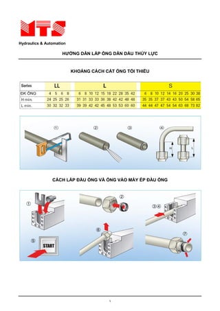
  • 1. Hydraulics & Automation HƯỚNG DẪN LẮP ỐNG DẪN DẦU THỦY LỰC KHOẢNG CÁCH CẮT ỐNG TỐI THIỂU B 2 B 3 CÁCH LẮP ĐẦU ỐNG VÀ ỐNG VÀO MÁY ÉP ĐẦU ỐNG B 4 B 5 1
  • 2. Hydraulics & Automation HƯỚNG DẪN LẮP ỐNG DẪN DẦU THỦY LỰC CÁCH LẮP ỐNG CỨNG BẰNG TAY B 6 B 7 CÁCH THÁO ĐẦU ỐNG BẰNG CHÌA VẶN B 8 B 9 2
  • 3. Hydraulics & Automation HƯỚNG DẪN LẮP ỐNG DẪN DẦU THỦY LỰC CÁCH LẮP ĐẦU ỐNG BẰNG HÀN B 0 1 B 1 CÁCH LẮP ĐẦU ỐNG ÉP LOE B 2 1 B 3 1 3
  • 4. Hydraulics & Automation HƯỚNG DẪN LẮP ỐNG DẪN DẦU THỦY LỰC SAI B 4 1 ĐÚNG B 5 1 B 6 1 4
  • 5. Hydraulics & Automation HƯỚNG DẪN LẮP ỐNG DẪN DẦU THỦY LỰC SAI B 7 1 ĐÚNG B 8 1 B 9 1 5
  • 6. Hydraulics & Automation HƯỚNG DẪN LẮP ỐNG DẪN DẦU THỦY LỰC BÁN KÍNH UỐN ỐNG MỀM B 0 2 B 1 2 B 2 6
  • 7. Hydraulics & Automation HƯỚNG DẪN LẮP ỐNG DẪN DẦU THỦY LỰC 1 – ĐỦ KHÔNG GIAN CHO ỐNG CO GIÃN KHI CHỊU ÁP LỰC B 0 B 3 2 SAI ĐÚNG 2 - ĐỦ KHOẢNG CÁCH CẦN THIẾT ĐỂ ỐNG KHÔNG BỊ CĂNG B 1 B 4 2 SAI ĐÚNG 7
  • 8. Hydraulics & Automation HƯỚNG DẪN LẮP ỐNG DẪN DẦU THỦY LỰC 3 – SỬ DỤNG ĐẦU NỐI ĐỂ ỐNG CÓ CHIỀU DÀI NGẮN NHẤT B 5 2 B 6 2 SAI ĐÚNG 4 – TRÁNH ĐỂ ỐNG LÀM VIỆC TRÊN HAI MẶT PHẲNG B 7 2 B 8 2 SAI ĐÚNG 8
  • 9. Hydraulics & Automation HƯỚNG DẪN LẮP ỐNG DẪN DẦU THỦY LỰC 5 – SỬ DỤNG ĐẦU NỐI GÓC CHO SỐ GÓC UỐN ÍT NHẤT B 9 2 B 0 3 ĐÚNG SAI 6 – TRÁNH ĐỂ ỐNG BỊ VẶN XOẮN KHI CHUYỂN ĐỘNG B 1 3 B 2 3 ĐÚNG SAI 9
  • 10. Hydraulics & Automation HƯỚNG DẪN LẮP ỐNG DẪN DẦU THỦY LỰC 7 – SỬ DỤNG ĐẦU NỐI CHUYỂN ÍT NHẤT ĐỂ TRÁNH RÒ RỈ B 3 B 4 3 SAI ĐÚNG 8 – SỬ DỤNG ĐẦU NỐI 45, 90ĐỂ THU GỌN KHÔNG GIAN ĐI ỐNG B 5 3 B 6 3 SAI ĐÚNG 10
  • 11. Hydraulics & Automation HƯỚNG DẪN LẮP ỐNG DẪN DẦU THỦY LỰC 9 – ĐỂ KHÔNG GIAN CO GIÃN ỐNG KHI CHỊU ÁP B 7 3 B 8 3 10 – KHÔNG ĐỂ ỐNG BỊ VẶN XOẮN KHI LẮP ỐNG B 9 3 B 0 4 ĐÚNG SAI 11 – SỬ DỤNG ỐNG BỌC,KẸP CÁCH LY ỐNG VỚI ỐNG CÓ NHIỆT ĐỘ CAO B 1 4 11
  • 12. Hydraulics & Automation HƯỚNG DẪN LẮP ỐNG DẪN DẦU THỦY LỰC B 2 4 SAI ĐÚNG 12 – SỬ DỤNG CO 90 ĐỂ DỄ BẢO DƯỠNG, THÁO LẮP, KHÔNG GIAN GỌN GÀNG B 3 4 B 4 ĐÚNG SAI 12
  • 13. Hydraulics & Automation HƯỚNG DẪN LẮP ỐNG DẪN DẦU THỦY LỰC 13 – KHÔNG ĐỂ ỐNG CÓ BÁN KÍNH UỐN QUÁ NHỎ SO VỚI BÁN KÍNH TỐI THIỂU B 5 4 B 6 4 SAI ĐÚNG 14 – TRÁNH ỐNG CỌ XÁT VÀO VẬT CỨNG KHI CHUYỂN ĐỘNG B 7 4 B 8 4 SAI ĐÚNG 13
  • 14. GENERAL INFORMATION • STEEL USED ON ALL SERIES Carbon steel fittings Component Material specification Reference norm CF9SMnPb36 CF9SMnPb28 CF9SMn36 CF9SMn28 UNI 4838 Ring / sleeve 11SMnPb37 11SMnPb30 11SMn37 11SMn30 EN 10087 CF9SMnPb36 CF9SMnPb28 CF9SMn36 CF9SMn28 UNI 4838 Nut 11SMnPb37 11SMnPb30 11SMn37 11SMn30 EN 10087 CF9SMnPb36 CF9SMnPb28 CF9SMn36 CF9SMn28 UNI 4838 Straight body 11SMnPb37 11SMnPb30 11SMn37 11SMn30 EN 10087 CF9SMnPb36 CF9SMnPb28 CF9SMn36 CF9SMn28 UNI 4838 Forged body 11SMnPb37 11SMnPb30 11SMn37 11SMn30 EN 10087 Stainless steel fittings Component Material specification Reference norm DIN 17440 Ring / sleeve X6CrNiMoTi17-12-2 (1.4571) X5CrNiMo17-12-2 (1.4401) EN 10088 DIN 17440 Nut X6CrNiMoTi17-12-2 (1.4571) X2CrNiMo17-12-2 (1.4404) EN 10088 DIN 17440 Straight body X6CrNiMoTi17-12-2 (1.4571) X5CrNiMo17-12-2 (1.4401) EN 10088 DIN 17440 Forged body X6CrNiMoTi17-12-2 (1.4571) X5CrNiMo17-12-2 (1.4401) EN 10088 • ALLOWED WORKING TEMPERATURES Carbon Steel -20° to + 120° degrees Celsius, according to ISO 8434 Stainless steel -60° to + 200° degrees Celsius, according to ISO 8434 • PRESSURE RATE REDUCTION The allowed working pressure for stainless steel fittings manufactured with 1.4571 must be reduced accor- ding to the working registered temperature as per ISO 8434. In case of multi-components systems all the parameters must be calculated on the weakest component used. Type of steel Working temperature Lowering percentage 1.4571 ≥ 50°C - 4% 1.4571 ≥ 100°C - 11% 1.4571 ≥ 200°C - 20% • GASKETS The gaskets used on valves and fittings are normally manufactured in NBR. All have a working temperature of -35° to +100° degrees Celsius with a hardness of 85 ± 5 shores. For higher temperatures Viton® seals are suggested with working temperatures between -25° to + 200° degrees Celsius with a hardness of 80 ± 5 shores. All the items that are assembled with gaskets or seals of any kind must be handled according to the DIN 7716 norm (requisites for the stocking of rubber product). • SEAL ON THREADED ENDS To obtain the maximum performance, the taper male thread is to be matched with the taper female thread. The cylindrical male thread is to be matched with the cylindrical female thread. It is possible to match a taper male thread with a cylindrical female thread, but this combination is technically valid only in pipings where medium/low performances are required and is never to be used where high pressures are applied. In case of matching of a cylindrical thread with relatively soft material, it is advisable to use the plain gasket type of seal that guarantees a perfect sealing even with a relatively low tightening torque. VITON® is a DuPont Dow Elastomers Trade Mark 12
  • 15. • CARBON STEEL FITTINGS FINISH TREATMENT All fittings and valves are zinc-plated according to UNI ISO 2081 and 4520. The parts after treatment appear white with yellow shades of color. The plating thickness is 8 ÷ 12 microns. This new treatment fully comply to the latest EEC environmental directives as its hexavalent chromium free. The resistance in saline fog with standard salt concentration ( test in accordance with UNI ISO 9227 ) is 400 hours before the protective layer begins to wear off. Additionally, this treatment, chemically lubricate the items reducing as well torque strength requirements. Due to this treatment the parts may be used also in external exposure provided that the environment be not very aggressive. The cutting ring, after heat treatment to harden the surface, passi- vation treatment and ecological zinc-plating, follows a bath which facilitates the assembly. • STAINLESS STEEL FITTINGS FINISH TREATMENT All the fittings and valves are treated with a chemical cleaning process which eliminate all oxides and burrs due to the machining phase, without altering or damaging the product. After this, follows a bath to clean the product and take away the last impurities, if any. The piece at the end of the treatment looks real bright, very indicated for industrial applications where this type of steel is normally requested. • THERMAL TREATMENT The cutting rings after being machined are heat treated to harden the surface. This type of treatment, on stainless steel cutting rings, may decrease the amagneticity of the ring itself. STAINLESS STEEL FITTINGS ANTI-SEIZING COMPOUND (NICKEL BASIS) Seen the special characteristics of this type of The anti-seizing compound (Nickel Basis) exposed steel (hard but mild) particular attentions are to a strong pressure originates "millions of grains required to avoid problems. One of these require- of Nickel" rolling between the surfaces. It allows a ments is the correct lubrication of all the compo- safer tightening and an easier unblocking. This nents to be done during pre-assembling and compound may be used both indoors and out- assembling. Therefore is required to use the right doors. It protects the threads from wearing out and lubricant to make properly functional systems, at breaking, keeps away rust and corrosion. Nickel all times. covers the connected surfaces avoiding any foun- ding or welding and moreover there is only pure colloidal nickel and no trace of carbonic deposits. According to specification Mil. A 907 D. Approved by the Ministry of Agriculture of the Uni- ted States of America (USAD). Packaging weight 227 gr. Art. 82356. N.B.: Do not use on systems with oxygen or in the presence of ammonia or acetylene. 13
  • 16. • ALLOWED CARBON STEEL TUBES ON ALL SERIES • For steel tubes in mild carbon steel we advise to use calibrated seamless cold drawn without welding tubes ST 37.4 as per DIN 1630. • Maximum allowed hardness on the outside diameter of the tube is 75 HRB. • The indicated pressure are to be intended at a constant pressure rate and with temperatures between -20° and +120° degrees Celsius. Static Dinamic Static Dinamic ØTube Tolerance Thickness DIN 2413-I DIN 2413-III Weight ØTube Tolerance Thickness DIN 2413-I DIN 2413-III Weight mm mm mm pressure pressure Kg/m mm mm mm pressure pressure Kg/m bar bar bar bar 4 ±0,1 0,5 313 274 0,047 18 ±0,08 2 313 274 0,789 4 1 522 502 0,075 18 ±0,8 2,5 392 335 0,956 6 1 389 374 0,123 18 3 409 393 1,111 6 ±0,1 1,5 549 528 0,166 20 ±0,08 2** 282 249 0,888 6 2 692 665 0,197 20 2,5 353 305 1,079 8 1 333 289 0,222 20 ±0,8 3 373 358 1,258 8 1,5 431 441 0,240 20 3,5 426 410 1,424 ±0,1 8 2 549 528 0,296 20 4 478 460 1,578 8 2,5 658 632 0,339 22 2* 256 228 0,986 10 1 282 249 0,222 22 ±0,8 2,5 320 280 1,202 10 1,5 373 358 0,314 22 3 385 329 1,406 10 ±0,1 2 478 460 0,395 25 2* 226 202 1,134 10 2,5 576 553 0,462 25 2,5 282 249 1,387 10 3 666 641 0,518 25 ±0,08 3 338 294 1,628 12 1* 235 210 0,271 25 4 394 379 2,072 12 1,5 353 305 0,388 25 4,5 437 420 2,275 12 2 409 393 0,493 28 2* 201 182 1,282 ±0,08 12 2,5 495 476 0,586 28 ±0,08 2,5 252 224 1,572 12 3 576 553 0,666 28 3 302 265 1,850 12 3,5 651 627 0,734 30 2** 168 171 1,381 14 1,5 302 265 0,462 30 2,5 235 210 1,695 ±0,08 14 2 403 343 0,592 30 3 282 249 1,998 14 ±0,08 2,5 434 417 0,709 30 4 376 323 2,565 14 3 507 487 0,814 35 2* 161 147 2,189 14 3,5 576 553 0,906 35 ±0,15 2,5 201 182 2,004 15 1,5 282 249 0,499 35 3 242 216 2,367 15 ±0,08 2 376 323 0,641 35 4 322 281 3,058 15 3 478 460 0,888 38 ± 3** 223 200 2,589 16 1,5** 264 234 0,536 38 ±0,15 4 297 261 3,354 16 2 353 305 0,691 38 5 371 319 4,069 ±0,08 16 2,5 386 372 0,832 42 3 201 182 2,885 ±0,2 16 3 452 435 0,962 42 4 269 238 3,749 18 ±0,08 1,5* 235 210 0,610 * Tubes that require support sleeve if used for DIN 2353 applications ** Tubes to be used for ISO 8434-2 / SAE J514 norm only CALCULATION PRESSURES The calculation of pressure with static load is made to DIN 2413-I with yield point K=235N/mm2. For tubes with external/internal diameter ratio >1.35 calculation is made to DIN 2413-III but with yield point K=235N/mm2. The calculation of pressures with dynamic stress is made to DIN 2413-III with permanent fatigue strength K=226N/mm2. Safety factor S=1.5. Allowance factor c=0.8 for diameter tube 4mm, c=0.85 for diameter tube 6-8mm, c=0.9 for diameter tube >8mm. Corrosion: additional allowance are not considered for calculation of pressures. 14
  • 17. • ALLOWED STAINLESS STEEL TUBES ON ALL SERIES • For steel tubes in stainless steel we advise to use calibrated seamless cold drawn without welding tubes 1.4571 as per DIN 17458 or ASTM A269. • Maximum allowed hardness on the outside diameter of the tube is 85 HRB. • The indicated pressure are to be intended on a constant pressure rate and with temperatures between -60° and +200° degrees Celsius. Static Static ØTube Tolerance Thickness DIN 2413-I Weight ØTube Tolerance Spessore DIN 2413-I Weight mm mm mm pressure Kg/m mm mm mm pressure Kg/m bar bar 4 ±0,1 ±0,1 0,5 326 0,048 18 2 326 0,801 4 1 544 0,076 18 ±0,8 2,5 409 0,971 6 1 406 0,125 18 3 426 1,128 6 ±0,1 1,5 572 0,169 20 2** 294 0,902 6 2 721 0,200 20 2,5 368 1,095 8 1 347 0,225 20 ±0,8 3 389 1,277 8 1,5 449 0,244 20 3,5 444 1,446 ±0,1 8 2 572 0,301 20 4 498 1,602 8 2,5 686 0,344 22 2* 267 1,001 10 1 294 0,225 22 ±0,8 2,5 334 1,220 10 1,5 389 0,319 22 3 401 1,427 10 ±0,1 2 498 0,401 25 2* 236 1,151 10 2,5 601 0,469 25 2,5 294 1,408 10 3 694 0,526 25 ±0,08 3 352 1,653 12 1* 245 0,275 25 4 411 2,104 12 1,5 368 0,394 25 4,5 456 2,310 12 2 426 0,500 28 2* 210 1,301 ±0,08 12 2,5 516 0,595 28 ±0,08 2,5 263 1,596 12 3 601 0,676 28 3 315 1,878 12 3,5 679 0,745 30 2** 175 1,402 14 1,5 315 0,469 30 2,5 245 1,721 ±0,08 14 2 420 0,601 30 3 294 2,028 14 ±0,08 2,5 452 0,720 30 4 392 2,604 14 3 529 0,826 35 2* 168 2,222 14 3,5 601 0,920 35 2,5 210 2,034 ±0,15 15 1,5 294 0,507 35 3 252 2,403 15 ±0,08 2 392 0,651 35 4 336 3,104 15 3 498 0,902 38 3** 232 2,628 16 1,5** 275 0,544 38 ±0,15 4 310 3,405 16 ±0,08 2 368 0,702 38 5 387 4,131 16 2,5 402 0,845 42 3 210 2,929 ±0,2 16 3 471 0,977 42 4 280 3,806 18 ±0,08 1,5* 245 0,619 * Tubes that require support sleeve if used for DIN 2353 applications ** Tubes to be used for ISO 8434-2 / SAE J514 norm only CALCULATION PRESSURES The calculation of pressure with static load is made to DIN 2413-I with yield point K=245N/mm2. For tubes with external/internal diameter ratio >1.35 calculation is made to DIN 2413-III but with yield point K=245N/mm2. Pressures with dynamic stress according to DIN 2413-III are not listed because in DIN 17458 the permanent fatigue stress K is also not listed. We recommend for calculation in accordance to DIN 2413 III to assume a value K=190N/mm2. Safety factor S=1.5, Allowance factor c=0.9. Corrosion: additional allowance are not considered for calculation of pressures. • The not sufficient thickness of the tube walls, or the too low longitudinal resistance of the tubes ( particularly mild soft steel ) may create problems of the cutting ring with the according losses of seals and the drastical decrease of safety factor. While choosing the tube this aspect must be considerate. Is good rule to pick tubes so that the internal flare ( decreasing of the internal diameter ) do not exceed the 3/10 of a millimeter up to outside diameter of 16mm and 4/10 of a millimeter on higher diameters. 15
  • 18. • COMPATIBLE FLUIDS TABLE The following table resumes, according to the compatibility with the used fluid, the best possible choice as com- bination between the fitting type of steel ( carbon or stainless steel ), material of the elastomeric seal ( NBR or Viton® ) and type of sealing ( plain metal to metal or metal plus elastomeric sealing). Fluid Carbon Stainless NBR VITON® steel steel Acetiylen • • • • Aceton • • • • Hidrocloric Acid • • • • Phosphoric Acid • • • • Nitrico Acid • • • • Solforic Acid • • • • Water • • • • Distilled water • • • • Sea water • • • • Hidrogen peroxide • • • • Turpentine • • • • Ammonia gas, cold • • • • Ammonia liquid • • • • Carbonic dioxide • • • • Argon • • • • Air • • • • Compressed air • • • • ASTM-Oil, n°1 • • • • ASTM-Oil, n°2 • • • • ASTM-Oil, n°3 • • • • Nitrogen • • • • Benzene • • • • Sulfur oxide • • • • Carbon bisolfure • • • • Butane • • • • Clorine • • • • Helium • • • • Etane • • • • Ether • • • • Combustibile gas • • • • Natural gas • • • • Natural gas untreated • • • • Diesel fuel • • • • Glycerin • • • • Glycol • • • • Hidrogen • • • • Iodine • • • • Kerosene • • • • Methane • • • • Methanol • • • • Fuel oil • • • • 16
  • 19. Fluid Carbon Stainless NBR VITON® steel steel Neon • • • • Oil • • • • Heating fuel oil • • • • Automotive brake fluid • • • • Transmission fluid • • • • Mineral oil • • • • Natural mineral oil • • • • Hydraulic oil • • • • Vegetable oil • • • • Carboni monoxide • • • • Oxygen • • • • Ozone • • • • Pentane • • • • Pentane liquid • • • • Propane • • • • Silicone • • • • Styrol • • • • Toluol • • • • Trichloroethylene • • • • Steam • • • • Xylol • • • • Legenda • = Sufficient • = Scarce • = Not recommended • = Not sufficient data VITON® is a DuPont Dow Elastomers Trade Mark 17
  • 20. PRESCRIPTIONS TO COMPLY WITH ON ALL SERIES • Use only CAST S.p.A. components for the same assembly • Apply completely the General Instructions, Utilization Norms, Safety Factors, Assembly Instruction and Working Pressures for the specific fitting is used. • Respect the working temperature rates and temperature related pressure rate reduction, if any. • Respect the indicated tightening values as well as the assembly instructions. • Lubricate all the components, as indicated in the assembly instructions, with specific products. • All tubes must be properly pre-assembled or flared before being assembled on machine board. Is not allowed to pre-assemble directly on machine board. • All stainless steel parts must be assembled on hardened tools and all stainless steel tubes must be pro- perly pre-assembled or flared before being assembled on machine board. Is not allowed to preassemble directly on machine board. • Use only high quality carbon and stainless steel tubes as per our indication on pages 14 and 15. • Use support sleeves on thin tubes. • Is not allowed to mix different materials ( carbon and stainless steel ) in the same connection. • Always check the correct alignment of the system. • Always check the correct incision of the cutting ring on the tube. • Is not allowed, in any case, to use non conform tubes or fittings, as well as is not allowed to make non conform assembly. • Is not allowed to alter in any way CAST S.p.A. products. • Fully comply to all technical information indicated in this catalogue. • In case of doubt always refer to the prudence concept. Not following any of these prescription may alter greatly the functionality of the products causing problems to the system, and the immediate loss of all products guarantees. • PRODUCT LIABILITY 73. D.P.R. 224-CEE 85/347 states that " ... the responsibility will be charged to the negligent part ... " This means that the manufacturer will be held responsible if, and only if, the product was effectively faulty. The distributor that has done the final sale shall check, under its own responsibility, that its final customer was well aware of all technical problems inherent to the product used such as assembly instructions, and that the product was used for the right application. On the same line the end user will be considered responsible part if did not follow completely the written prescriptions of the manufacturer ( General Catalogue ) that must be notified to him by the part doing the sale. Should the end user be short of this technical documentation CAST S.p.A. will be glad to send it direc- tly. In view of this European norm CAST S.p.A. declines any responsibility in the case which the user fails to comply strictly and entirely with the General Instruction, Utilization Norms, Safety Factors, Assembly Instruction and Working Pressures as any other technical information clearly indicated in this General Cata- logue as failure to these prescriptions may affect the functional safety of the products and results in voiding the user's warranty rights. As per the quoted norm there is a 500,00 franchise. 18
  • 21. B3 B3 STANDARD DOUBLE CUTTING EDGE RING ASSEMBLED ON ALL CAST PRODUCTION ASSURES SEALING AND SAFETY AVAILABLE IN CARBON AND STAINLESS STEEL 19
  • 22. B3 THEORY OF OPERATION The Cast fitting, manufactured according to ISO 8434-1/DIN 2353 norm is a mechanical fitting with a dou- ble cutting ring for double stapling on the tube. The ring helps fast assembly of removable tubes, avoids welding, tapping and flaring, thus assuring maxi- mum simplicity of complex oleo-dynamic systems. During tightening by the nut, the ring deforms according to the bore of the 24° cone of the fitting and bites into the steel tube, producing two deep cuts the first of which is visible due to lifting of an outer edge on the diameter of the tube, allows the water tightness and anti-unthreading of the ring. The second groove (invisi- ble) balances the forces on the whole ring, prevents vibrations to reach the first groove and stops the sta- pling of the tube at a predetermined value. COUPLING Reference SYSTEM prescriptions: DIN 2353 ST 37.4 tube DIN 1630-2391 Nut DIN 3870 Cutting ring DIN 3861-B Traceability Shape of housing decoding DIN 3861 = Manufacturer •T= Production plant Fitting body DIN 3901 •0= Year manufactured • CE = Made in EEC • 38 = Metal to metal seal Type of steel DIN 3852-1B/2B used • 01 = Heat number of Threaded end the steel used DIN 3852 20
  • 23. B3 TECHNICAL CHARACTERISTICS The Cast fitting assures a perfect seal, independently from the fluid used, provided that no corrosive fluids be employed and the nominal pressures not be trespassed. Fittings are manufactured in three ranges to be chosen according to the required working conditions. "LL" extra light range, suitable for low and medium working pressures up to 100 bar. "L" light range, suitable for medium/high pressure applications, however not over 315 bar. "S" heavy range, for severe conditions, with high pressures, water hammering, high temperatures and a maximum pressure of 630 bar. Vibrations according to the standards, don't change the fitting's performance that, even at maximum values keeps its characteristics of absolute reliability. Before assembly on the metal tube After assembly on the metal tube 3 1 2 Field of force after assembly Pressure surfaces after assembly Sealing points 1-2-3 21
  • 24. B3 DETAIL OF B3 CUTTING RING SEALING POINTS Cutting ring: 100110 Tube: Ø22x1,5 Cutting ring assembly: one full turn on fitting body as per DIN 3859-2 norm Magnifying: Microscope x5 Detail scale: 0,5 SEALING POINT 1 – FIRST CUTTING EDGE SEALING POINT 2 – SECOND CUTTING EDGE SEALING POINT 3 – 24° CONE 22
  • 25. B4 B4 NEW SIX-SEALS CUTTING RING. INTERNATIONAL INDUSTRIAL PATENT Nr. 864061 of the 10/03/99 FLANKS AND DOES NOT REPLACE THE STANDARD RING CURRENTLY IN USE AVAILABLE IN CARBON AND STAINLESS STEEL 23
  • 26. B4 THEORY OF OPERATION The “B4” is a highly innovative, deformable, double clinching, double edge ring with double elastomer seal that is assembled according to well-known techniques and is perfectly interchangeable with all types of rings used on 24° cone fittings complying with the ISO 8434-1/DIN 2353 standards. The ring helps fast assembly of removable tubes, avoids welding, tapping and flaring, thus assuring maxi- mum simplicity of complex oleo-dynamic systems. During tightening by the nut, the ring deforms according to the bore of the 24° cone of the fitting and bites into the steel tube, producing two deep cuts the first of which is visible due to lifting of an outer edge on the diameter of the tube, allows the water tightness and anti-unthreading of the ring. The second groove (invisi- ble) balances the forces on the whole ring, prevents vibrations to reach the first groove and stops the sta- pling of the tube at a predetermined value. COUPLING Reference SYSTEM prescriptions: DIN 2353 ST 37.4 tube DIN 1630-2391 Nut DIN 3870 O-Ring Cutting ring DIN 3861-B Flat washer seal Traceability Shape of housing decoding DIN 3861 = Manufacturer •T= Production plant Fitting body DIN 3901 •0= Year manufactured Flat • CE = washer housing Made in EEC DIN 3852-11E • 38 = Type of steel used • 01 = Heat number of Threaded end the steel used DIN 3852 24
  • 27. B4 TECHNICAL CHARACTERISTICS The “B4” ring assures perfect tightness of the circuit regardless of the fluid used provided that corrosive fluids are avoided and the nominal pressures of the fittings are complied with. The fittings on which the “B4” rings are mounted are manufactured in two series that are used according to the operating conditions. “L” light duty series for applications characterized by medium high pressures, maximum 315 bar. “S” heavy duty series for harsh applications characterized by high temperatures and a maximum pressure of 630 bar. “B4” performance is not affected by vibrations within normal limits and the product maintains its optimal characteristics, as an absolutely safe ring, even at maximum values. When the fitting, ring, nut, tube system is assembled, the flat seal is compressed between the head of the cutting ring and the front of the fitting body. The mechanical pressure applied to the flat seal causes flexure towards the outside, with a consequent increase in diameter. The deformation causes the compressed material of the seal to fill the turns of the thread of the nut free from the closing coupling with the fitting body, assuring locking of the nut and preventing any vibration-induced loosening of this. When the fitting is disassembled the flat seal goes back to its original shape, without any damage, freeing the nut threads. Before assembly on the metal tube After assembly on the metal tube 6 5 3 1 2 4 Field of force after assembly Pressure surfaces after assembly Sealing points 1-2-3-4-5-6 25
  • 28. B4 109. DETAIL OF B4 CUTTING RING SEALING POINTS Cutting ring: 100110.4 Tube: Ø22x1,5 Cutting ring assembly: one full turn on fitting body as per DIN 3859-2 norm Magnifying: Microscope x5 Detail scale: 0,5 SEALING POINT 1 SEALING POINT 4 FIRST CUTTING EDGE O-RING SEALING POINT 2 SEALING POINT 5 SECOND CUTTING EDGE FLAT WASHER SEAL ON FITTING BODY SEALING POINT 3 SEALING POINT 6 24° CONE FLAT WASHER SEAL IN NUT THREADS 26
  • 29. B4 TECHNICAL INNOVATION For many years now, there has been an increasing imperative market demand for fluid system components able to guarantee three main factors: safety, easy assembly, leakage-free tightness. These elements, now considered essential for safety of the working environment (Law 626/94), product lia- bility (Presidential Decree 224-EEC 85/374) and for the entire environmental protection system have promo- ted the development of the new “B4” ring as an effective response to all the above-mentioned problems. PRODUCT CONCEPT The most original aspect of the product is that the structure of the existing ring has been used, inserting an O-Ring in the inside part to obtain another seal on the tube used and a flat seal on the outer diameter to obtain two additional seals. The main idea behind the development of the “B4” was to design a new cutting ring able to go one step beyond the known techniques and to solve the problem of minor losses of tightness, leaks, sweating and loosening of the system fastening nut. With this new ring, the double clinching of the steel tube is still possible and as well as, for obvious rea- sons of safety, the visual inspection of correct coupling between the ring and the steel tube, maintaining the current, perfectly functional system of assembly that is widely known to product users. SEALING “B4” solves the problem of absolute tightness in the following way: • On the outer diameter of the steel tube, with the double cutting edges and with an O-Ring placed inside the ring that provides a first seal with an elastomeric material that didn’t exist before. • In the 24° cone of the fitting body, with an increase in the metal-on-metal contact area and with a flat seal, placed statically on the outer diameter of the cutting ring which, when compressed between the head of the ring and the front of the fitting body, provides a second seal with an elastomeric material that didn’t exist before. • In the thread of the system fastening nut, with the flat seal. When this is compressed between the head of the ring and the front of the fitting body, it fills the threads of the nut that are not engaged in clinching of the coupling system, thus providing a third seal with an elastomeric material that didn’t exist before. • Basically, the “B4” provides six points of seal of which three metal to metal and three by means of two soft elastomeric seals (the flat seal assures two sealing points) thus obtaining a product able to assure complete tightness without any possibility of leakage even in particularly harsh operating conditions. 27
  • 30. B3-B4 GENERAL INSTRUCTIONS FOR B3 AND B4 RINGS • Before starting the preassembly make sure that the pierce of the machine and the hardened blocks are in perfect working order. Further inspections are necessary during the preassembly (every 30-50 tightenings). For this purpose we advise to use a control buffer 1000… pierce and replace any block out of tolerance. • Over the whole tightening phase the tube must be in touch with the inner part of the body of the fitting. If this does not happen, the ring will advance with the tube without indenting it, so the coupling would not be functional and it would be necessary to do the operation again. The tube must not turn with the nut during the tightening phase; the capability of the ring to rotate, once the pre-assembly is done, is not a deficiency but is a consequence of the right elasticity of the ring. Always check that the tube be correctly indented. If the indentation does not cover 80% of the ring front side then the assembly is not functional and must be done again. Indicated pressures are for steel tubes only. • In case thin wall tubes are used, specially mild tubes, or tubes in Rilsan or similar, the assembling is pos- sible, but a suitable reinforcement must be inserted into the end of the tube that is going to be tightened. Without the reinforcement it is not possible to operate with the above mentioned materials. • Before assembling the preassembled tube to the equipment it is necessary to check that the tube and the fitting are aligned. Fitting should never be used to correct a wrong alignment or to be a support for the tube. Extremely long tubes or tubes undergoing high stress have absolutely to be fixed by using some support to avoid excessive vibrations that could cause damage to the system. • The proper lubrication of components involved in the tightening is basic for good working. We advise to use mineral oils for carbon steel fittings and anti-seizing compound (Nickel basis) for Stain- less steel fittings. • The fittings and the valves in this technical catalogue may the used for fluido-dynamic connections only. • Is not allowed to mix carbon and stainless steel components. UTILIZATION STANDARDS FOR B3 AND B4 CUTTING RINGS CARBON STEEL FITTINGS • High quality tubes must be employed to assure correct use and related technical performance of carbon steel fitting. Use of tubes without the aforementioned characteristics may seriously impair the efficiency of the fitting. We recommend use of the following tubes only: ST 37.4 steel seamless tubes complying with DIN 1630, inner and outer diameter tolerances as per DIN 2391, maximum permissible hardness, measured on the outer diameter of the tube is 75 HRB. • All carbon steel tubes with a diameter of more than 10 mm must be pre-assembled using the specific preassembly machine. If this is not available, hardened blocks, to be clamped in vice for manual preassem- bly, must be used. Remember to oil the thread, nut and ring. If hardened pre-assembly blocks are not avai- lable, normal straight fittings can be used. The fitting used once must be replaced at each tightening. During preassembly, pay particular attention to parts such as reducing standpipes and nipples as these are made of raw materials characterized, therefore, by higher resistance compared with the cuts made on annealed tubes. These parts must always be pre-assembled on hardened 24° cones (for all diameters). STAINLESS STEEL FITTINGS • High quality tubes must be employed to assure correct use and related technical performance of stainless steel fitting. Use of tubes without the aforementioned characteristics may seriously impair the efficiency of the fitting. We recommend use of the following tubes only: cold drawn seamless tube 1.4571 as per DIN 17458 or ASTM A 269, maximum permitted hardness, measured on the outer diameter of the tube, measu- red on the outer diameter of the tube is 85 HRB. Electrically welded tubes may be used provided they com- ply with the mechanical tolerances of the aforementioned standards and related hardness values. • All stainless steel tubes must be pre-assembled using the specific preassembly machine. If this is not available, hardened blocks must be used for manual preassembly. In this case, make sure that the bench and vice in which the block is clamped are firmly fastened to prevent any possibility of movement caused by the twisting moment applied to the nut during the preassembly phase. Assembly or preassembly operations directly on the fitting are not allowed. 28
  • 31. B3-B4 QUALITY ASSURANCE ACCORDING TO UNI EN ISO 9001 The Quality Assurance System complies with UNI EN ISO 9001, certificate (N°90/94) issued by the RINA certification authority recognized by IQNET at European level. CAST S.p.A. has also obtained the DVGW product omologation for stainless steel fittings, and DNV product omologation for carbon and stainless steel fittings with B3 and B4 cutting rings. At the customer’s request, our Quality Service will issue certificates of origin for the materials used to manufacture the products delivered. Our Quality Experts are always ready to provide customers with advice, to guide them around our facilities as to provide documentation of the traceability system applied. COMPONENT TESTING In addition to the normal dimensional checks carried out during machining, percentage inspections of the finished product, practical tightness and fatigue tests, coupling tests between the various parts are also car- ried out on CAST fittings. At the customer’s request, our Product Test and Inspection Service issues the certificate of the tests carried out: dimensional and geometrical tests, checking of static seal at low and high pressure, dynamic seal at high pressure (maximum operating pressure + 33%) as per ISO 8434-5. If required by the customer, tests can be carried out by various Third Party Authorities including: RINA – DVGW – Lloyd’s Register of Shipping – Det Norske Veritas – Germanischer Lloyd – American Bureau of Shipping (to be specified on the order). SAFETY FACTORS • B3 and B4 rings provide the right answer to safety problems so that absolute functional reliability between the ring, the steel tube and the fitting body is guaranteed by the double clinching and automatic locking of the cuts on the steel tube (assured by the particular shape of the ring). • CAST’s product range fully complies with the construction parameters of reference standards. • The nominal operating pressures (bar) given in the catalogue indicate the maximum permissible pressures (including pressure peaks). For higher pressure the items must be tested in accordance with the manufac- turer for specific applications. • The safety factor is 4:1 and is intended with static load and with the temperature at the values indicated as per DIN 3861 (24° cone) for tube connection. The same safety factor 4:1 is intended for parallel threaded end fittings with elastomeric seal. For stud couplings with taper or parallel threaded end fittings with metal to metal seal safety factor is 2,5:1. • Is understood that the product is guaranteed only if the full connection is made entirely with CAST S.p.A. products and components. Destructive testing with 28x2 carbon steel tube The tube burst at 650 bar without any leakages or sweating from the sealing points 29
  • 32. B3-B4 STUD ENDS DIN 2353 WITH BSPP THREAD Serie ØTube BSPP D4 min D4 min L1 L2 L Torque (Nm) Torque (Nm) Torque (Nm) Torque (Nm) Thread D3 form B/E form G/H max min rif form B form E form H form G 6 G 1/8 9,8 15 17,2 1 8 7,5 20 20 20 20 8 G 1/4 13,2 20 20,7 1,5 12 10,2 45 45 45 45 10 G 1/4 13,2 20 20,7 1,5 12 10,2 45 45 45 45 12 G 3/8 16,7 23 24,5 2 12 10,4 70 70 70 70 L 15 G 1/2 21 28 29,6 2,5 14 13,1 130 85 85 85 18 G 1/2 21 28 29,6 2,5 14 13,1 130 85 85 85 22 G 3/4 26,5 33 36,9 2,5 16 13,5 170 170 170 170 28 G1 33,3 41 46,1 2,5 18 14,7 330 330 330 330 35 G 1 1/4 42 51 54 2,5 20 14,7 510 430 430 430 42 G 1 1/2 47,9 56 60,5 2,5 22 14,7 600 510 510 510 6 G 1/4 13,2 20 20,7 1,5 12 10,2 55 55 55 55 8 G 1/4 13,2 20 20,7 1,5 12 10,2 55 55 55 55 10 G 3/8 16,7 23 24,5 2 12 10,4 85 80 80 80 12 G 3/8 16,7 23 24,5 2 12 10,4 85 80 80 80 S 14 G 1/2 21 28 29,6 2,5 14 13,1 150 110 110 110 16 G 1/2 21 28 29,6 2,5 14 13,1 150 110 110 110 20 G 3/4 26,5 33 36,9 2,5 16 13,5 280 170 170 170 25 G1 33,3 41 46,1 2,5 18 14,7 330 330 330 330 30 G 1 1/4 42 51 54 2,5 20 14,7 510 430 430 430 38 G 1 1/2 47,9 56 60,5 2,5 22 14,7 680 510 510 510 Performances: Sealing form B: Sealing form E: Sealing form H: Sealing form G: - Pressure capacity Good Excellent Excellent Excellent - Sealing characteristics Good Excellent Excellent Excellent - Additional sealing required no no no no - Safety factor 2,5:1 4:1 4:1 4:1 30 *In revision phase
  • 33. B3-B4 STUD ENDS DIN 2353 WITH METRIC THREAD Serie ØTubo Metric D4 min D4 min L1 L2 L Torque (Nm) Torque (Nm) Torque (Nm) Torque (Nm) Thread D3 form B/E form G/H max min rif form B form E form H form G 6 M10x1 10 15 16 1 8 7,6 20 20 20 20 8 M12x1,5 12 18 19 1,5 12 9,7 30 30 30 30 10 M14x1,5 14 20 21 1,5 12 9,7 45 45 50 50 12 M16x1,5 16 23 24 1,5 12 10,2 60 55 55 55 15 M18x1,5 18 25 26 2 12 10,9 80 70 70 70 L 18 M22x1,5 22 28 29 2,5 14 12 130 120 120 120 22 M26x1,5 26 33 - 2,5 16 - 180 170 - - 22 M27x2 27 33 34 2,5 16 13,8 - - 170 170 28 M33x2 33 41 43 2,5 18 13,8 330 330 330 330 35 M42x2 42 51 52 2,5 20 13,8 470 430 430 430 42 M48x2 48 56 57 2,5 22 15,3 600 510 510 510 6 M12x1,5 12 18 19 1,5 12 9,7 40 40 40 40 8 M14x1,5 14 20 21 1,5 12 9,7 55 55 55 55 10 M16x1,5 16 23 24 1,5 12 10,2 80 70 70 70 12 M18x1,5 18 25 26 2 12 10,9 105 85 85 85 14 M20x1,5 20 27 27 2 14 12 150 120 120 120 S 16 M22x1,5 22 28 29 2,5 14 12 170 130 130 130 20 M27x2 27 33 34 2,5 16 13,8 200 170 170 170 25 M33x2 33 41 43 2,5 18 13,8 390 330 330 330 30 M42x2 42 51 52 2,5 20 13,8 510 430 430 403 38 M48x2 48 56 57 2,5 22 15,3 680 510 510 510 Performances: Sealing form B: Sealing form E: Sealing form H: Sealing form G: - Pressure capacity Good Excellent Excellent Excellent - Sealing characteristics Good Excellent Excellent Excellent - Additional sealing required no no no no - Safety factor 2,5:1 4:1 4:1 4:1 31
  • 34. B3-B4 STUD ENDS DIN 2353 WITH METRIC THREAD (ISO 6149) P max P max Metric Torque (Nm) Torque (Nm) Serie ISO 6149 ISO 6149 ØTube D2 D5 L1 L3 L4 L Z° ISO 6149 ISO 6149 STRAIGHT ADJUSTABLE Thread min max min rif STRAIGHT ADJUSTABLE 315 315 6 M10x1 16 11,1 1,6 1 10 8,6 12 15 15 315 315 8 M12x1,5 19 13,8 2,4 1,5 11,5 11,1 15 25 25 315 315 10 M14x1,5 21 15,8 2,4 1,5 11,5 11,1 15 30 30 315 250 12 M16x1,5 24 17,8 2,4 1,5 13 11,6 15 35 35 L 315 250 15 M18x1,5 26 19,8 2,4 2 14,5 12,3 15 40 40 315 250 18 M22x1,5 29 23,8 2,4 2 15,5 13,4 15 55 55 160 160 22 M27x2 34 29,4 3,1 2 19 15,8 15 85 85 160 160 28 M33x2 43 35,4 3,1 2,5 19 15,8 15 140 140 160 160 35 M42x2 52 44,4 3,1 2,5 19,5 15,8 15 180 180 160 160 42 M48x2 57 50,4 3,1 2,5 22 17,3 15 230 230 630 400 6 M12x1,5 19 13,8 2,4 1,5 11,5 11,1 15 30 30 630 400 8 M14x1,5 21 15,8 2,4 1,5 11,5 11,1 15 40 40 630 400 10 M16x1,5 24 17,8 2,4 1,5 13 11,6 15 50 50 630 400 12 M18x1,5 26 19,8 2,4 2 14,5 12,3 15 60 60 400 400 14 M20x1,5 27 21,8 2,4 2 14,5 13,4 15 70 70 S 400 400 16 M22x1,5 29 23,8 2,4 2 15,5 13,4 15 85 85 400 400 20 M27x2 34 29,4 3,1 2 19 15,8 15 150 150 400 315 25 M33x2 43 35,4 3,1 2,5 19 15,8 15 260 260 250 250 30 M42x2 52 44,4 3,1 2,5 19,5 15,8 15 280 280 250 200 38 M48x2 57 50,4 3,1 2,5 22 17,3 15 360 360 Performances: STRAIGHT sealing: ADJUSTABLE sealing: - Pressure capacity Excellent Excellent - Sealing characteristics Excellent Excellent - Additional sealing required no no - Safety factor 4:1 4:1 N.B. To obtain the ISO 6149 type of sealing please take out the retaining ring from the standard fitting. 32
  • 35. B3-B4 STUD ENDS DIN 2353 WITH UNF/UN-2A THREAD Serie ØTube UNF/UN-2A D2 L3 L4 L Torque (Nm) Torque (Nm) Thread min D5 L1 max min rif Z° STRAIGHT ADJUSTABLE 6 7/16-20 UNF-2A 21 12,45 2,4 1,6 11,5 9,9 12 20 20 8 1/2-20 UNF-2A 23 14,05 2,4 1,6 11,5 9,9 12 25 25 10 1/2-20 UNF-2A 23 14,05 2,4 1,6 11,5 9,9 12 25 25 12 9/16-18 UNF-2A 25 15,7 2,5 1,6 12,7 11,1 12 30 30 15 3/4-16 UNF-2A 30 20,65 2,5 2,4 14,3 12,5 15 45 45 L 18 3/4-16 UNF-2A 30 20,65 2,5 2,4 14,3 12,5 15 45 45 18 7/8-14 UNF-2A 34 24 2,5 2,4 16,7 14,5 15 55 55 22 1 1/16-12 UN-2A 41 29,2 3,3 2,4 19 16,8 15 85 85 28 1 5/16-12 UN-2A 49 35,55 3,3 3,2 19 16,8 15 130 130 35 1 5/8-12 UN-2A 58 43,55 3,3 3,2 19 16,8 15 170 170 42 1 7/8-12 UN-2A 65 49,9 3,3 3,2 19 16,8 15 180 180 6 1/2-20 UNF-2A 23 14,05 2,4 1,6 11,5 9,9 12 25 25 8 1/2-20 UNF-2A 23 14,05 2,4 1,6 11,5 9,9 12 25 25 10 9/16-18 UNF-2A 25 15,7 2,5 1,6 12,7 11,1 12 35 35 12 9/16-18 UNF-2A 25 15,7 2,5 1,6 12,7 11,1 12 35 35 14 3/4-16 UNF-2A 30 20,65 2,5 2,4 14,3 12,5 15 60 60 S 16 3/4-16 UNF-2A 30 20,65 2,5 2,4 14,3 12,5 15 60 60 16 7/8-14 UNF-2A 34 24 2,5 2,4 16,7 14,5 15 85 85 20 1 1/16-12 UN-2A 41 29,2 3,3 2,4 19 16,8 15 150 150 25 1 5/16-12 UN-2A 49 35,55 3,3 3,2 19 16,8 15 230 230 30 1 5/8-12 UN-2A 58 43,55 3,3 3,2 19 16,8 15 250 250 38 1 7/8-12 UN-2A 65 49,9 3,3 3,2 19 16,8 15 320 320 Performances: STRAIGHT sealing: ADJUSTABLE sealing: - Pressure capacity Excellent Excellent - Sealing characteristics Excellent Excellent - Additional sealing required no no - Safety factor 4:1 4:1 33
  • 36. B3-B4 STUD ENDS DIN 2353 WITH BSPT THREAD STUD ENDS DIN 2353 WITH NPT THREAD Serie ØTube BSPT Serie ØTube NPT Thread L1 L2 Thread L1 6 R 1/8 5,5 9,5 6 1/8-27 NPT 11,6 8 R 1/4 8,5 13,5 8 1/4-18 NPT 16,4 10 R 1/4 8,5 13,5 10 1/4-18 NPT 16,4 12 R 3/8 8,5 13,5 12 3/8-18 NPT 17,4 L 15 R 1/2 10,5 16,5 L 15 1/2-14 NPT 22,6 18 R 1/2 10,5 16,5 18 1/2-14 NPT 22,6 22 R 3/4 13 19 22 3/4-14 NPT 23,1 28 R1 - - 28 1-11,5 NPT 27,8 35 R 1 1/4 - - 35 1 1/4-11,5 NPT 28,3 42 R 1 1/2 - - 42 1 1/2-11,5 NPT 28,3 6 R 1/4 8,5 13,5 6 1/4-18 NPT 16,4 8 R 1/4 8,5 13,5 8 1/4-18 NPT 16,4 10 R 3/8 8,5 13,5 10 3/8-18 NPT 17,4 12 R 3/8 8,5 13,5 12 3/8-18 NPT 17,4 14 R 1/2 10,5 16,5 14 1/2-14 NPT 22,6 S S 16 R 1/2 10,5 16,5 16 1/2-14 NPT 22,6 20 R 3/4 13 19 20 3/4-14 NPT 23,1 25 R1 - - 25 1-11,5 NPT 27,8 30 R 1 1/4 - - 30 1 1/4-11,5 NPT 28,3 38 R 1 1/2 - - 38 1 1/2-11,5 NPT 28,3 Performances: Sealing form C: Performances: Taper sealing: - Pressure capacity Low-Medium - Pressure capacity Low-Medium - Sealing characteristics Low-Medium - Sealing characteristics Low-Medium - Additional sealing required yes - Additional sealing required yes - Safety factor 2,5:1 - Safety factor 2,5:1 34
  • 37. B3-B4 STUD ENDS DIN 2353 WITH METRIC TAPER THREAD Serie Ø Tube Metric Taper Thread L1 L2 6 M10x1 keg 5,5 10 8 M12x1,5 keg 8,5 13,5 L 10 M14x1,5 keg 8,5 13,5 12 M16x1,5 keg 8,5 13,5 15 M18x1,5 keg 8,5 13,5 18 M22x1,5 keg 10,5 15,5 6 M12x1,5 keg 8,5 13,5 8 M14x1,5 keg 8,5 13,5 10 M16x1,5 keg 8,5 13,5 S 12 M18x1,5 keg 8,5 13,5 14 M20x1,5 keg 10,5 15,5 16 M22x1,5 keg 10,5 15,5 Performances: Sealing form C: - Pressure capacity Low-Medium - Sealing characteristics Low-Medium - Additional sealing required yes - Safety factor 2,5:1 35
  • 38. B3-B4 TIGHTENING TORQUES FOR B3 AND B4 CUTTING RINGS DIN 3861 cone for carbon and stainless steel Assembly of B3 Assembly of B4 cutting ring cutting ring Metric Manual Manual Machine Machine Serie ØTube Carbon Stainless Carbon Stainless Thread (Nm) (Nm) (Kg) (Kg) 6 M12x1,5 20 30 1200 1400 8 M14x1,5 25 55 1400 1700 10 M16x1,5 30 85 2000 2200 12 M18x1,5 40 120 2100 2400 15 M22x1,5 60 130 2400 3300 L 18 M26x1,5 90 220 2500 3600 22 M30x2 170 320 2600 3800 28 M36x2 210 500 3000 6900 35 M45x2 360 970 5500 10000 42 M52x2 490 1110 6700 12500 6 M14x1,5 25 45 1200 1400 8 M16x1,5 30 55 1400 1700 10 M18x1,5 40 90 2000 2200 12 M20x1,5 50 105 2100 2400 14 M22x1,5 70 150 2400 3300 S 16 M24x1,5 80 180 2500 3600 20 M30x2 140 340 2600 6400 25 M36x2 230 530 5000 9300 30 M42x2 300 610 5500 10000 38 M52x2 430 850 6700 12500 Notes: All the values reported in the above tightening tables are mere indication, and come from a series of practical tests carried out in the technical laboratory of Volpiano (TO). These may vary accor- ding to the materials and to the tolerances of the employed components. All the values express in Newton Meters (Nm) for the tightening torques on the cone DIN 3861 threads represent the torquing moment necessary to have the correct incision of the pre-assembly of the tube, lifting the required 80% of the front of the edge of the cutting ring. All the values expressed in Kilograms (Kg) for the linear push on the preassembly machine, repre- sent the right strength necessary to have the correct incision of the preassembly lifting the requi- red 80% of the front of the edge of the cutting ring. Once done properly the preassembly and checked that all the components are conforming to the requirements of the system, finish the assembly on the system itself, first closing by wrench until you feel a certain resistance, and then doing the last 1/4 of a turn to close the fitting completely. 36
  • 39. B3-B4 SERIES 60… SWIVEL NUT According to DIN 2353 standards, 24° sealing head as per DIN 2861 and O-Ring seal as per DIN 3865. This series of fittings with revolving nut and seal on the 24° sealing cone guaranteed by an o-ring, meets customers requirements when asking for high pressure, absolute tightness low tightening torque. Because of its technical characteristics this type of fitting is suitable for demanding applications such as assembly on heavy machinery. The result is a safe fastening of the nut to the body impro- ving the whole sealing system. The limit of this series was given by the fact that the preformed sealing with o-ring was limited to a single connection, leaving all the others with the old solutions. A new step forward was needed to improve the research and find a solution that could grant a dou- ble sealing system on all the connections involved, metal to metal plus the elastomeric sealing. This problem has been solved by CAST S.p.A. with the new B4 ring guaranteeing a double sealing, metal to metal plus the elastomeric sealing on all the connections of the fitting. TIGHTENING TORQUES FOR SWIVEL NUT FITTINGS DIN 3861 cone for carbon and stainless steel Serie ØTube Metric Torque Thread (Nm) 6 M12x1,5 20 8 M14x1,5 35 10 M16x1,5 40 12 M18x1,5 45 15 M22x1,5 55 L 18 M26x1,5 110 22 M30x2 130 28 M36x2 200 35 M45x2 220 42 M52x2 240 6 M14x1,5 40 8 M16x1,5 45 10 M18x1,5 50 12 M20x1,5 60 14 M22x1,5 80 S 16 M24x1,5 100 20 M30x2 160 25 M36x2 240 30 M42x2 260 38 M52x2 350 Notes: All the values reported in the above tightening tables and mere indication, and come from a series of practical tests carried out in the technical laboratory of Volpiano (TO). These may vary according to the materials and to the tolerances of the employed components. All the values express in Newton Meters (Nm) for the tightening torques, represent the torquing moment necessary to have the correct tightness. 37
  • 40. B3-B4 DEFINITION OF CONE SIZE TO DIN 3861 STANDARDS THREAD DIAMETERS TO DIN 3853 STANDARDS Allowed for B3 and B4 rings Metric Serie Bar ØTube Thread d1 d2B11 d4+0,1 L3 L8+0,3 4 M8x1 3 4 5 8 4 LL 100 6 M10x1 4,5 6 7,5 8 5,5 8 M12x1,5 6 8 9,5 9 5,5 6 M12x1,5 4 6 8,1 10 7 8 M14x1,5 6 8 10,1 10 7 250 10 M16x1,5 8 10 12,3 11 7 12 M18x1,5 10 12 14,3 11 7 15 M22x1,5 12 15 17,3 12 7 L 18 M26x1,5 15 18 20,3 12 7,5 160 22 M30x2 19 22 24,3 14 7,5 28 M36x2 24 28 30,3 14 7,5 100 35 M45x2 30 35 38 16 10,5 42 M52x2 36 42 45 16 11 6 M14x1,5 4 6 8,1 12 7 8 M16x1,5 5 8 10,1 12 7 630 10 M18x1,5 7 10 12,3 12 7,5 12 M20x1,5 8 12 14,3 12 7,5 14 M22x1,5 10 14 16,3 14 8 S 16 M24x1,5 12 16 18,3 14 8,5 400 20 M30x2 16 20 22,9 16 10,5 25 M36x2 20 25 27,9 18 12 30 M42x2 25 30 33 20 13,5 250 38 M52x2 32 38 41 22 16 38
  • 41. SAE SAE J514 THE CAST 37° STANDARDIZED FITTINGS AN EASY ASSEMBLY A KNOWN PRODUCT, SAFE AND RELIABLE AVAILABLE IN CARBON AND STAINLESS STEEL 39
  • 42. SAE THEORY OF OPERATION The CAST S.p.A. fitting according to the norms ISO 8434-2/ SAE J514, is a mechanical fitting traditionally used for high pressure oleo-dynamic systems. The sealing is made by the contact between two metal surfaces, with no deformation of the single compo- nents. The coupling between the body of the fitting and the flared tube (cone angle 74°) is guaranteed by the tigh- tening nut and by the pressure sleeve on the inside. This allow to realize a fast assembling-disassembling tube making the easiest realization of complex oleo-dynamic systems. COUPLING Reference SYSTEM prescriptions: SAE J514 ST 37.4 tube DIN 1630-2391 Pressure sleeve ISO 8434-2/SAE J514 Nut ISO 8434-2/SAE J514 37° cone Traceability decoding = Manufacturer •T= Production plant •0= Fitting body Year manufactured ISO 8434-2 • CE = Made in EEC Flat washer housing • 38 = ISO 1179-2.2 Type of steel used • 01 = Heat number of Threaded end the steel used ISO 1179-2.2 40
  • 43. SAE TECHNICAL CHARACTERISTICS The CAST S.p.A. 37° fitting grants a perfect sealing of the system independently from the used fluid, as long as corrosive fluids are not used and all the specific prescription for this type of fitting are complied with. These fittings are manufactured in a single series defined “UNIVERSAL” since the body and the nut of the fitting remain the same even when switching from a inches sized tube to a metric tube, and since there are no doubles of diameters with different working pressures. Vibrations, in the norm, do not alter the functionality of this type of fitting, also at the top level of the quoted values, and therefore keeps the best characteristics of absolute guarantee, safety and reliability. For these specific reasons this fitting may be used in hard working conditions. Under the mechanical strength given by the tightening of the nut on the fitting body, the flared 37° part of the tube couples with the conical 37° part of the fitting body giving birth to a metal to metal seal. The pressure sleeve hosted in the inside part of the nut assures the correct alignment of the system dimini- shing the vibrations and avoiding any possible trouble or damaging of the tube during the assembly phase. Before assembly on the metal tube After assembly on the metal tube 1 Field of force after assembly Pressure surfaces after assembly Sealing points 1 41
  • 44. SAE DETAIL 37° CONE SEALING POINTS Tube: Ø25x2 Assembly: as per tightening torque indicated on this catalogue (160Nm) Magnifying: Microscope x5 Detail scale: 0,5 180. SEALING POINT 1 – 37° CONE PRODUCT MATURITY For many years now, there has been an increasing imperative market demand for fluid system components able to guarantee three main factors: safety, easy assembly, leakage-free tightness. These elements, now considered essential for safety of the working environment (Law 626/94), product lia- bility (Presidential Decree 224-EEC 85/374) and for the entire environmental protection system make the 37° flared fitting an effective response to all the above-mentioned problems. Standard SAE J514 fitting with no elastomeric seal available on scheduled orders only. 42
  • 45. SAE SAE J514 THE NEW CAST 37° FITTINGS WITH O-RING A DRY AS THE DUST SEAL AN EASY ASSEMBLY A KNOWN PRODUCT, SAFE AND RELIABLE AVAILABLE IN CARBON AND STAINLESS STEEL 43