1) The document describes an anti-lock braking system (ABS) which uses sensors and controllers to prevent wheels from locking during braking. It aims to allow steering control and minimize stopping distances.
2) The key components of ABS are electronic control units, hydraulic modulators, wheel speed sensors, and a power booster. It monitors wheel speeds and modulates brake pressure to keep wheels rotating just before the lock point.
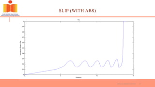
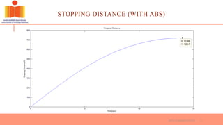
3) Simulation results show ABS is effective, maintaining wheel rotation and reducing vehicle stopping distance compared to conventional braking without ABS. Slip levels are also better controlled with ABS.