Use Case Diagrams|
Unified Modeling
Language (UML)
Rakhi Moni Saha
Lecture
SWE, DIU
2.
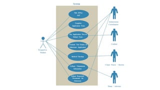
Use Case Diagram
•A Use Case Diagram is a vital tool in system design, it
provides a visual representation of how users interact with a
system.
• It serves as a blueprint for understanding the functional
requirements of a system from a user’s perspective, aiding
in the communication between stakeholders and guiding
the development process.
Use Case DiagramRelationships
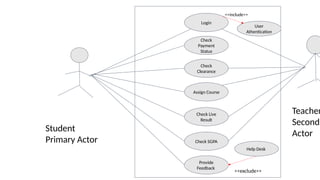
i. Association Relationship
ii. Include Relationship
iii. Extend Relationship
iv. Generalization Relationship
5.
Association Relationship
• TheAssociation Relationship represents a communication or
interaction between an actor and a use case.
• It is depicted by a line connecting the actor to the use case.
• This relationship signifies that the actor is involved in the
functionality described by the use case
6.
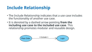
Include Relationship
• TheInclude Relationship indicates that a use case includes
the functionality of another use case.
• It is denoted by a dashed arrow pointing from the
including use case to the included use case. This
relationship promotes modular and reusable design.
7.
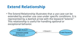
Extend Relationship
• TheExtend Relationship illustrates that a use case can be
extended by another use case under specific conditions. It is
represented by a dashed arrow with the keyword “extend.”
This relationship is useful for handling optional or
exceptional behavior.
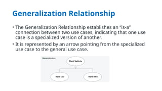
Generalization Relationship
• TheGeneralization Relationship establishes an “is-a”
connection between two use cases, indicating that one use
case is a specialized version of another.
• It is represented by an arrow pointing from the specialized
use case to the general use case.