
Recommended
More Related Content
What's hot
What's hot (20)
Similar to 7 segment display.ppt
Similar to 7 segment display.ppt (20)
Recently uploaded
Recently uploaded (20)
7 segment display.ppt
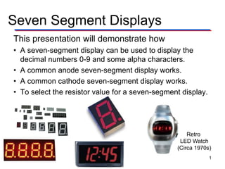
- 1. Seven Segment Displays Retro LED Watch (Circa 1970s) This presentation will demonstrate how • A seven-segment display can be used to display the decimal numbers 0-9 and some alpha characters. • A common anode seven-segment display works. • A common cathode seven-segment display works. • To select the resistor value for a seven-segment display. 1
- 2. Segment Identification • A Seven-Segment Display (SSD) is simply a figure eight grouping of LEDs {some include a decimal point (DP)}. • Each Segment is labeled (a) thru (g). • SSDs are available in two configurations – Common Cathode (all LED cathodes are connected) – Common Anode (all LED anodes are connected) a b c d e g dp f 2
- 3. SSD Display Possibilities Decimal Digits 0-9 Simple Messages Select Alpha Characters 3
- 4. Basic LED Operations To Turn an LED ON . . . • The ANODE must be at a higher voltage potential (1.5v) than the CATHODE. • The amount of current flowing through the LED will determine the brightness of the LED. • The amount of current is controlled by a series resistor. (not shown) To understand how a seven-segment display works, we must review how an LED works. CATHODE (‒) (+) ANODE ← Current Flow 4
- 5. LED Configuration – Anode @ 5 Volts Switch @ 5v • Top Circuit • LED Off Switch @ 0v • Bottom Circuit • LED On • ANODE @ 5v • CATHODE @ 0v (nearly) • The 220 resistor controls the current. • A larger resistor . . . less current . . . dimmer LED • A smaller resistor . . . more current . . . brighter LED Common Anode Configuration (5v=Off / 0v=On) 5
- 6. Example #1: Common Anode SSD Example What value would be displayed in the common anode seven-segment display shown? 6
- 7. Example #1: Common Anode SSD Example What value would be displayed in the common anode seven-segment display shown? Solution Common Anode: • 0 volts = Segment On • b, c, f, & g • 5 volts = Segment Off • a, d, & e a b c d e g f 7
- 8. LED Configuration – Cathode @ Ground Switch @ 5v • Top Circuit • LED On • ANODE @ 5v (nearly) • CATHODE @ 0v • The 220 resistor controls the current. • A larger resistor . . . less current . . . dimmer LED • A smaller resistor . . . more current . . . brighter LED Switch @ 0v • Bottom Circuit • LED Off Common Cathode SSD Configuration (5v=On / 0v=Off) 8
- 9. Example #2: Common Cathode SSD Example What value would be displayed in the common cathode seven-segment display shown? 9
- 10. Example #2: Common Cathode SSD Example What value would be displayed in the common cathode seven-segment display shown? Solution Common Cathode: • 5 volts = Segment On • a, b, d, e, & g • 0 volts = Segment Off • c & f a b c d e g f 10
- 11. Resistor Values for SSD • The resistor value determines the amount of current that is flowing through the LED in the SSD. • This is why they are sometimes called current limiting resistors. • The amount of current determines how luminous (bright) the LED will be. • If the resistor is too large, the current will be too small and the LED will not be visible. • If the resistor is too small, the current will be too large and the LED will be damaged. • So, how do you select the correct value? You must read the data sheet for the SSD that you are using. 11
- 12. A Review of Circuit Theory • The diagram below is a single segment of a common anode seven-segment display. • The voltage across the LED (when on) is 1.5 volts. • Using Kirchhoff's Voltage Law, we know that the voltage across the resistor is 3.5 volts (i.e., 5v – 1.5v = 3.5v). • Thus, using Ohm’s Law, we can calculate the value of the resistor if we know the current that is to flow through the LED. I 3.5v R ← I 12
- 13. Selecting A Resistor Value • Let’s arbitrarily pick a luminous intensity of 1.5 (not too bright, not too dim). • From the graph, we need a current of 15mA. • Using Ohm’s Law : LTS-4801JR Common Anode Seven-Segment Display Luminous Intensity vs. Forward Current Graph value) standard (closest 220 R 33 . 233 15mA 3.5v I 3.5v R 13
- 14. Example #3: Resistor Value Example Calculate the resistor value required to have a luminous intensity of 2.5. 14
- 15. Example #3: Resistor Value Example Calculate the resistor value required to have a luminous intensity of 2.5. Solution • From the graph, we need a current of 25mA. • Using Ohm’s Law : value) standard (closest 150 R 140 25mA 3.5v I 3.5v R 15
Editor's Notes
- Introductory Slide / Overview of Presentation As a class, have the students list some common everyday devices that use seven-segments displays. http://www.avagotech.com/products/led_displays/seven_segment_displays/0.3%22_single_digit_series/hdsp-u203/ http://www.nova68.com/Merchant2/graphics/00000001/SPACEWATCH.jpg http://www.led-signs.com/displays/led_clocks.htm http://yhled.en.ec21.com/product_detail.jsp?group_id=GC01826620&product_id=CA01827451&product_nm=LED_Digit_Display http://candy68.en.ec21.com/product_detail.jsp?group_id=GC02564635&product_id=CA02590117&product_nm=Sell_LED_Display
- The common cathode and common anode diagrams shown are typical pin layouts. They may or may not be the same as the device that the students will use to build their circuits. http://www.thelearningpit.com/lp/doc/7seg/7seg.html
- Here are all of the digits that can be displayed on a seven-segment display. Also included are some alpha characters. In the activity on seven-segment displays, the student will be asked to create a few words that can be displayed on the seven-segment display.
- In summary, common anode SSD have a common Vcc Connection and require a logic (0) to turn on a segment.
- Pause the presentation and allow the students to work on the example. The solution is on the next slide.
- Here is the solution. If you print handouts, do not print this page.
- In summary, common cathode SSD have a common GND connection and require a logic (1) to turn on a segment.
- Pause the presentation and allow the students to work on the example. The solution is on the next slide.
- Here is the solution. If you print handouts, do not print this page.
- This slide discusses the importance of the current limiting resistors and the results of selecting a resistor that is too large or too small.
- This slide uses Kirchhoff’s Voltage Law and Ohm’s Law to develop an equation to calculate a resistor (R) given a desired current (I).
- In this example the luminous intensity was arbitrarily selected at 1.5. For the LTS-4801 JR Common Anode SSD, a current level of 15 mA would be required (from graph). Using the equation developed, the resistor value can be calculated.
- Pause the presentation and allow the students to work on the example. The solution is on the next slide.
- Here is the solution. If you print handouts, do not print this page.