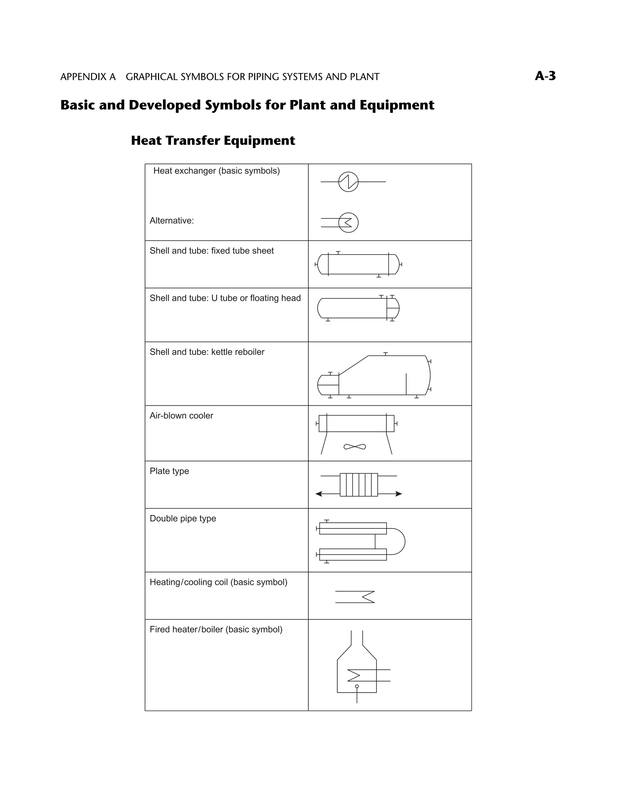
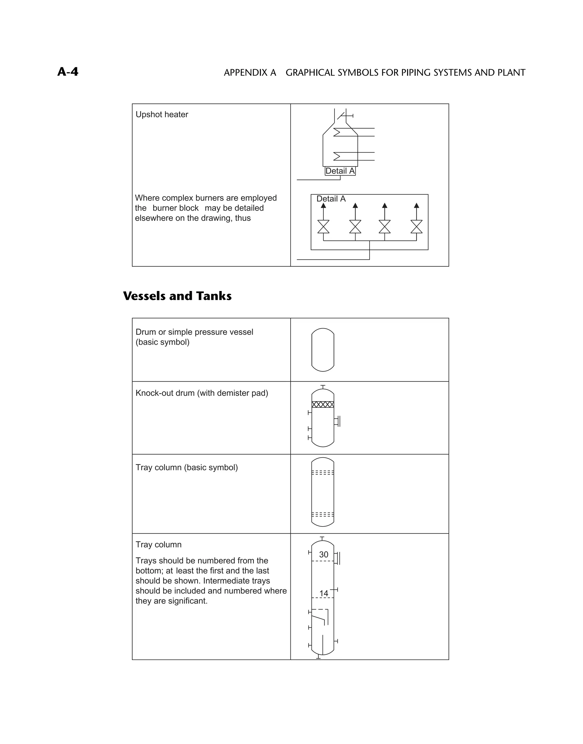
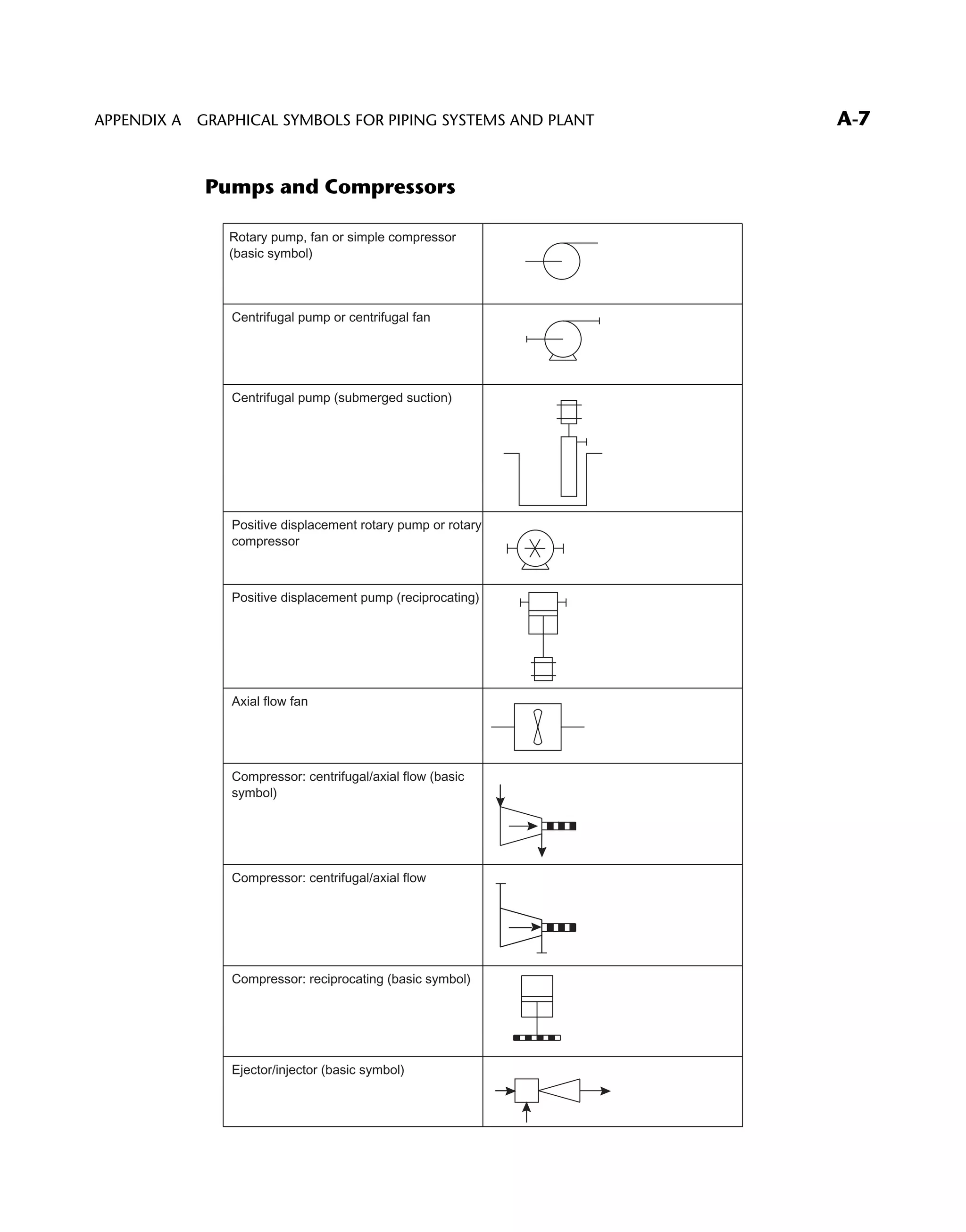
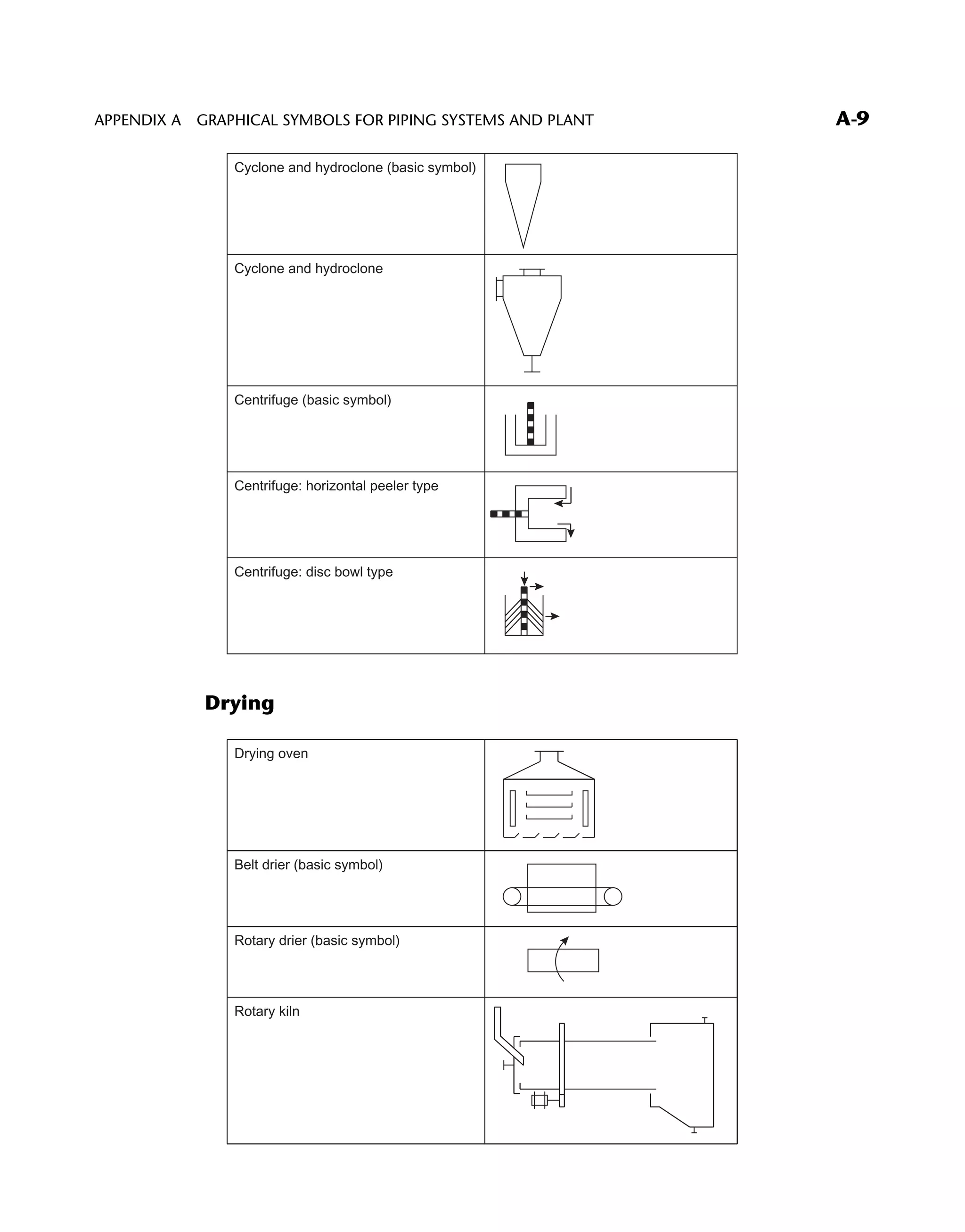
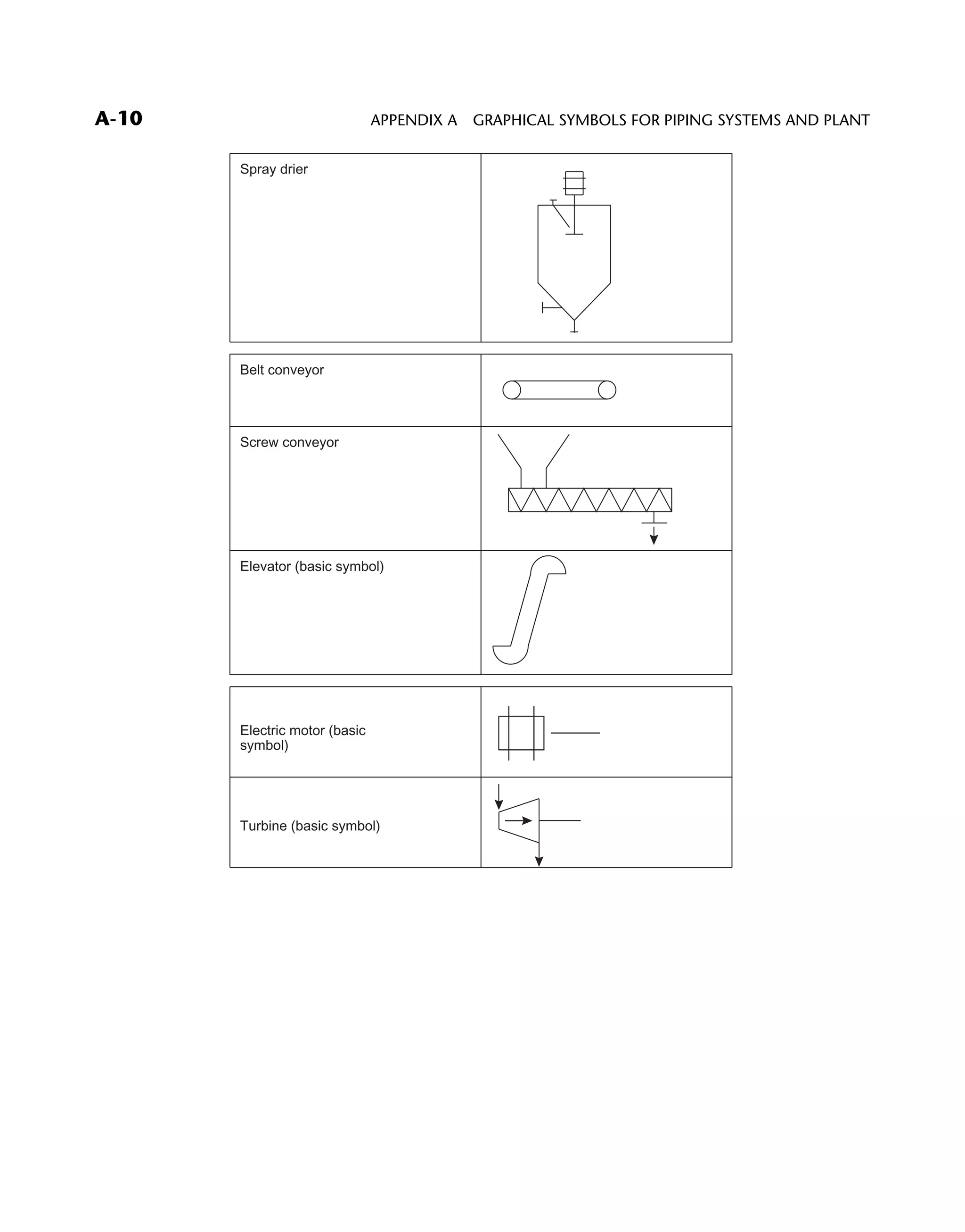
A GRAPHICAL SYMBOLS
FOR PIPING SYSTEMS
AND PLANT
BASED ON BS 1553: PART 1: 1977
Scope
This part of BS 1553 specifies graphical symbols for use in flow and piping diagrams
for process plant.
A-1
Symbols (or elements of Symbols) for Use in Conjunction with
Other Symbols
Mechanical linkage
Weight device
Electrical device
Vibratory or loading
device (any type)
Spray device
Rotary movement
Stirring device
Fan
Access point
Equipment penetration
(fixed)
Boundary line
Point of change
Discharge to atmosphere
Equipment branch:
general symbol
Note. The upper repre-
sentation does not
necessarily imply a
flange, merely the ter-
mination point. Where a
breakable connection is
required the branch/pipe
would be as shown in the
lower symbol
Equipment penetration
(removable)
APPENDIX A GRAPHICAL SYMBOLS FOR PIPING SYSTEMS AND PLANTA-2
Basic and Developed Symbols for Plant and Equipment
Heat Transfer Equipment
Heat exchanger (basic symbols)
Alternative:
Shell and tube: fixed tube sheet
Shell and tube: U tube or floating head
Shell and tube: kettle reboiler
Air-blown cooler
Plate type
Double pipe type
Heating/cooling coil (basic symbol)
Fired heater/boiler (basic symbol)
APPENDIX A GRAPHICAL SYMBOLS FOR PIPING SYSTEMS AND PLANT A-3
Upshot heater
Where complex burners are employed
the ‘‘burner block’’ may be detailed
elsewhere on the drawing, thus
Detail A
Detail A
Vessels and Tanks
Drum or simple pressure vessel
(basic symbol)
Knock-out drum (with demister pad)
Tray column (basic symbol)
Tray column
Trays should be numbered from the
bottom; at least the first and the last
should be shown. Intermediate trays
should be included and numbered where
they are significant.
30
14
APPENDIX A GRAPHICAL SYMBOLS FOR PIPING SYSTEMS AND PLANTA-4
Fluid contacting vessel (basic symbol)
Fluid contacting vessel
Support grids and distribution details
may be shown
Reaction or absorption vessel
(basic symbol)
Reaction or absorption vessel
Where it is necessary to show more than
one layer of material alternative
hatching should be used
Autoclave (basic symbol)
Autoclave
APPENDIX A GRAPHICAL SYMBOLS FOR PIPING SYSTEMS AND PLANT A-5
Open tank (basic symbol)
Open tank
Tank with fixed roof (with draw-off
sump)
Tank with floating roof (with roof drain)
Covered tank
Sealed tank
Clarifier or settling tank
Storage sphere
Gas holder (basic symbol for all types)
APPENDIX A GRAPHICAL SYMBOLS FOR PIPING SYSTEMS AND PLANTA-6
Pumps and Compressors
Rotary pump, fan or simple compressor
(basic symbol)
Centrifugal pump or centrifugal fan
Centrifugal pump (submerged suction)
Positive displacement rotary pump or rotary
compressor
Positive displacement pump (reciprocating)
Axial flow fan
Compressor: centrifugal/axial flow (basic
symbol)
Compressor: centrifugal/axial flow
Compressor: reciprocating (basic symbol)
Ejector/injector (basic symbol)
APPENDIX A GRAPHICAL SYMBOLS FOR PIPING SYSTEMS AND PLANT A-7
Solids Handling
Size reduction
Breaker gyratory
Roll crusher
Pulverizer : ball mill
Mixing (basic symbol)
Kneader
Ribbon blender
Double cone blender
Filter (basic symbol, simple batch)
Filter press (basic symbol)
Rotary filter, film drier or flaker
APPENDIX A GRAPHICAL SYMBOLS FOR PIPING SYSTEMS AND PLANTA-8
Cyclone and hydroclone (basic symbol)
Cyclone and hydroclone
Centrifuge (basic symbol)
Centrifuge: horizontal peeler type
Centrifuge: disc bowl type
Drying
Drying oven
Belt drier (basic symbol)
Rotary drier (basic symbol)
Rotary kiln
APPENDIX A GRAPHICAL SYMBOLS FOR PIPING SYSTEMS AND PLANT A-9
Spray drier
Belt conveyor
Screw conveyor
Elevator (basic symbol)
Electric motor (basic
symbol)
Turbine (basic symbol)
APPENDIX A GRAPHICAL SYMBOLS FOR PIPING SYSTEMS AND PLANTA-10

66595 apdx01

  • 1.
    A GRAPHICAL SYMBOLS FORPIPING SYSTEMS AND PLANT BASED ON BS 1553: PART 1: 1977 Scope This part of BS 1553 specifies graphical symbols for use in flow and piping diagrams for process plant. A-1
  • 2.
    Symbols (or elementsof Symbols) for Use in Conjunction with Other Symbols Mechanical linkage Weight device Electrical device Vibratory or loading device (any type) Spray device Rotary movement Stirring device Fan Access point Equipment penetration (fixed) Boundary line Point of change Discharge to atmosphere Equipment branch: general symbol Note. The upper repre- sentation does not necessarily imply a flange, merely the ter- mination point. Where a breakable connection is required the branch/pipe would be as shown in the lower symbol Equipment penetration (removable) APPENDIX A GRAPHICAL SYMBOLS FOR PIPING SYSTEMS AND PLANTA-2
  • 3.
    Basic and DevelopedSymbols for Plant and Equipment Heat Transfer Equipment Heat exchanger (basic symbols) Alternative: Shell and tube: fixed tube sheet Shell and tube: U tube or floating head Shell and tube: kettle reboiler Air-blown cooler Plate type Double pipe type Heating/cooling coil (basic symbol) Fired heater/boiler (basic symbol) APPENDIX A GRAPHICAL SYMBOLS FOR PIPING SYSTEMS AND PLANT A-3
  • 4.
    Upshot heater Where complexburners are employed the ‘‘burner block’’ may be detailed elsewhere on the drawing, thus Detail A Detail A Vessels and Tanks Drum or simple pressure vessel (basic symbol) Knock-out drum (with demister pad) Tray column (basic symbol) Tray column Trays should be numbered from the bottom; at least the first and the last should be shown. Intermediate trays should be included and numbered where they are significant. 30 14 APPENDIX A GRAPHICAL SYMBOLS FOR PIPING SYSTEMS AND PLANTA-4
  • 5.
    Fluid contacting vessel(basic symbol) Fluid contacting vessel Support grids and distribution details may be shown Reaction or absorption vessel (basic symbol) Reaction or absorption vessel Where it is necessary to show more than one layer of material alternative hatching should be used Autoclave (basic symbol) Autoclave APPENDIX A GRAPHICAL SYMBOLS FOR PIPING SYSTEMS AND PLANT A-5
  • 6.
    Open tank (basicsymbol) Open tank Tank with fixed roof (with draw-off sump) Tank with floating roof (with roof drain) Covered tank Sealed tank Clarifier or settling tank Storage sphere Gas holder (basic symbol for all types) APPENDIX A GRAPHICAL SYMBOLS FOR PIPING SYSTEMS AND PLANTA-6
  • 7.
    Pumps and Compressors Rotarypump, fan or simple compressor (basic symbol) Centrifugal pump or centrifugal fan Centrifugal pump (submerged suction) Positive displacement rotary pump or rotary compressor Positive displacement pump (reciprocating) Axial flow fan Compressor: centrifugal/axial flow (basic symbol) Compressor: centrifugal/axial flow Compressor: reciprocating (basic symbol) Ejector/injector (basic symbol) APPENDIX A GRAPHICAL SYMBOLS FOR PIPING SYSTEMS AND PLANT A-7
  • 8.
    Solids Handling Size reduction Breakergyratory Roll crusher Pulverizer : ball mill Mixing (basic symbol) Kneader Ribbon blender Double cone blender Filter (basic symbol, simple batch) Filter press (basic symbol) Rotary filter, film drier or flaker APPENDIX A GRAPHICAL SYMBOLS FOR PIPING SYSTEMS AND PLANTA-8
  • 9.
    Cyclone and hydroclone(basic symbol) Cyclone and hydroclone Centrifuge (basic symbol) Centrifuge: horizontal peeler type Centrifuge: disc bowl type Drying Drying oven Belt drier (basic symbol) Rotary drier (basic symbol) Rotary kiln APPENDIX A GRAPHICAL SYMBOLS FOR PIPING SYSTEMS AND PLANT A-9
  • 10.
    Spray drier Belt conveyor Screwconveyor Elevator (basic symbol) Electric motor (basic symbol) Turbine (basic symbol) APPENDIX A GRAPHICAL SYMBOLS FOR PIPING SYSTEMS AND PLANTA-10