
Downloaded 118 times
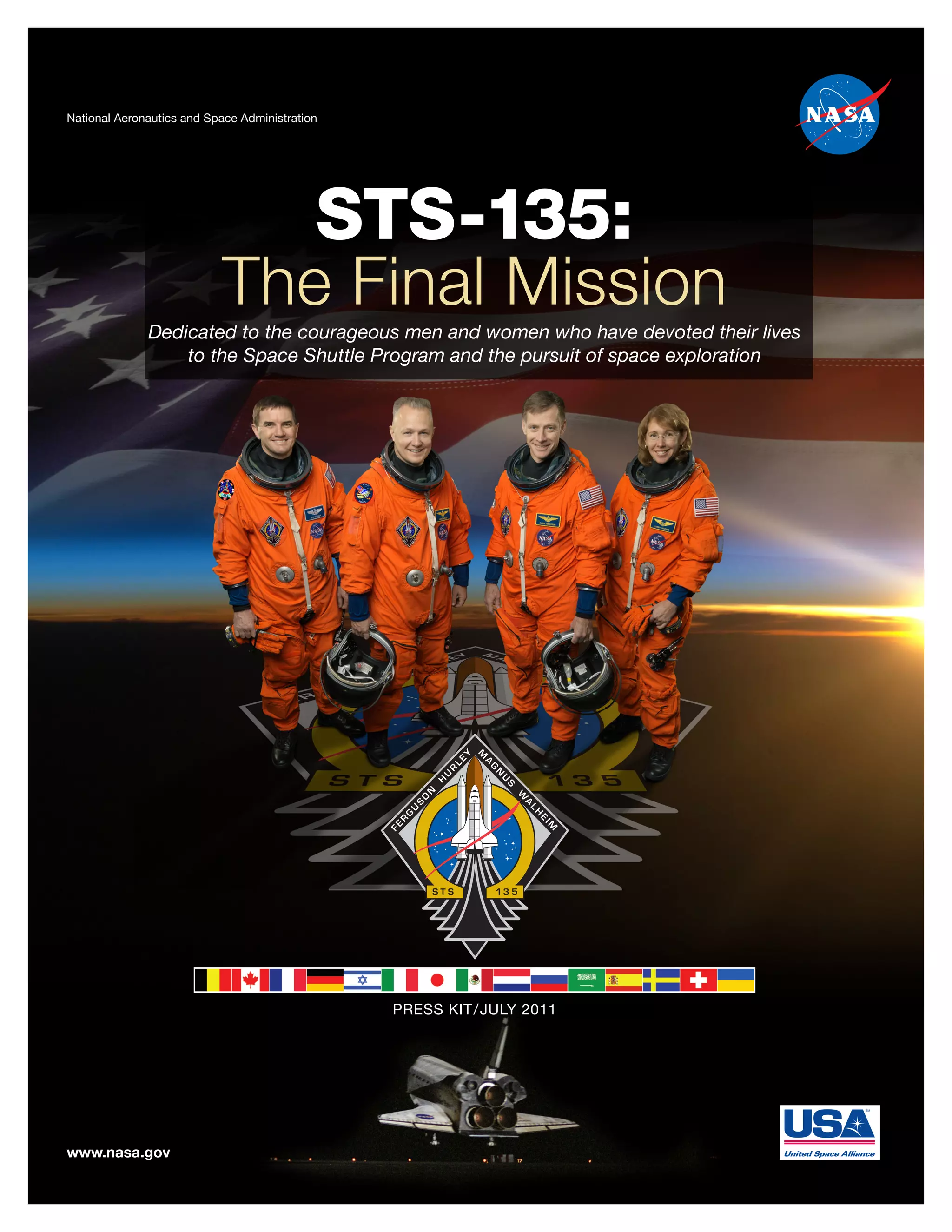


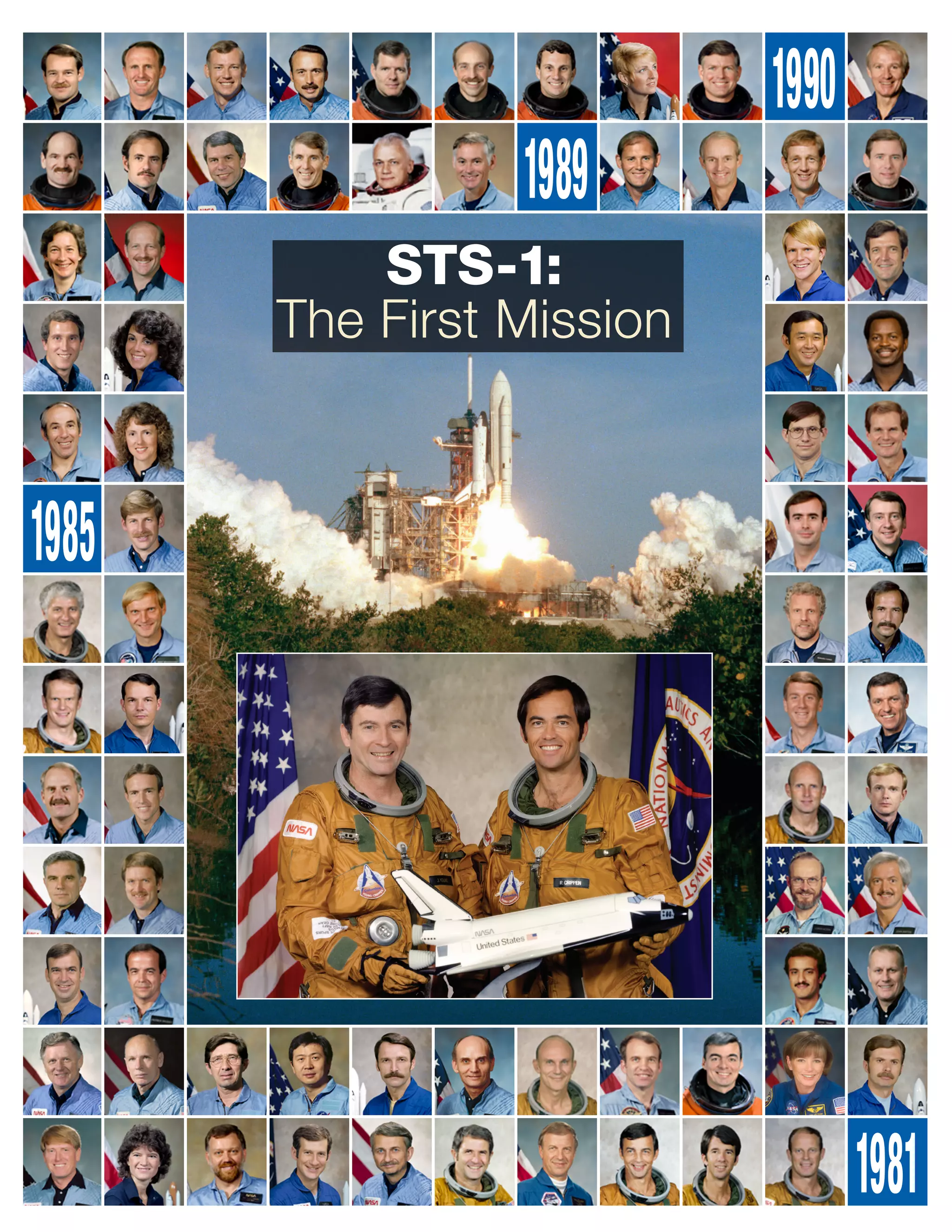


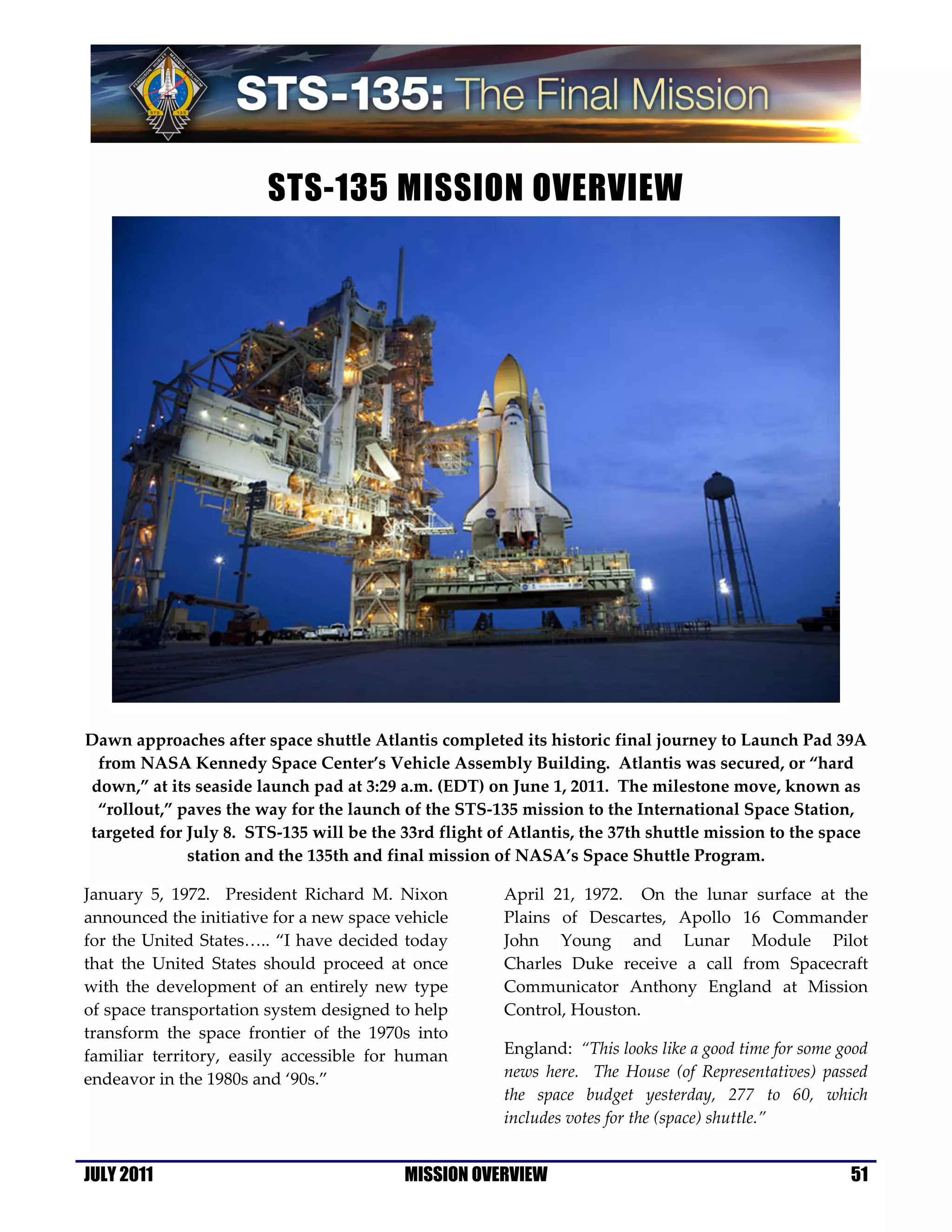


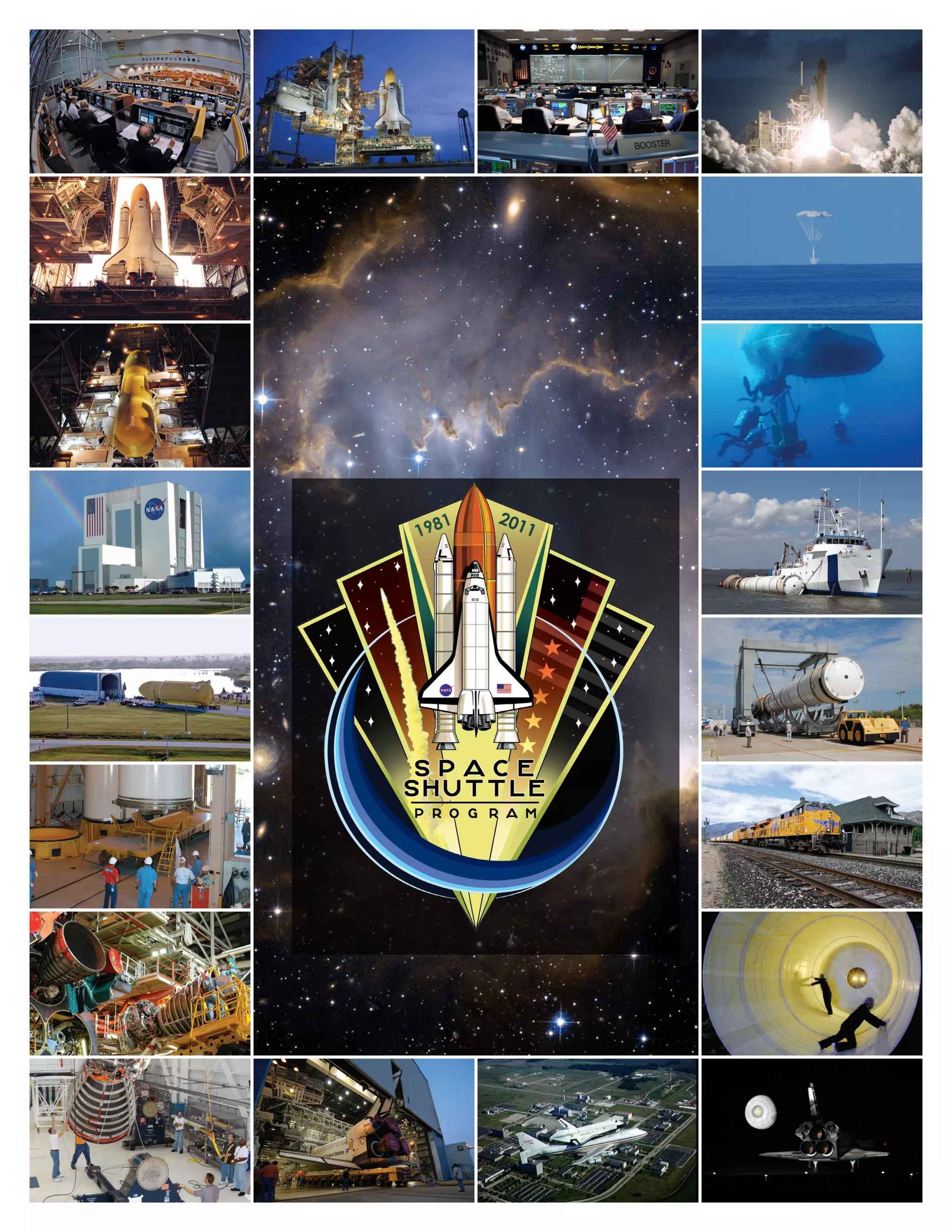
The document provides an overview of the STS-135 mission, which will be the final flight of the Space Shuttle Program. It discusses the history of the Space Shuttle from its development in the 1970s through 30 years of missions. STS-135 will deliver critical supplies to the International Space Station and conduct research. The multi-purpose logistics module loaded with supplies will be permanently attached to the station. STS-135 represents the end of an era as the Space Shuttle is retired after over 30 years of service.


