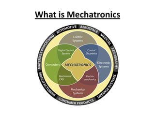
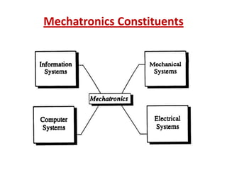
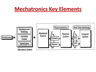
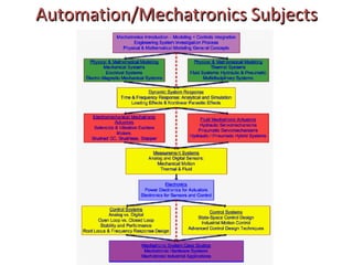
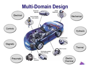
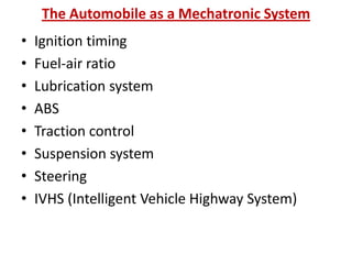
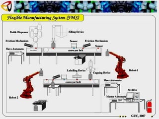
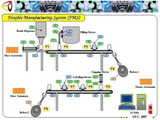
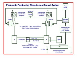
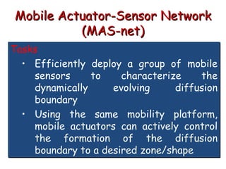
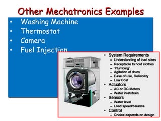
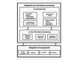
Mechatronics
What is Mechatronics
What Is Mechatronics?
• Mechatronics is a methodology used for the
optimal design of electromechanical
products.
• Multi-disciplinary system design has
employed a sequential design-by-discipline .
• The mechatronic design methodology is
based on concurrent, instead of sequential-
approach to discipline design, resulting in
products with more synergy approach.
Mechatronics Constituents
Mechatronics Key Elements
Automation/Mechatronics Subjects
Mechatronic s Key Elements
Mechatronics Key Elements
1-Information Systems
a- Modeling and Simulation
- Modeling is the process of representing the
behavior of a real system by a collection of
mathematical equations and logic.
- Simulation is the process of solving the model
and it is performed on a computer. The process
of simulation can be divided into three sections:
initialization, iteration, and termination
b- Automatic Controls
_ Mechatronics appears to be nothing more
than control system engineering.
What is the difference?
• The difference is the sequence of design steps
c-Optimization
• Optimization solves the problem of
distributing limited resources throughout a
system such that pre specified aspects of its
behavior are satisfied.
• It is applied to:
. Establish the optimal system configuration
. Identification of optimal trajectories
. Control system design
. Identification of model parameters
2- Electrical Systems
The following electrical components are
frequently used:
- Motors and generators
- Transducers
- Solid state devices including computers
- Circuits (signal conditioning, impedance
matching, amplifiers…)
-Contact devices (relays, circuit breakers,
switches…)
3- Sensors
• Sensors are required to monitor the performance of
machines and processes. Some of the more common
measurement variables in mechatronics systems are
temperature, speed, position, force, torque, and
acceleration.
• The characteristics that are important when one is
measuring these variables include the dynamics of the
sensor, stability, resolution, precision, robustness, size,
- and signal processing.
• The need for less expensive and precise sensors, as
well as integration of the sensor and signal processing
on a common carrier or on one chip, has become
important.
4- Actuators
• Actuation involves a physical acting on the process, such as the
ejection of a workpiece from a conveyor system ini-tiated by a
sensor. Actuators are usually electrical, mechanical, fluid power or
pneumatic based. They transform electrical inputs into mechanical
outputs such as force, angle, and position.
• Actuators can be classified into three general groups.
- Electromagnetic actuators, (e.g., AC and DC electrical motors,
stepper motors, electromagnets)
- Fluid power actuators, (e.g., hydraulics, pneumatics)
- Unconventional actuators (e.g., piezoelectric, magnetostrictive,
memory metal)
• There are also special actuators for high-precision applications that
require fast responses, They are often applied to controls that
compensate for friction, nonlinearities, and limiting parameters.
5- Computer Systems
- Computer system hardware is usually restricted to
computer-specific circuits and devices. These include
logic networks, flip flops, counters, timers, triggers,
integrated circuits, and microprocessors.
- Fast computer hardware is of little value without the
appropriate software
-Assembly language was the first step toward a higher-
Ievel language
-For more powerful (higher-level) programming
languages to be used, compilers were developed. Some
of the most well-known high-level languages are BASIC,
FORTRAN, C, and Pascal.
-Visual languages, including Matrixx, EasyS, SimuLink,
VisSim, and LabView.
6- Real-Time Interfacing
• It is process of fusing and synchronizing model,
sensor, and actuator information is called real-
time interfacing or hardware-in-the-loop
simulation.
• For mechatronics applications real-time
interfacing includes analog to digital (A/D) and
digital to analog (D/ A) conversion, analog signal
conditioning circuits, and sampling theory.
• The main purpose of the real-time interface
system is to provide data acquisition and control
function for the computer.
• Signals transmitted through the A/D and D/ A
devices fall into three categories:
. Analog
. Digital
. Frequency
Machine cell with robot
13. control valve- pneumatic gripper
14. Tactile sensor- gripper force
15. Servo amplifier- robot arm
16. Control computer- robot control
17. Display- robot status
18. Camera- part identification, guidance
CNC Machine
Aircraft Maneuvers
Ship Autopilot
The Automobile as a Mechatronic System
• Ignition timing
• Fuel-air ratio
• Lubrication system
• ABS
• Traction control
• Suspension system
• Steering
• IVHS (Intelligent Vehicle Highway System)
Using a radar to measure distance and velocity to autonomously maintain desired distance between vehicles.
Autonomous vehicle system design with sensors and actuators.
Temperature Control
Mobile Actuator-Sensor Network
(MAS-net)
Tasks
• Efficiently deploy a group of mobile
sensors to characterize the
dynamically evolving diffusion
boundary
• Using the same mobility platform,
mobile actuators can actively control
the formation of the diffusion
boundary to a desired zone/shape
MASNET Experimental Platform
(Conceptual Block Diagram)
•Actuated sensors
(mote-based robots)
take “plume” samples
•Wireless communication
system broadcasts commands
to actuated sensors
•Base station makes
plume prediction and
computes sensor locations
•Vision system for
locating sensors
•Air outlet
• Fog “Contaminant”
(orange) introduced
into air stream
•Fan blows
air (green)
through
system
2-D
System
Testbed
Concept
With Cover
Tag on top
A Closer Look!!!
1st Prototype Photos
Mote-based Robot:
USU MASmote
The Test Bed: Motes
GUI
Camera Driver
Serial Cable
Parallel Cable
Programming
Board
Mote (MICA Board)
TinyOS
Camera
GUI
Camera Driver
Serial Cable
Parallel Cable
Programming
Board
Mote (MICA Board)
TinyOS
Wireless Communication
Robots
Camera
MICA2
(Berkeley)
Control Board (USU)
AVR Atmega
128 (CPU)
CC1000 (Comm.)
2 Encoders
3 IR
(Sharp GP2D12)
2 Photo-
Resistors
2 Servos
Sensors
3V Power
6V Power
2ADC
2 PWM
3 ADC
2 ADC
Hardware Configuration of the
Mobility Platform
Software on Mobile Mote
Stack/Xnp
(Comm.)
TinyOS
User
Applications
TinyDB
TinySchema
Low Level
Lib
2 Encoders
2 Servos Other Sensors/Actuators
Other
Utilities of
TinyOS
Other Mechatronics Examples
• Washing Machine
• Thermostat
• Camera
• Fuel Injection
Fault Detection
Control System Generalised
Block Diagram
Signal
Conditioning
Feedback
And
Sensors
Process
Power
Electronics
Isolation
And
Buffering
System
Controller
Power Input
Reference
Input
Error
Signal
Control
Effort
Command
and Triggering
Input
Power
Output
Signal
Actual
Value
Digital Controller Analogue Part of System
Integrated Design Issues in Mechatronics
Ways of integration within mechatronics systems.

53_36765_ME591_2012_1__1_1_Mechatronics System Design.pdf

  • 1.
  • 2.
  • 3.
    What Is Mechatronics? •Mechatronics is a methodology used for the optimal design of electromechanical products. • Multi-disciplinary system design has employed a sequential design-by-discipline . • The mechatronic design methodology is based on concurrent, instead of sequential- approach to discipline design, resulting in products with more synergy approach.
  • 4.
  • 5.
  • 6.
  • 7.
  • 8.
    Mechatronics Key Elements 1-InformationSystems a- Modeling and Simulation - Modeling is the process of representing the behavior of a real system by a collection of mathematical equations and logic. - Simulation is the process of solving the model and it is performed on a computer. The process of simulation can be divided into three sections: initialization, iteration, and termination
  • 9.
    b- Automatic Controls _Mechatronics appears to be nothing more than control system engineering. What is the difference? • The difference is the sequence of design steps
  • 10.
    c-Optimization • Optimization solvesthe problem of distributing limited resources throughout a system such that pre specified aspects of its behavior are satisfied. • It is applied to: . Establish the optimal system configuration . Identification of optimal trajectories . Control system design . Identification of model parameters
  • 11.
    2- Electrical Systems Thefollowing electrical components are frequently used: - Motors and generators - Transducers - Solid state devices including computers - Circuits (signal conditioning, impedance matching, amplifiers…) -Contact devices (relays, circuit breakers, switches…)
  • 12.
    3- Sensors • Sensorsare required to monitor the performance of machines and processes. Some of the more common measurement variables in mechatronics systems are temperature, speed, position, force, torque, and acceleration. • The characteristics that are important when one is measuring these variables include the dynamics of the sensor, stability, resolution, precision, robustness, size, - and signal processing. • The need for less expensive and precise sensors, as well as integration of the sensor and signal processing on a common carrier or on one chip, has become important.
  • 13.
    4- Actuators • Actuationinvolves a physical acting on the process, such as the ejection of a workpiece from a conveyor system ini-tiated by a sensor. Actuators are usually electrical, mechanical, fluid power or pneumatic based. They transform electrical inputs into mechanical outputs such as force, angle, and position. • Actuators can be classified into three general groups. - Electromagnetic actuators, (e.g., AC and DC electrical motors, stepper motors, electromagnets) - Fluid power actuators, (e.g., hydraulics, pneumatics) - Unconventional actuators (e.g., piezoelectric, magnetostrictive, memory metal) • There are also special actuators for high-precision applications that require fast responses, They are often applied to controls that compensate for friction, nonlinearities, and limiting parameters.
  • 14.
    5- Computer Systems -Computer system hardware is usually restricted to computer-specific circuits and devices. These include logic networks, flip flops, counters, timers, triggers, integrated circuits, and microprocessors. - Fast computer hardware is of little value without the appropriate software -Assembly language was the first step toward a higher- Ievel language -For more powerful (higher-level) programming languages to be used, compilers were developed. Some of the most well-known high-level languages are BASIC, FORTRAN, C, and Pascal. -Visual languages, including Matrixx, EasyS, SimuLink, VisSim, and LabView.
  • 15.
    6- Real-Time Interfacing •It is process of fusing and synchronizing model, sensor, and actuator information is called real- time interfacing or hardware-in-the-loop simulation. • For mechatronics applications real-time interfacing includes analog to digital (A/D) and digital to analog (D/ A) conversion, analog signal conditioning circuits, and sampling theory. • The main purpose of the real-time interface system is to provide data acquisition and control function for the computer.
  • 16.
    • Signals transmittedthrough the A/D and D/ A devices fall into three categories: . Analog . Digital . Frequency
  • 17.
    Machine cell withrobot Machine cell with robot 13. control valve- pneumatic gripper 14. Tactile sensor- gripper force 15. Servo amplifier- robot arm 16. Control computer- robot control 17. Display- robot status 18. Camera- part identification, guidance
  • 18.
  • 19.
  • 20.
  • 25.
    The Automobile asa Mechatronic System • Ignition timing • Fuel-air ratio • Lubrication system • ABS • Traction control • Suspension system • Steering • IVHS (Intelligent Vehicle Highway System)
  • 26.
    Using a radarto measure distance and velocity to autonomously maintain desired distance between vehicles. Autonomous vehicle system design with sensors and actuators.
  • 27.
  • 33.
    Mobile Actuator-Sensor Network (MAS-net) Tasks •Efficiently deploy a group of mobile sensors to characterize the dynamically evolving diffusion boundary • Using the same mobility platform, mobile actuators can actively control the formation of the diffusion boundary to a desired zone/shape
  • 34.
  • 35.
    •Actuated sensors (mote-based robots) take“plume” samples •Wireless communication system broadcasts commands to actuated sensors •Base station makes plume prediction and computes sensor locations •Vision system for locating sensors •Air outlet • Fog “Contaminant” (orange) introduced into air stream •Fan blows air (green) through system 2-D System Testbed Concept
  • 36.
    With Cover Tag ontop A Closer Look!!!
  • 37.
  • 38.
    The Test Bed:Motes GUI Camera Driver Serial Cable Parallel Cable Programming Board Mote (MICA Board) TinyOS Camera GUI Camera Driver Serial Cable Parallel Cable Programming Board Mote (MICA Board) TinyOS Wireless Communication Robots Camera
  • 39.
    MICA2 (Berkeley) Control Board (USU) AVRAtmega 128 (CPU) CC1000 (Comm.) 2 Encoders 3 IR (Sharp GP2D12) 2 Photo- Resistors 2 Servos Sensors 3V Power 6V Power 2ADC 2 PWM 3 ADC 2 ADC Hardware Configuration of the Mobility Platform
  • 40.
    Software on MobileMote Stack/Xnp (Comm.) TinyOS User Applications TinyDB TinySchema Low Level Lib 2 Encoders 2 Servos Other Sensors/Actuators Other Utilities of TinyOS
  • 41.
    Other Mechatronics Examples •Washing Machine • Thermostat • Camera • Fuel Injection
  • 42.
  • 43.
    Control System Generalised BlockDiagram Signal Conditioning Feedback And Sensors Process Power Electronics Isolation And Buffering System Controller Power Input Reference Input Error Signal Control Effort Command and Triggering Input Power Output Signal Actual Value Digital Controller Analogue Part of System
  • 47.
    Integrated Design Issuesin Mechatronics
  • 48.
    Ways of integrationwithin mechatronics systems.