Download to read offline
![This document consists of 9 printed pages and 3 blank pages.
DC (NH/CGW) 59240/3
© UCLES 2013 [Turn over
UNIVERSITY OF CAMBRIDGE INTERNATIONAL EXAMINATIONS
General Certificate of Education Ordinary Level
*8619388720*
PHYSICS 5054/41
Paper 4 Alternative to Practical October/November 2013
1 hour
Candidates answer on the Question Paper.
No Additional Materials are required.
READ THESE INSTRUCTIONS FIRST
Write your Centre number, candidate number and name on all the work you hand in.
Write in dark blue or black pen.
You may use a pencil for any diagrams, graphs or rough working.
Do not use staples, paper clips, highlighters, glue or correction fluid.
DO NOT WRITE IN ANY BARCODES.
Answer all questions.
Electronic calculators may be used.
You may lose marks if you do not show your working or if you do not use appropriate units.
At the end of the examination, fasten all your work securely together.
The number of marks is given in brackets [ ] at the end of each question or part question.](https://image.slidesharecdn.com/5054w13qp4-150207053506-conversion-gate02/85/5054_w13_qp_4-1-320.jpg)
![This document consists of 9 printed pages and 3 blank pages.
DC (NH/CGW) 59240/3
© UCLES 2013 [Turn over
UNIVERSITY OF CAMBRIDGE INTERNATIONAL EXAMINATIONS
General Certificate of Education Ordinary Level
*8619388720*
PHYSICS 5054/41
Paper 4 Alternative to Practical October/November 2013
1 hour
Candidates answer on the Question Paper.
No Additional Materials are required.
READ THESE INSTRUCTIONS FIRST
Write your Centre number, candidate number and name on all the work you hand in.
Write in dark blue or black pen.
You may use a pencil for any diagrams, graphs or rough working.
Do not use staples, paper clips, highlighters, glue or correction fluid.
DO NOT WRITE IN ANY BARCODES.
Answer all questions.
Electronic calculators may be used.
You may lose marks if you do not show your working or if you do not use appropriate units.
At the end of the examination, fasten all your work securely together.
The number of marks is given in brackets [ ] at the end of each question or part question.](https://image.slidesharecdn.com/5054w13qp4-150207053506-conversion-gate02/75/5054_w13_qp_4-1-2048.jpg)

![3
5054/41/O/N/13© UCLES 2013 [Turn over
For
Examiner’s
Use
1 A student investigates a wooden sphere rolling down a plastic channel and falling to the floor.
The channel is set up at the end of a bench.
The sphere is initially held in the channel at the position shown in Fig. 1.1.
bench
sphere
plastic
channel
floor
Fig. 1.1 (not to scale)
(a) (i) On Fig. 1.1, mark and label the height h of the sphere above the bench before it is
released. [1]
(ii) Describe how the student ensures that the sphere is released from the same point
each time.
..................................................................................................................................
..............................................................................................................................[1]
(b) The sphere is released, rolls down the channel and lands on the floor.
When the sphere leaves the end of the channel, it is travelling horizontally.
On Fig. 1.1,
(i) draw a possible path of the sphere after it leaves the channel and until it hits the
floor, [1]
(ii) mark and label the horizontal distance d travelled by the sphere after it leaves the
channel and until it hits the floor. [1]
(c) Suggest a method for finding the point where the sphere hits the floor.
..........................................................................................................................................
......................................................................................................................................[1]](https://image.slidesharecdn.com/5054w13qp4-150207053506-conversion-gate02/85/5054_w13_qp_4-3-320.jpg)
![4
5054/41/O/N/13© UCLES 2013
For
Examiner’s
Use
(d) With h set at 30cm, the student repeats the experiment and measures d six times.
The student obtains the following values of d in cm.
68.5 64.0 67.0 66.5 65.0 64.5
Calculate the average distance dav.
Give your answer to a suitable number of significant figures.
dav = ....................................cm [1]
(e) The student repeats the experiment with different values of h. The results obtained for h
and dav are recorded in Fig. 1.2.
h/cm dav /cm
2 14
5 22
10 33
15 45
20 54
25 60
30
Fig. 1.2
On Fig. 1.2, write your value for dav from (d).
(i) By considering the experimental arrangement, suggest, with a reason, whether
dav = 0 when h = 0.
..................................................................................................................................
..............................................................................................................................[1]](https://image.slidesharecdn.com/5054w13qp4-150207053506-conversion-gate02/85/5054_w13_qp_4-4-320.jpg)
![5
5054/41/O/N/13© UCLES 2013 [Turn over
For
Examiner’s
Use
(ii) On Fig. 1.3, plot the graph of dav /cm on the y-axis against h/cm on the x-axis.
Start your axes from the origin. Draw a smooth curve of best fit.
0
0
[4]
Fig. 1.3
(iii) Another student suggests that dav is directly proportional to h.
Use your graph to explain whether this student is correct.
..................................................................................................................................
..................................................................................................................................
..............................................................................................................................[1]](https://image.slidesharecdn.com/5054w13qp4-150207053506-conversion-gate02/85/5054_w13_qp_4-5-320.jpg)
![6
5054/41/O/N/13© UCLES 2013
For
Examiner’s
Use
2 A group of students investigate their reaction times.
The students mark a 30cm strip of card in equal sections, as shown in Fig. 2.1.
1
2
3
4
5
6
7
8
9
10
strip of card
Fig. 2.1
Student A holds the card at one end so that it hangs vertically.
Student B holds his thumb and first finger about 2cm apart just below the lower end of the
card, as shown in Fig. 2.2.
2cm
B
A
1
2
3
4
5
6
7
8
9
10
Fig. 2.2
Student A releases the card.
Student B catches the card between his thumb and first finger, without moving his hand up
or down.
Several pairs of students perform the experiment.
(a) (i) Explain what happens if student B is not concentrating.
..................................................................................................................................
..............................................................................................................................[1]
(ii) State how the card shows which student has the shortest reaction time.
..................................................................................................................................
..............................................................................................................................[1]](https://image.slidesharecdn.com/5054w13qp4-150207053506-conversion-gate02/85/5054_w13_qp_4-6-320.jpg)
![7
5054/41/O/N/13© UCLES 2013 [Turn over
For
Examiner’s
Use
(b) The distance h, in centimetres, fallen by the card in time t, in seconds, is given by
h = 500t2.
(i) Calculate h for t = 0.1s.
h = ............................................ [1]
(ii) A student catches the card after it has fallen 15cm. Calculate his reaction time.
reaction time = ............................................ [1]
(iii) A teacher draws lines on the back of the card to calibrate it so that the students can
measure reaction times directly in seconds.
1. Explain what, in this case, is meant by calibrate.
...........................................................................................................................
.......................................................................................................................[1]
2. On Fig. 2.3, without further calculation, sketch the card calibrated by the
teacher.You may use your answer from (b)(ii). [1]
strip of card
0 0.1s
Fig. 2.3](https://image.slidesharecdn.com/5054w13qp4-150207053506-conversion-gate02/85/5054_w13_qp_4-7-320.jpg)
![8
5054/41/O/N/13© UCLES 2013
For
Examiner’s
Use
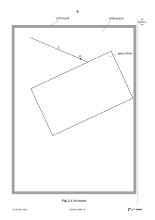
3 A student starts an experiment to determine the path of light through a glass block.
The student uses a rectangular glass block and optical pins. He places the glass block on a
sheet of paper on a soft board, as shown in Fig. 3.1.
The student draws a line L to represent an incident ray.
(a) (i) On Fig. 3.1, draw the normal at the point where L meets the glass block. [1]
(ii) On Fig. 3.1, label the angle of incidence i. Measure i.
i = ..............................................[1]
(b) The student then places a pin P1 on the incident ray, as shown in Fig. 3.1.
(i) Suggest a reason why the student uses a board under the piece of paper.
..................................................................................................................................
..............................................................................................................................[1]
(ii) The student places a second pin P2 on L. Suggest where, on L, pin P2 should be
placed.
..............................................................................................................................[1]
(iii) To find the path of the emergent ray, the student views P1 and P2 through the glass
block.
He moves his head until P1 and P2 are in line.
Explain why it is important for the pins to be vertical.
..................................................................................................................................
..............................................................................................................................[1]
(c) The student finds it difficult to mark the emergent ray with the apparatus as it is set up
in Fig. 3.1.
Suggest and explain a reason for this.
..........................................................................................................................................
..........................................................................................................................................
..........................................................................................................................................
......................................................................................................................................[2]](https://image.slidesharecdn.com/5054w13qp4-150207053506-conversion-gate02/85/5054_w13_qp_4-8-320.jpg)
![10
5054/41/O/N/13© UCLES 2013
For
Examiner’s
Use
4 (a) Describe an experiment to measure the resistance of a resistor using an ammeter and a
voltmeter.
Your account should include
• a circuit diagram,
• the readings taken,
• a method of taking a range of readings,
• a method of determining the resistance from the readings.
..........................................................................................................................................
..........................................................................................................................................
..........................................................................................................................................
..........................................................................................................................................
..........................................................................................................................................
......................................................................................................................................[4]
(b) Describe one way to improve the accuracy of the result.
..........................................................................................................................................
......................................................................................................................................[1]](https://image.slidesharecdn.com/5054w13qp4-150207053506-conversion-gate02/85/5054_w13_qp_4-10-320.jpg)


![This document consists of 8 printed pages.
DC (NH/SW) 64462/4
© UCLES 2013 [Turn over
UNIVERSITY OF CAMBRIDGE INTERNATIONAL EXAMINATIONS
General Certificate of Education Ordinary Level
*3818926035*
PHYSICS 5054/42
Paper 4 Alternative to Practical October/November 2013
1 hour
Candidates answer on the Question Paper.
No Additional Materials are required.
READ THESE INSTRUCTIONS FIRST
Write your Centre number, candidate number and name on all the work you hand in.
Write in dark blue or black pen.
You may use a pencil for any diagrams, graphs or rough working.
Do not use staples, paper clips, highlighters, glue or correction fluid.
DO NOT WRITE IN ANY BARCODES.
Answer all questions.
Electronic calculators may be used.
You may lose marks if you do not show your working or if you do not use appropriate units.
At the end of the examination, fasten all your work securely together.
The number of marks is given in brackets [ ] at the end of each question or part question.](https://image.slidesharecdn.com/5054w13qp4-150207053506-conversion-gate02/85/5054_w13_qp_4-13-320.jpg)
![2
5054/42/O/N/13© UCLES 2013
For
Examiner’s
Use
1 A student investigates how a magnetic force varies with distance.
A bar magnet is attracted to the iron base of a clamp stand, as shown in Fig. 1.1.
A newton meter is attached to the magnet.
newton meter
string
tape
magnetiron base
Fig. 1.1
The student pulls the newton meter vertically upwards and measures the force F required to
pull the magnet off the iron base.
(a) (i) Explain why it is difficult to measure F accurately.
..................................................................................................................................
............................................................................................................................. [1]
(ii) Describe a method the student can use to measure F more accurately.
..................................................................................................................................
............................................................................................................................. [1]
(b) Fig. 1.2 shows the maximum reading on the newton meter as the magnet is pulled
off the base.
N 0
1
2
3
4
5
6
7
8
9
10
Fig. 1.2
Record the force F shown on the newton meter.
F = ............................................... [1]](https://image.slidesharecdn.com/5054w13qp4-150207053506-conversion-gate02/85/5054_w13_qp_4-14-320.jpg)
![3
5054/42/O/N/13© UCLES 2013 [Turn over
For
Examiner’s
Use
(c) The student places one sheet of paper between the magnet and the iron base and
measures the force F to pull the magnet off the base.
He repeats the experiment, each time increasing the number n of sheets of paper.
The results obtained are recorded in Fig. 1.3.
n F/N
0
1 3.5
2 2.5
3 1.5
4 1.0
5 0.5
Fig. 1.3
On Fig. 1.3, add your value for F from (b).
(i) On Fig. 1.4, plot a graph of F/N on the y-axis against n on the x-axis.
Start your axes from the origin. Draw a smooth curve of best fit.
0
0
[4]
Fig. 1.4](https://image.slidesharecdn.com/5054w13qp4-150207053506-conversion-gate02/85/5054_w13_qp_4-15-320.jpg)
![4
5054/42/O/N/13© UCLES 2013
For
Examiner’s
Use
(ii) Describe how F varies with n.
..................................................................................................................................
............................................................................................................................. [1]
(d) The newton meter shown in Fig. 1.2 is not suitable for measuring F when there are more
than 5 sheets of paper. Suggest why.
..........................................................................................................................................
......................................................................................................................................[1]
(e) (i) The student repeats the experiment using paper of a different thickness. His new
value of F when n = 1 is 3.0N. State which paper is thicker. Give a reason for your
answer.
..................................................................................................................................
............................................................................................................................. [1]
(ii) Explain how using very thin paper improves the experiment.
..................................................................................................................................
............................................................................................................................. [1]
(f) Very thin sheets may be made from aluminium foil.
State and explain whether aluminium foil is a suitable material for this experiment.
..........................................................................................................................................
..................................................................................................................................... [1]](https://image.slidesharecdn.com/5054w13qp4-150207053506-conversion-gate02/85/5054_w13_qp_4-16-320.jpg)
![5
5054/42/O/N/13© UCLES 2013 [Turn over
For
Examiner’s
Use
2 A student investigates the reflection of light.
The student has available:
• a pin board,
• a sheet of plain paper,
• a plane mirror,
• optical pins,
• a pencil, ruler and protractor.
(a) Describe how the student uses the apparatus to verify that the angles of incidence and
reflection are equal.
Include a clear labelled diagram in your answer.
..........................................................................................................................................
..........................................................................................................................................
..........................................................................................................................................
..........................................................................................................................................
..........................................................................................................................................
..........................................................................................................................................
..........................................................................................................................................
..........................................................................................................................................
..................................................................................................................................... [4]
(b) The student carries out the experiment carefully.
Describe one practical technique that improves the accuracy of the experiment.
..........................................................................................................................................
..........................................................................................................................................
..................................................................................................................................... [1]](https://image.slidesharecdn.com/5054w13qp4-150207053506-conversion-gate02/85/5054_w13_qp_4-17-320.jpg)
![6
5054/42/O/N/13© UCLES 2013
For
Examiner’s
Use
3 A student uses a lemon to make a simple electric cell.
He inserts a copper strip and an iron nail into the lemon, as shown in Fig. 3.1.
Fig. 3.1
The student connects a centre-zero voltmeter between the copper strip and the iron nail to
measure the e.m.f. produced by the lemon cell.
(a) Fig. 3.2 shows the voltmeter with the reading obtained.
3
2
1
0
3
2
1
V
Fig. 3.2
(i) Record the e.m.f. shown on the voltmeter.
e.m.f. = ............................................... [1]
(ii) Suggest how the connecting leads from the voltmeter can be securely attached to
the strip and to the nail.
............................................................................................................................. [1]
(iii) State what happens if the connections to the voltmeter are reversed.
............................................................................................................................. [1]](https://image.slidesharecdn.com/5054w13qp4-150207053506-conversion-gate02/85/5054_w13_qp_4-18-320.jpg)
![7
5054/42/O/N/13© UCLES 2013 [Turn over
For
Examiner’s
Use
(b) Suggest one reason why lemons are not used to power simple electronic equipment
such as digital watches.
..................................................................................................................................... [1]
(c) (i) The student connects three lemon cells in series and measures the total e.m.f. with
the voltmeter.
1. State the total e.m.f. that you would expect.
e.m.f. = ............................................... [1]
2. On Fig. 3.3, draw the connections that the student uses.
v
[1]
Fig. 3.3
(ii) The student connects three lemon cells in parallel and measures the total e.m.f.
with the voltmeter.
1. State the total e.m.f. that you would expect.
e.m.f. = ............................................... [1]
2. On Fig. 3.4, draw the connections that the student uses.
v
[1]
Fig. 3.4](https://image.slidesharecdn.com/5054w13qp4-150207053506-conversion-gate02/85/5054_w13_qp_4-19-320.jpg)
![8
5054/42/O/N/13© UCLES 2013
For
Examiner’s
Use
4 A student is given a bag of ten similar marbles.
(a) The student uses a 30cm ruler to determine the average diameter of the marbles.
Describe how the student obtains an accurate value.
Include a labelled diagram showing how any additional apparatus is used.
..........................................................................................................................................
..........................................................................................................................................
..........................................................................................................................................
..........................................................................................................................................
..................................................................................................................................... [3]
(b) The student then measures the diameter d of one marble accurately using a micrometer.
The scale of the micrometer is shown in Fig. 4.1.
35
30
25
15
micrometer
10
mm
40
20
Fig. 4.1
(i) State the reading shown on the micrometer.
d = ............................................... [1]
(ii) Describe how the student checks that the marble is spherical.
..................................................................................................................................
............................................................................................................................. [1]
Permission to reproduce items where third-party owned material protected by copyright is included has been sought and cleared where possible. Every
reasonable effort has been made by the publisher (UCLES) to trace copyright holders, but if any items requiring clearance have unwittingly been included, the
publisher will be pleased to make amends at the earliest possible opportunity.
University of Cambridge International Examinations is part of the Cambridge Assessment Group. Cambridge Assessment is the brand name of University of
Cambridge Local Examinations Syndicate (UCLES), which is itself a department of the University of Cambridge.](https://image.slidesharecdn.com/5054w13qp4-150207053506-conversion-gate02/85/5054_w13_qp_4-20-320.jpg)

This document consists of experimental procedures for investigating physics concepts like projectile motion, reaction times, light refraction, and electrical resistance. It contains 9 pages of text describing 4 experiments with diagrams, questions, and space for recording results. The format includes introductory information, method sections, diagrams, calculation questions, and results tables for students to complete as part of hands-on physics lessons.