
Recommended
Recommended
More Related Content
Similar to 4_award_002_E.pdf
Similar to 4_award_002_E.pdf (20)
Recently uploaded
Recently uploaded (20)
4_award_002_E.pdf
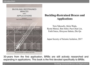
- 1. 1 Chapter 1: Composition and history of Buckling‐restrained Braces Buckling‐restrained Braces and Applications 1 Buckling-Restrained Braces and Applications Toru Takeuchi, Akira Wada, Ryota Matsui, Ben Sitler, Pao-Chun Lin, Fatih Sutcu, Hiroyasu Sakata, Zhe Qu Japan Society of Seismic Isolation, 2017 30-years from the first application, BRBs are still actively researched and expanding in applications. This book is the first devoted specifically to BRBs. introduction
- 2. 2 Chapter 1: Composition and history of Buckling‐restrained Braces Buckling‐restrained Braces and Applications 2 Contents Chapter 1: Composition and history of buckling-restrained braces Chapter 2: Restrainer design and clearances Chapter 3: Local bulging failure Chapter 4: Connection design and global stability Chapter 5: Cumulative deformation capacity Chapter 6: Performance test specification for BRB Chapter 7: BRBF Applications 7.1 Damage tolerant concept 7.2 Response evaluation of BRBF 7.3 Seismic retrofit with BRBs 7.4 Response Evaluation of BRBs Retrofit for RC Frames 7.5 Direct Connections to RC Frames 7.6 Applications for truss and spatial structures 7.7 Spine frame concepts Appendix A1 Typical BRB details A2 Rotational spring at connections A3 BRB buckling capacity introduction
- 3. 3 Chapter 1: Composition and history of Buckling‐restrained Braces Buckling‐restrained Braces and Applications 3 Concept of Buckling-restrained Brace Types of restrainer Appearance of typical BRB 1.1 Composition of buckling-restrained Braces (BRB) Mortar
- 4. 4 Chapter 1: Composition and history of Buckling‐restrained Braces Buckling‐restrained Braces and Applications 4 -600 -400 -200 0 200 400 600 -40 -20 0 20 40 Axial deformation (mm) Axial force (kN) Hysteresis of well‐designed BRB Clearance and eccentricity Development of higher buckling mode Restrainer Core plate
- 5. 5 Chapter 1: Composition and history of Buckling‐restrained Braces Buckling‐restrained Braces and Applications 5 The first application of Buckling‐restrained Brace (Unbonded Brace, 1987) Nippon Steel Headquarter No.2 (Tokyo) BRB installation BRB experiment 1987 M Fujimoto, A Wada, E Saeki, T Takeuchi, A Watanabe: Development of Unbonded Braces, Quarterly Column, No.115, pp.91‐96, 1990.1 1.2 History of Development
- 6. 6 Chapter 2: Restrainer Design and Clearances Buckling‐restrained Braces and Applications 6 Quality Requirement for Hysteresis models Inappropriate clearance Plastic strain concentration Local buckling Local bulging Uneven stiffness Degradation in compression side Uneven strength Uneven strength Local bulging Degradation in compression side Bulging-induced failure Tearing Fracture Slack (pin connection) Buckling Buckling-induced failure
- 7. 7 Chapter 2: Restrainer Design and Clearances Buckling‐restrained Braces and Applications 7 2. Restrainer Design and Clearance Global Stability, including: Restrainer End Higher Mode Buckling Connection Strength Fatigue Fracture Connections Restrainer Failure pattern and stability conditions 1.Restrainer successfully suppresses core first‐mode buckling (Chapter 2) 2.Debonding mechanism decouples axial demands and allows for Poisson effects (Chapter 2) 3.Restrainer wall bulging due to higher mode buckling is suppressed (Chapter 3) 4.Global out‐of‐plane stability is ensured, including connection (Chapter 4) 5.Low‐cycle fatigue capacity is sufficient for expected demands (Chapter 5)
- 9. 9 Chapter 4: Connection Design and Global Stability Buckling‐restrained Braces and Applications 9 The AIJ Recommendations provide rigorous evaluation methods for BRB connection out‐of‐plane buckling. Two concepts below are presented: AIJ (2009) Recommendations for stability design of steel structures. Architectural Institute of Japan. 4. Connection design and global stability Moment transfer capacity is lost at the end of restrainer EIB JEIB JEIB L0 L0 lB L0 Connection zone Connection zone Restrained zone =Plastic zone EIB > Bending moment transfer Gusset plate JEIB EIB > JEIB EIB KRg KRg Restrainer-end zone Connection zone Connection zone Restrainer-end zone Plastic zone Restrained zone 1: Cantilevered gusset 2: Restrainer end continuity
- 10. 10 Chapter 5: Cumulative Deformation Capacity until Fracture Buckling‐restrained Braces and Applications 10 Expected Plastic Zone Plastic Zone (a) Ordinary Tube Brace (b) Incomplete Buckling-restrained Brace (c) Complete Buckling-restrained Brace Local Buckling Mechanism Plastic stress concentration Mild local buckling and averaged strain distribution along plastic zone Friction Local buckling distribution until fracture 5. Cumulative deformation capacity
- 11. 11 Chapter 6: Performance Test Specification for BRB Buckling‐restrained Braces and Applications 11 (a) ANSI/AISC 341-05 and US practice Cycle Inelastic Deformation Cumulative strain Cumulative (Story drift angle) ( bm = 4 by ) ( by =0.25%) Inelastic strain by ×2 =2×4× by - by ) =0 by =2×4×0.25=2% =2×4×0=0% 0.5 bm ×2 =2×4× by - by ) =8 by =2×4×0.5=4% =2×4×0.25=2% 1.0 bm ×2 =2×4× by - by ) =24 by =2×4×1.0=8% =2×4×0.75=6% 1.5 bm ×2 =2×4× by - by ) =40 by =2×4×1.5=12% =2×4×1.25=10% .0 bm ×2 =2×4× by - by ) =56 by =2×4×2.0=16% =2×4×1.75=14% 1.5 bm ×4 =4×4× by - by ) =80 by =4×4×1.5=24% =4×4×1.25=20% Total =208 by =56% =52% (b) BCJ and Japanese practice Cycle Inelastic Deformation Cumulative strain Cumulative (Plastic length strain) ( by =0.25%) ( by =0.25%) Inelastic strain by ×3 =3×4× by - by ) =0 by =3×4×0.25=3% =3×4×0=0% 0.5%×3 =3×4× by - by ) =8 by =3×4×0.5=6% =3×4×0.25=3% 1.0% ×3 =3×4× by - by ) =36 by =3×4×1.0=12% =3×4×0.75=9% .0% ×3 =3×4× by - by ) =84 by =3×4×2.0=24% =3×4×1.75=21% ×3 =3×4× by - by ) =132 by =3×4×3.0=36% =3×4×2.75=33% Total =264 by =81% =66% (1.5 bm until fracture) (3.0% until fracture) 6. Performance test specification for BRB
- 12. 12 Chapter 7.1: Damage Tolerant Concept Buckling‐restrained Braces and Applications 12 Triton Square Project 7.1 Damage tolerant concept
- 13. 13 Chapter 7.1: Damage Tolerant Concept Buckling‐restrained Braces and Applications 13 Grand Tokyo North Tower Election of Large BRBF Following Damage Tolerant Projects
- 14. 14 Solar-panel Envelope Structure Flexible and Lightweight structure over the main frame Main Frame Spiral Layout of Energy-dissipation Fuses around Perimeter zones Open Space Energy Dissipation Brace Energy-dissipation Skins with Solar Cells 2. Disaster Prevention and Environmental Sustainability Grid skin structures
- 15. 15 Chapter 7.3: Seismic retrofit with BRBs Buckling‐restrained Braces and Applications 15 Midorigaoka-1st Building Retrofit concept 7.3 Seismic retrofit with BRBs Before Retrofit
- 17. 17 Chapter 7.5: Direct connections to RC frames Buckling‐restrained Braces and Applications 17 7.5 Direct connections to RC frames 2000 2000 2000 2800 2000 225 2000 kN Actuator 1000 kN Actuator + Beam Column For strut Out-of-plane restrained Out-of-plane restrained Out-of-plane restrained 40.4º +
- 18. 18 Chapter 7.6: Applications for truss and spatial structures Buckling‐restrained Braces and Applications 18 7.6 Applications for truss and spatial structures a) Truss structures △ △ △ △ △ △ Buckling BRB -2 -1.5 -1 -0.5 0 0.5 1 1.5 2 -2 -1.5 -1 -0.5 0 0.5 1 1.5 2 y 軸歪み [%] Force Limiting Function Devices Response Control for Truss Structures Device Layout Types for Response-controlled Truss Structures
- 19. 19 Chapter 7.6: Applications for truss and spatial structures Buckling‐restrained Braces and Applications 19 Horizontal Acceleration Vertical Acceleration Horizontal Input (R‐1) Roof with Dampers (R‐2) Base Isolated Roof (R‐3) Substructure with Dampers (R‐4) Entire Base Isolation Seismic Response of Raised Roof Device Layout for Response-controlled Roof Structures b) Roof structures