Download to read offline


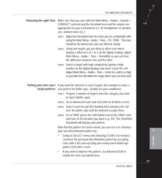
![THE MINELAB EXPLORER II
III
TABLE OF CONTENTS
INTRODUCTION.................................................................................................................... 1
About this manual ................................................................................................................................... 2
Introducing the Minelab Explorer II ....................................................................................................... 3
Minelab’s unique technology ................................................................................................................. 4
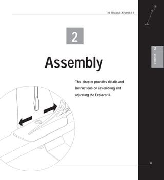
ASSEMBLY ............................................................................................................................ 9
Unpacking your Explorer II [easy reference] ...................................................................................... 10
Unpacking your Explorer II................................................................................................................... 11
Assembling the detector....................................................................................................................... 12
Connecting the search coil .................................................................................................................. 13
The shaft assembly............................................................................................................................... 15
Connecting the shaft assembly ........................................................................................................... 16
The handle assembly............................................................................................................................ 18
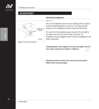
Headphones........................................................................................................................................... 20
Replacing and fitting the search coil................................................................................................... 21
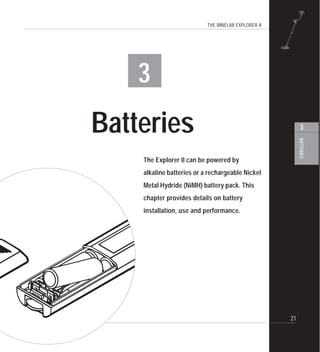
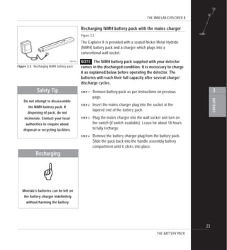
BATTERIES ......................................................................................................................... 23
The battery pack ................................................................................................................................... 24
Battery performance ............................................................................................................................. 27
THE CONTROL PANEL...................................................................................................... 29
The control panel [easy reference] ..................................................................................................... 30
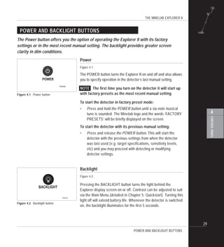
Power and Backlight buttons ............................................................................................................... 31
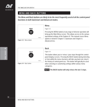
Menu and Back buttons ........................................................................................................................ 32
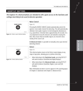
Shortcut buttons .................................................................................................................................... 33
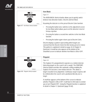
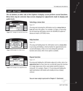
Shift buttons........................................................................................................................................... 35
contents
3
4
2
1](https://image.slidesharecdn.com/4901-0047rev1-150528201842-lva1-app6892/85/Instruction-Manual-Minelab-Explorer-II-Metal-Detector-English-Language-l4901-0047-3-320.jpg)
![THE MINELAB EXPLORER II
IV
www.minelab.com
5
TABLE OF CONTENTS
contents
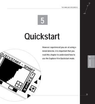
QUICKSTART ...................................................................................................................... 37
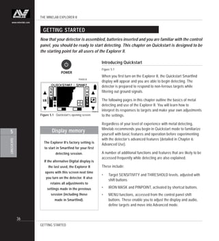
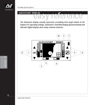
Getting started....................................................................................................................................... 38
Beginner use ......................................................................................................................................... 39
Quickstart display [easy reference]..................................................................................................... 40
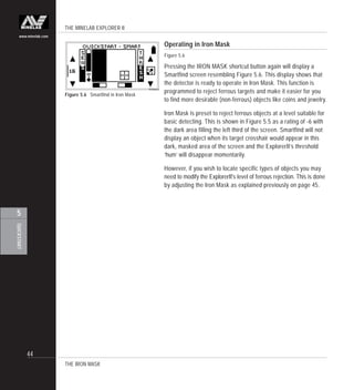
Quickstart’s Smartfind display ............................................................................................................. 42
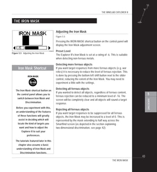
The Iron Mask........................................................................................................................................ 45
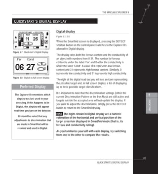
Quickstart’s Digital display................................................................................................................... 47
Modifying the display ............................................................................................................................ 48
Adjusting sensitivity .............................................................................................................................. 49
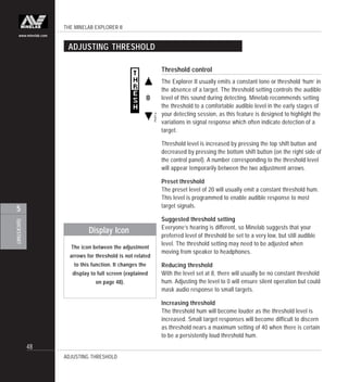
Adjusting threshold ............................................................................................................................... 50
Audio response ..................................................................................................................................... 51
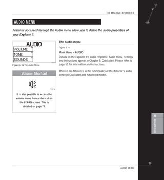
Audio menu ............................................................................................................................................ 52
Audio: adjusting the volume................................................................................................................. 53
Audio: adjusting the tone ..................................................................................................................... 55
Audio: adjusting the sounds................................................................................................................. 56
Testing target audio responses [tutorial] ............................................................................................ 58
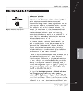
Pinpointing the object ........................................................................................................................... 59
Recovering the object ........................................................................................................................... 61
Selecting targets ................................................................................................................................... 62
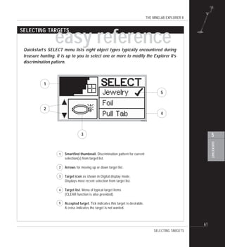
Selecting targets [easy reference] ...................................................................................................... 63
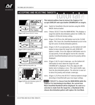
Accepting and rejecting targets [tutorial] ............................................................................................ 64
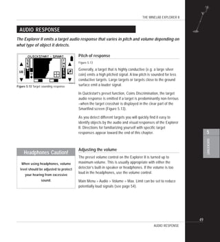
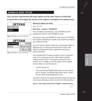
Advanced mode option ......................................................................................................................... 65](https://image.slidesharecdn.com/4901-0047rev1-150528201842-lva1-app6892/85/Instruction-Manual-Minelab-Explorer-II-Metal-Detector-English-Language-l4901-0047-4-320.jpg)
![THE MINELAB EXPLORER II
V
6
TABLE OF CONTENTS
contents
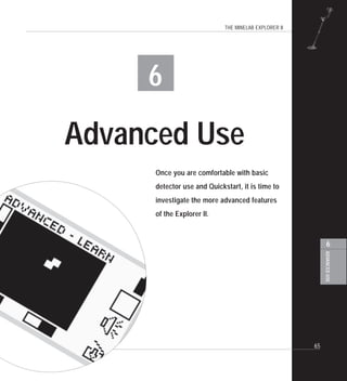
ADVANCED USE ................................................................................................................. 67
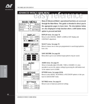
Advanced mode’s Main Menu [easy reference] ................................................................................ 68
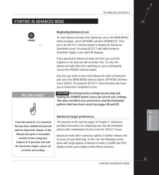
Starting in Advanced mode .................................................................................................................. 69
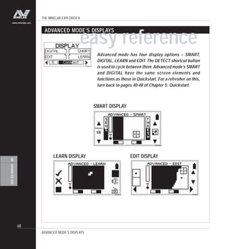
Advanced Mode’s displays [easy reference]..................................................................................... 70
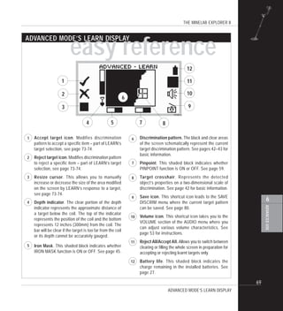
Advanced mode’s Learn display [easy reference] ............................................................................. 71
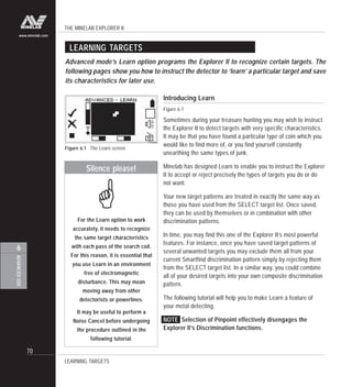
Learning targets .................................................................................................................................... 72
Learn’s target selection [tutorial] ......................................................................................................... 73
Advanced mode’s Edit display [easy reference]............................................................................... 75
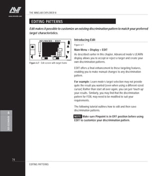
Editing patterns ..................................................................................................................................... 76
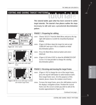
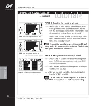
Editing and saving target patterns [tutorial] ...................................................................................... 77
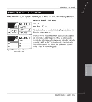
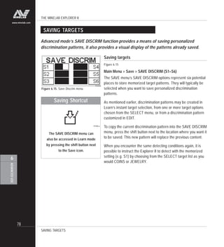
Advanced mode’s Select menu ........................................................................................................... 79
Saving targets ....................................................................................................................................... 80
Audio menu............................................................................................................................................ 81
Options menu ........................................................................................................................................ 82
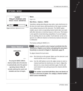
Options: noise ....................................................................................................................................... 83
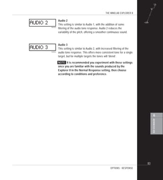
Options: response ................................................................................................................................. 84
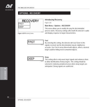
Options: recovery .................................................................................................................................. 86
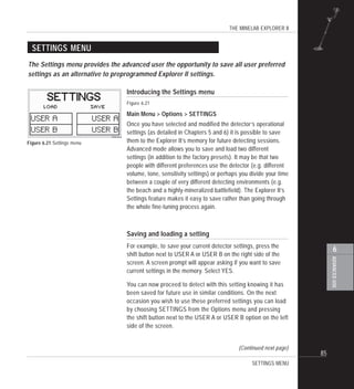
Settings menu........................................................................................................................................ 87](https://image.slidesharecdn.com/4901-0047rev1-150528201842-lva1-app6892/85/Instruction-Manual-Minelab-Explorer-II-Metal-Detector-English-Language-l4901-0047-5-320.jpg)

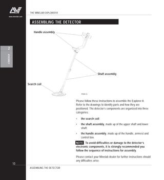
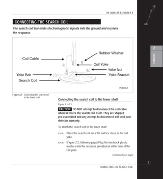

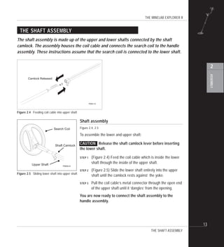
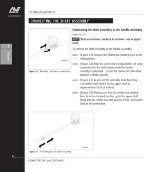
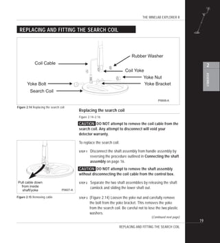


The Explorer II metal detector is assembled in three main steps: 1. Connecting the search coil to the lower shaft by sliding the coil yoke into the yoke bracket and securing it with a bolt. 2. Connecting the shaft assembly by joining the upper and lower shafts and securing them with a locking screw. 3. Connecting the handle assembly by attaching the armrest and control box to the shaft and securing everything with screws.


