The Fundamentals of
MachineVision
David Dechow
Staff Engineer, Intelligent
Robotics/Machine Vision
FANUC America Corporation
2.
INTRODUCTION AND OVERVIEW
TheFundamentals of Machine Vision
– What is Machine Vision
– The Machine Vision Market
– Industrial Uses of Machine Vision
3.
Introduction and Overview
•What is Machine Vision
– Machine vision is the substitution of the human visual sense and
judgment capabilities with a video camera and computer to
perform an inspection task. It is the automatic acquisition and
analysis of images to obtain desired data for controlling or
evaluating a specific part or activity.
– Key Points:
• Automated/Non‐Contact
• Acquisition
• Analysis
• Data
4.
Introduction and Overview
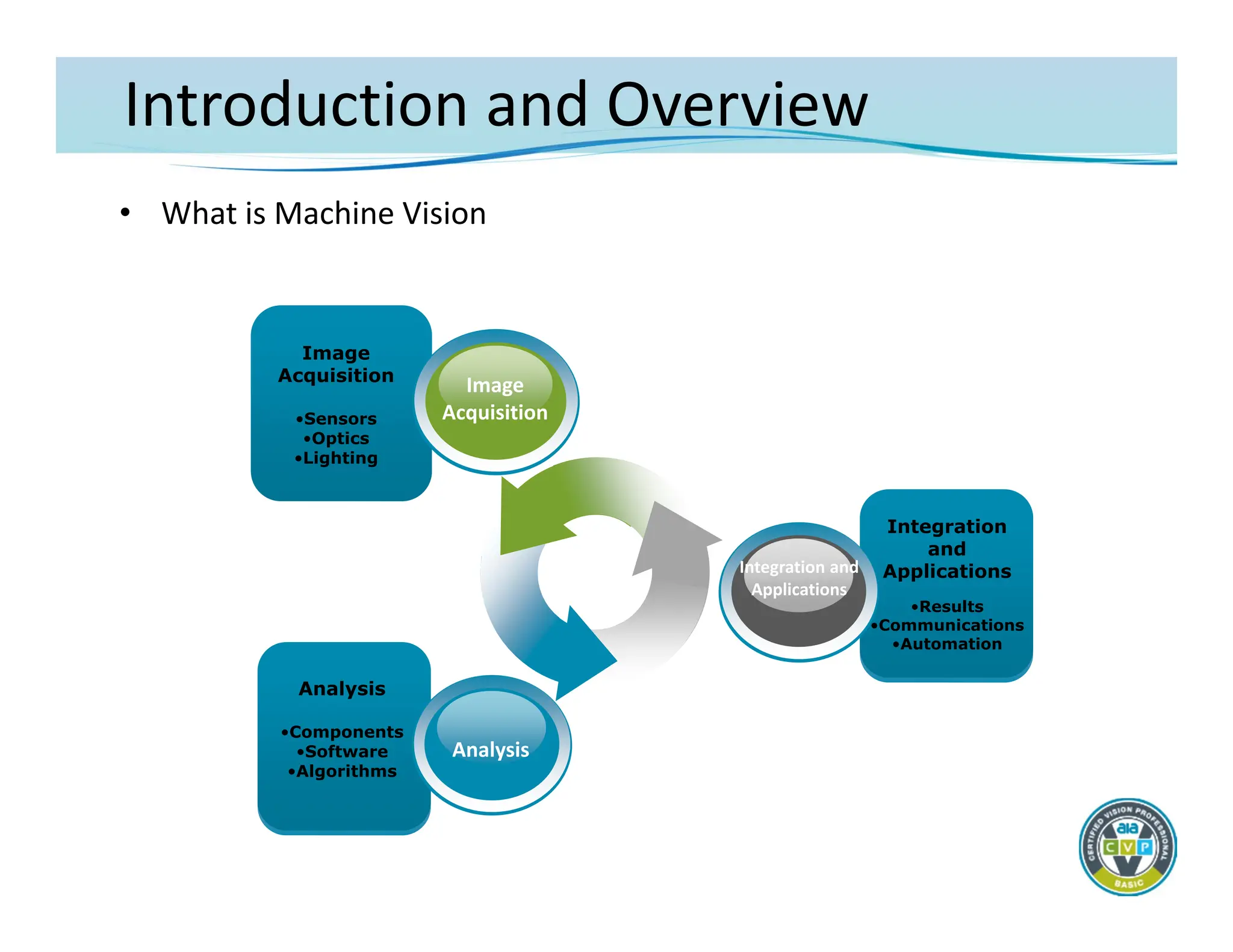
•What is Machine Vision
Image
Acquisition
•Sensors
•Optics
•Lighting
Image
Acquisition
Analysis
•Components
•Software
•Algorithms
Analysis
Integration
and
Applications
•Results
•Communications
•Automation
Integration and
Applications
5.
Introduction and Overview
•The Machine Vision Market
– Choices
• Well over 400 manufacturers and suppliers
• Diverse product offerings
– Confusion
• Product/component differentiation sometimes is unclear
• End‐users (the buyers) often don’t understand what they are
getting
– What’s important
• Components and techniques need to be better understood at
the end‐user level
• Advanced technology skills are necessary for competent
specification and integration
6.
Introduction and Overview
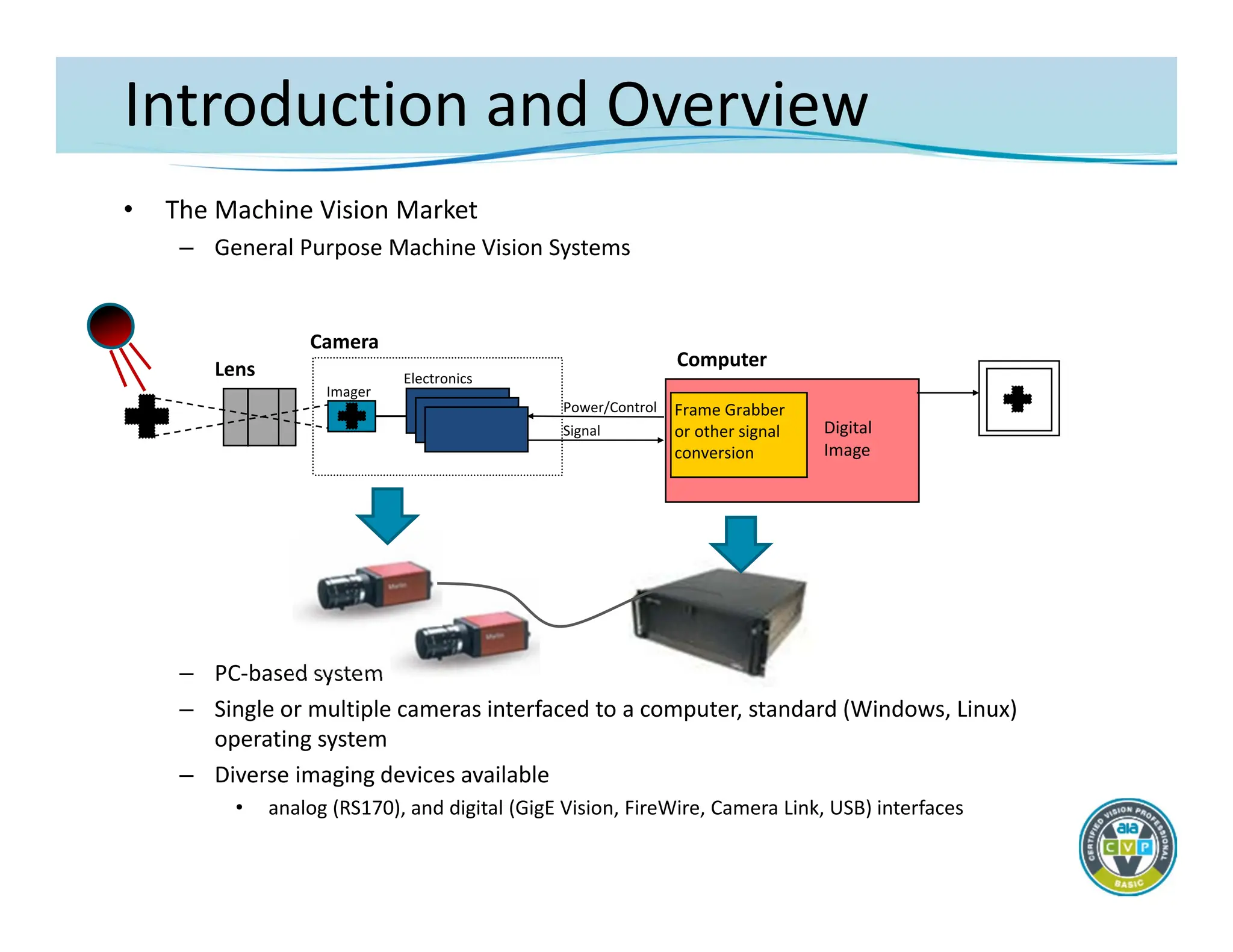
•The Machine Vision Market
– General Purpose Machine Vision Systems
– PC‐based system
– Single or multiple cameras interfaced to a computer, standard (Windows, Linux)
operating system
– Diverse imaging devices available
• analog (RS170), and digital (GigE Vision, FireWire, Camera Link, USB) interfaces
Camera
Lens
Imager
Electronics
Power/Control
Signal
Frame Grabber
or other signal
conversion
Computer
Digital
Image
7.
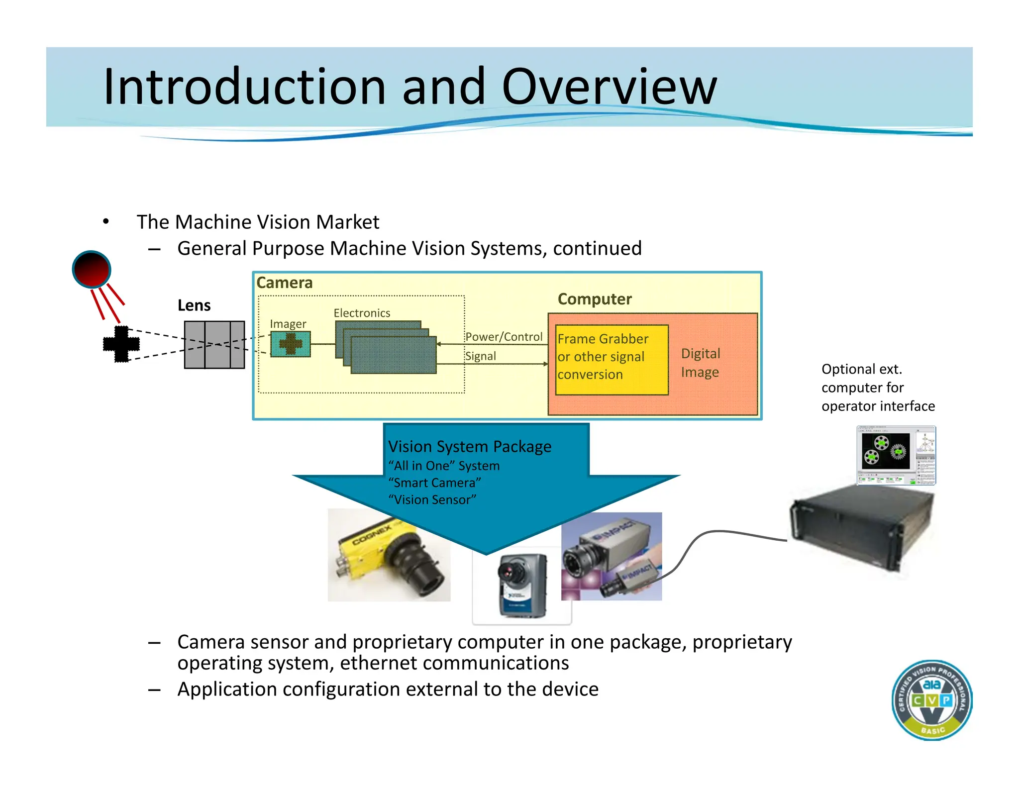
Introduction and Overview
•The Machine Vision Market
– General Purpose Machine Vision Systems, continued
– Camera sensor and proprietary computer in one package, proprietary
operating system, ethernet communications
– Application configuration external to the device
Camera
Lens
Imager
Electronics
Power/Control
Signal
Computer
Optional ext.
computer for
operator interface
Digital
Image
Frame Grabber
or other signal
conversion
Vision System Package
“All in One” System
“Smart Camera”
“Vision Sensor”
8.
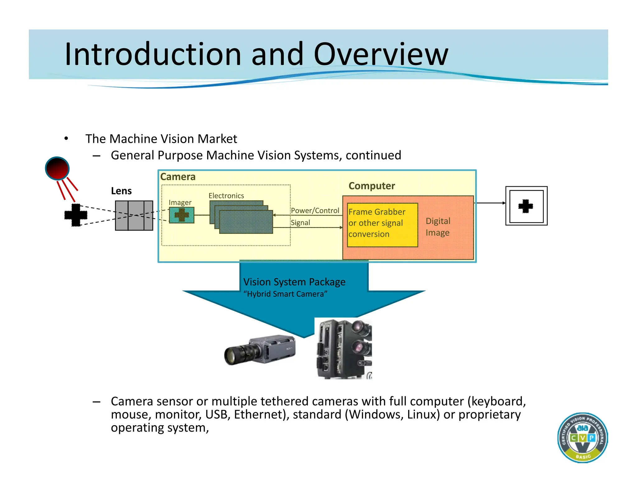
Introduction and Overview
•The Machine Vision Market
– General Purpose Machine Vision Systems, continued
– Camera sensor or multiple tethered cameras with full computer (keyboard,
mouse, monitor, USB, Ethernet), standard (Windows, Linux) or proprietary
operating system,
Camera
Lens
Imager
Electronics
Power/Control
Signal
Computer
Digital
Image
Frame Grabber
or other signal
conversion
Vision System Package
“Hybrid Smart Camera”
9.
Introduction and Overview
•The Machine Vision Market
– System feature overview
• PC‐based systems
– Most flexible and powerful system design
– Degree of difficulty varies by implementation
– Pricing varies depending upon architecture
• Smart Camera/Smart Sensor vision system
– Includes the easiest to use systems
» Some are more difficult to use
– Greater danger of over‐specifying capability
– Pricing varies widely – can be quite inexpensive
• Hybrid Smart Camera vision system
– Includes some of the features of both depending upon product
– Some architectures may pose integration challenges
10.
Introduction and Overview
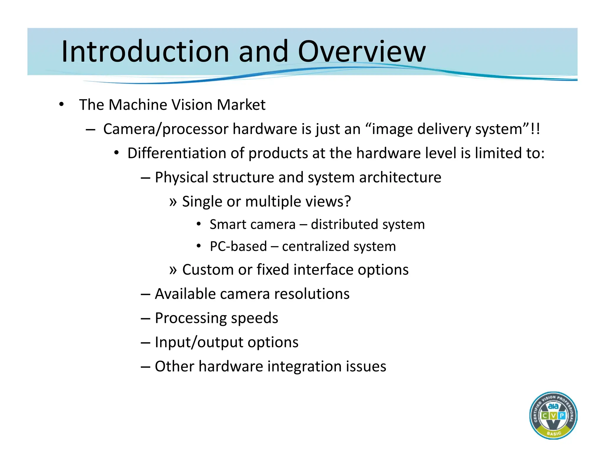
•The Machine Vision Market
– Camera/processor hardware is just an “image delivery system”!!
• Differentiation of products at the hardware level is limited to:
– Physical structure and system architecture
» Single or multiple views?
• Smart camera – distributed system
• PC‐based – centralized system
» Custom or fixed interface options
– Available camera resolutions
– Processing speeds
– Input/output options
– Other hardware integration issues
Introduction and Overview
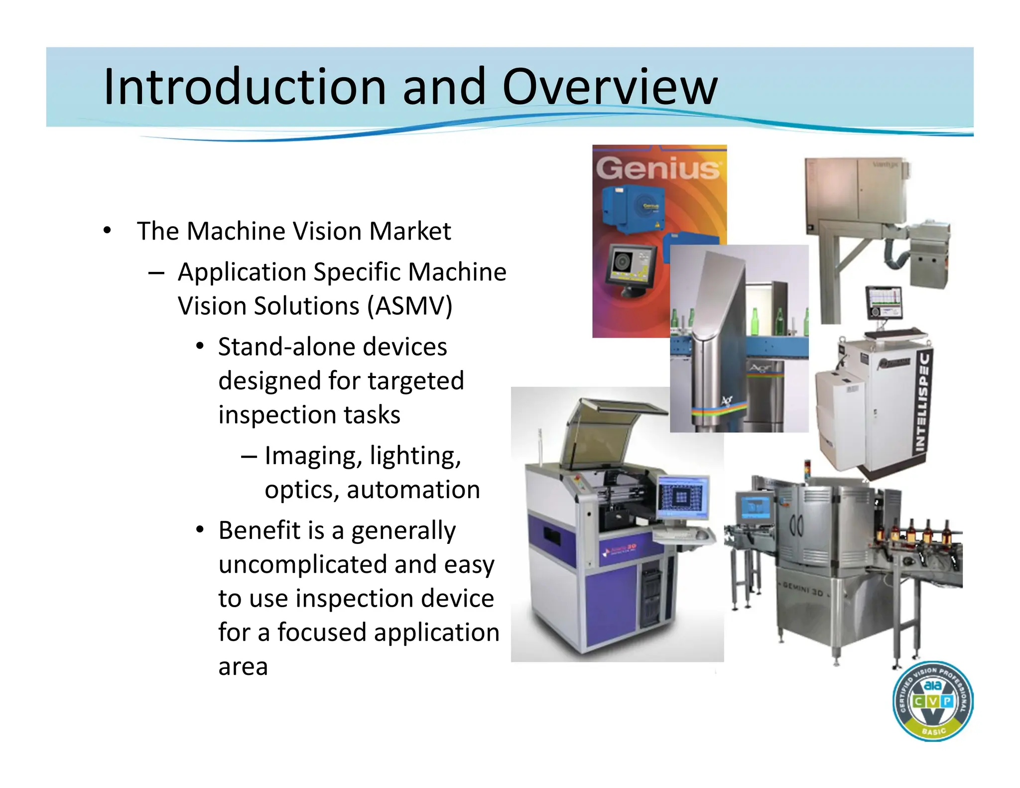
•The Machine Vision Market
– Application Specific Machine
Vision Solutions (ASMV)
• Stand‐alone devices
designed for targeted
inspection tasks
– Imaging, lighting,
optics, automation
• Benefit is a generally
uncomplicated and easy
to use inspection device
for a focused application
area
13.
Introduction and Overview
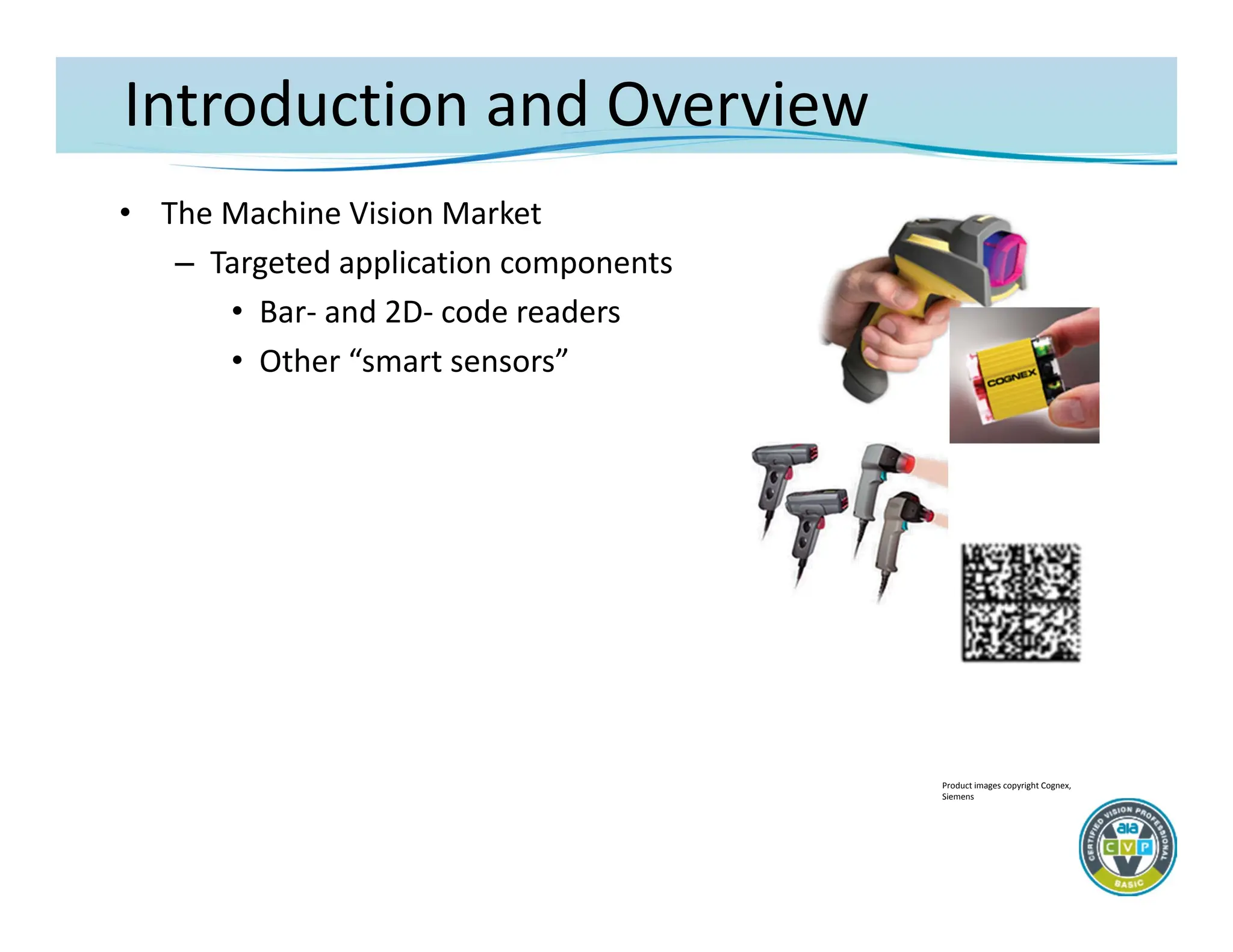
•The Machine Vision Market
– Targeted application components
• Bar‐ and 2D‐ code readers
• Other “smart sensors”
Product images copyright Cognex,
Siemens
14.
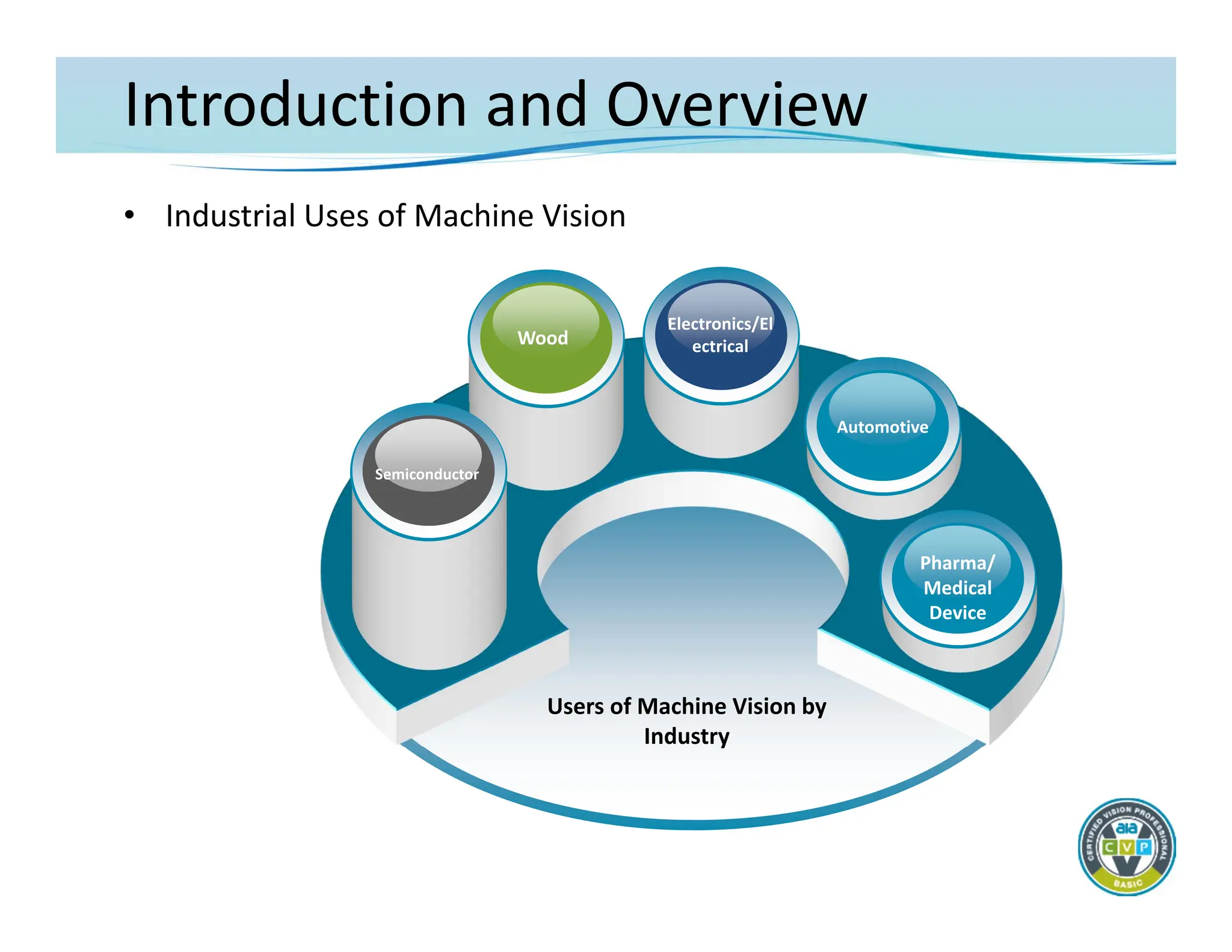
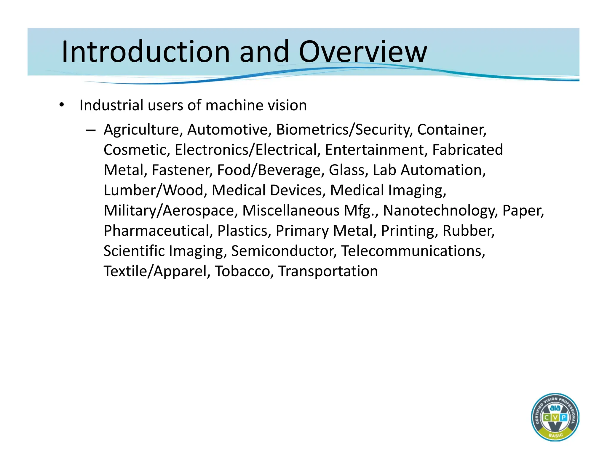
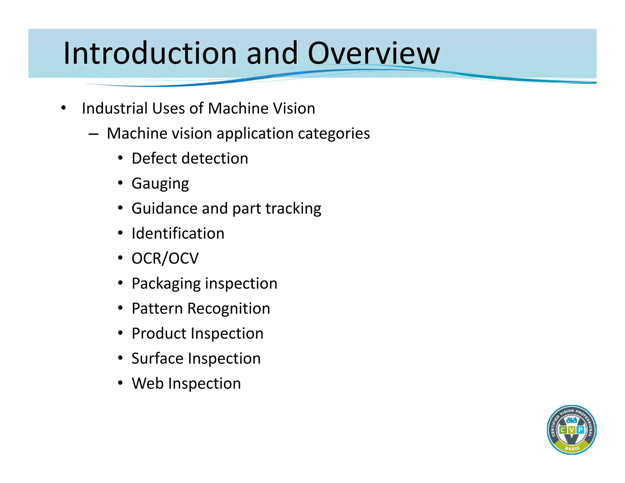
Introduction and Overview
•Industrial Uses of Machine Vision
Users of Machine Vision by
Industry
0Wood
Semiconductor
Electronics/El
ectrical
Automotive
Pharma/
Medical
Device
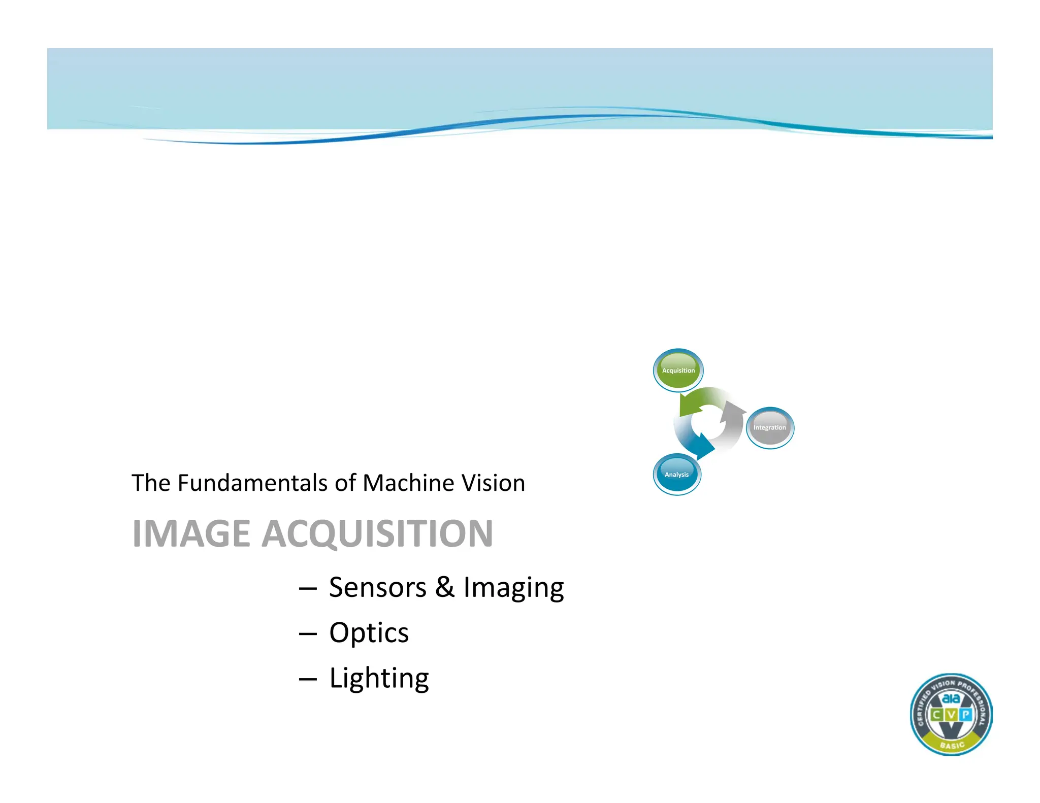
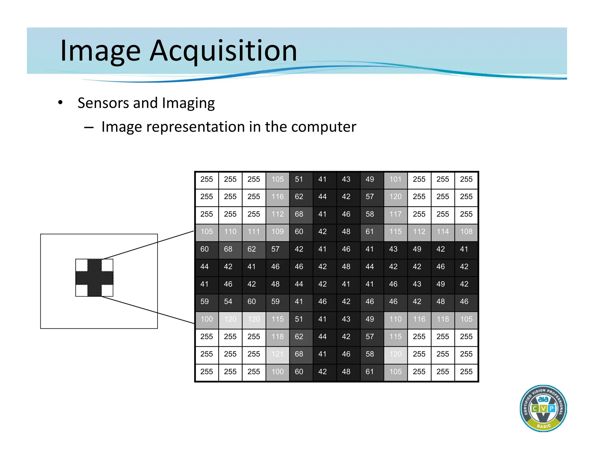
Image Acquisition
• Nothinghappens in a machine vision application without the
successful capture of a very high quality image
– Image quality: correct resolution for the target application with
best possible feature contrast
• Resolution – determined by sensor size and quality of optics
• Feature contrast – determined by correct lighting technique
and quality of optics
– Imaging is said to contribute more than 85% to the success of
any machine vision application
– The goal of machine vision image acquisition is to create an
image that is usable by the technology – not necessarily one
that’s pleasing to the human eye
19.
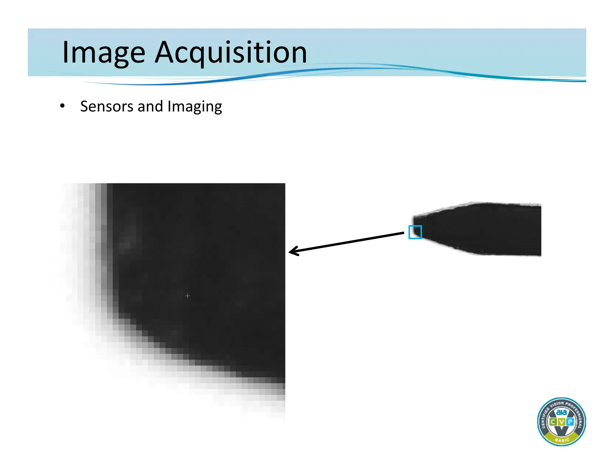
Image Acquisition
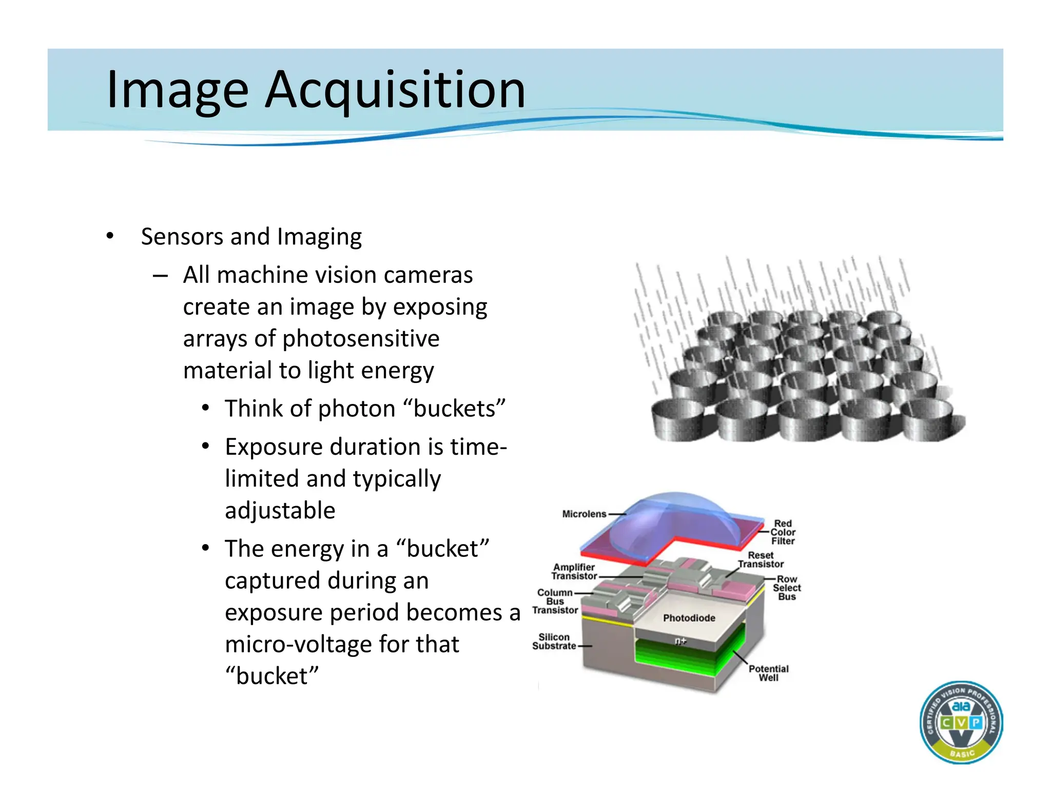
• Sensorsand Imaging
– All machine vision cameras
create an image by exposing
arrays of photosensitive
material to light energy
• Think of photon “buckets”
• Exposure duration is time‐
limited and typically
adjustable
• The energy in a “bucket”
captured during an
exposure period becomes a
micro‐voltage for that
“bucket”
20.
Image Acquisition
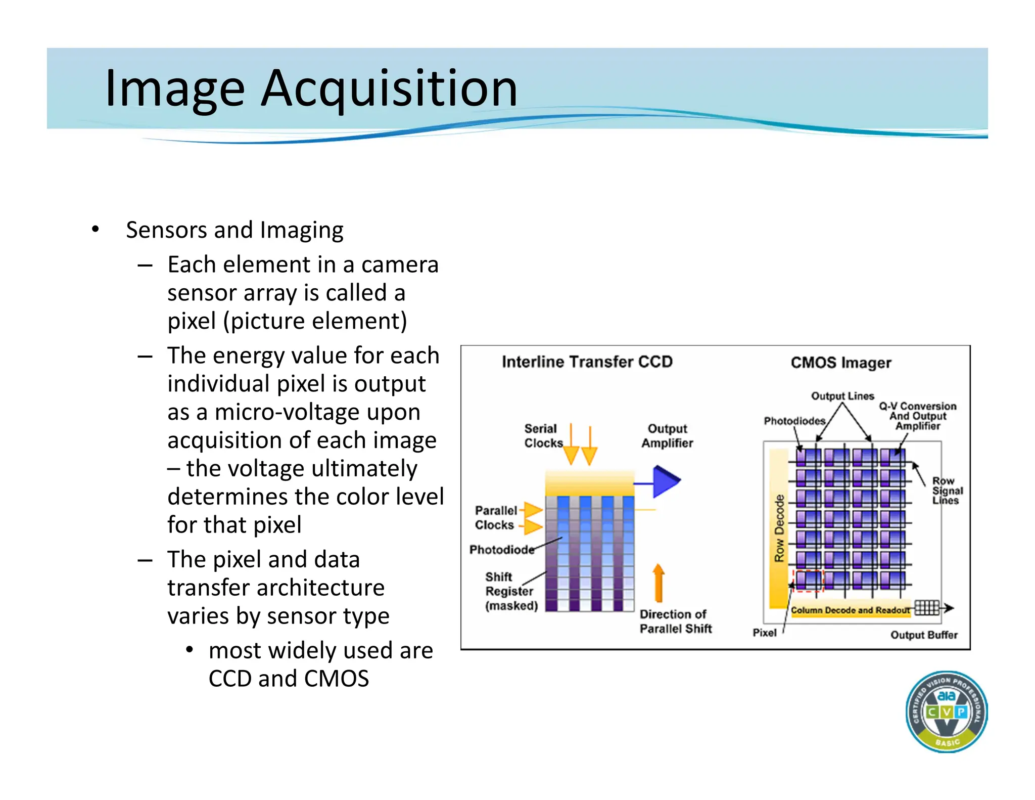
• Sensorsand Imaging
– Each element in a camera
sensor array is called a
pixel (picture element)
– The energy value for each
individual pixel is output
as a micro‐voltage upon
acquisition of each image
– the voltage ultimately
determines the color level
for that pixel
– The pixel and data
transfer architecture
varies by sensor type
• most widely used are
CCD and CMOS
21.
Image Acquisition
• Sensorsand Imaging
– The imaging sensor array comes in different physical layouts
• Area
• Line
– Size of the chip varies widely as does the number of individual
picture elements (pixels)
• Typical area chip for machine vision: from .3 to 5+ Mpix
– 640 to 2048+ pixels (horizontal)
– Physical sizes from ¼” diag. up to 1”+
• Typical line scan array: from 1K to 12K+ pixels
– Physical sizes from about 15mm to 90mm+
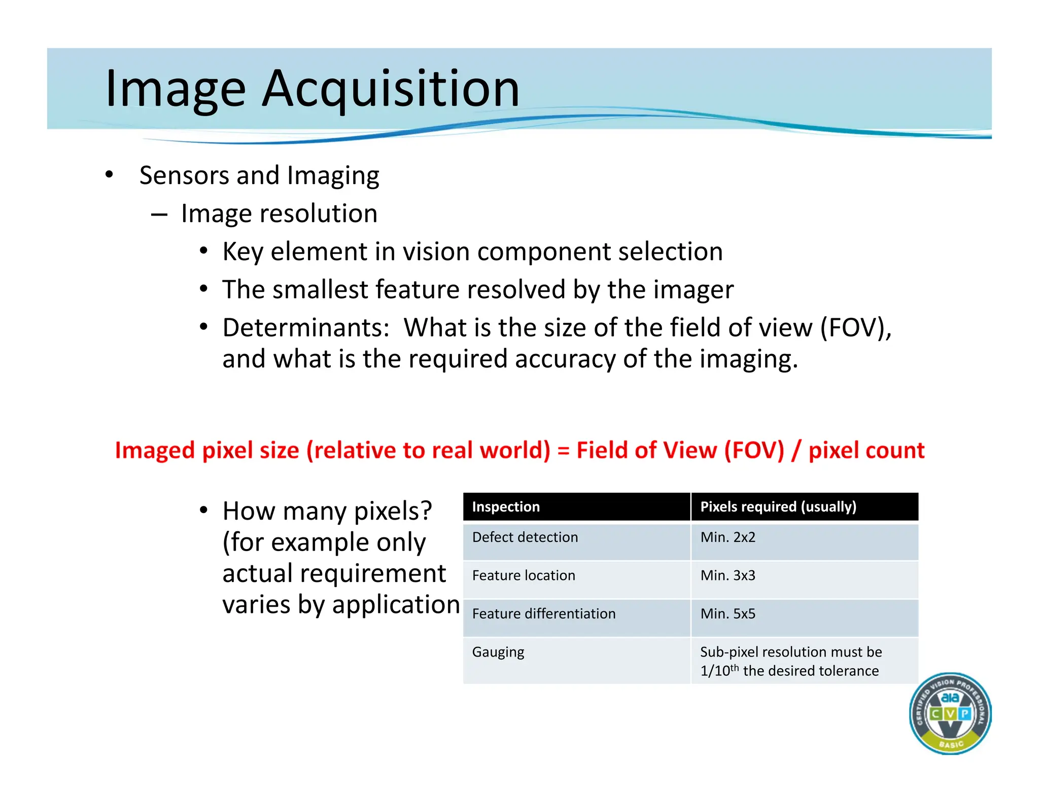
Image Acquisition
• Sensorsand Imaging
– Image resolution
• Key element in vision component selection
• The smallest feature resolved by the imager
• Determinants: What is the size of the field of view (FOV),
and what is the required accuracy of the imaging.
• How many pixels?
(for example only
actual requirement
varies by application)
Inspection Pixels required (usually)
Defect detection Min. 2x2
Feature location Min. 3x3
Feature differentiation Min. 5x5
Gauging Sub‐pixel resolution must be
1/10th the desired tolerance
26.
Image Acquisition
• Sensorsand Imaging
– Image Resolution
• Examples
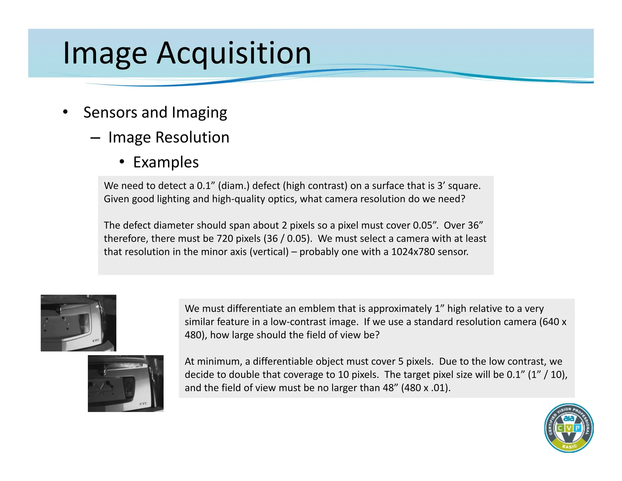
We need to detect a 0.1” (diam.) defect (high contrast) on a surface that is 3’ square.
Given good lighting and high‐quality optics, what camera resolution do we need?
The defect diameter should span about 2 pixels so a pixel must cover 0.05”. Over 36”
therefore, there must be 720 pixels (36 / 0.05). We must select a camera with at least
that resolution in the minor axis (vertical) – probably one with a 1024x780 sensor.
We must differentiate an emblem that is approximately 1” high relative to a very
similar feature in a low‐contrast image. If we use a standard resolution camera (640 x
480), how large should the field of view be?
At minimum, a differentiable object must cover 5 pixels. Due to the low contrast, we
decide to double that coverage to 10 pixels. The target pixel size will be 0.1” (1” / 10),
and the field of view must be no larger than 48” (480 x .01).
27.
Image Acquisition
• Optics
–Application of optical components
• Machine vision requires fundamental understanding of the
physics of lens design and performance
• Goal: specify the correct lens
– Create a desired field of view (FOV)
– Achieve a specific or acceptable working distance (WD)
– Project the image on a selected sensor based on sensor
size – primary magnification (PMAG)
– Create the highest level of contrast between features of
interest and the surrounding background; with the
greatest possible imaging accuracy
28.
Image Acquisition
• Optics
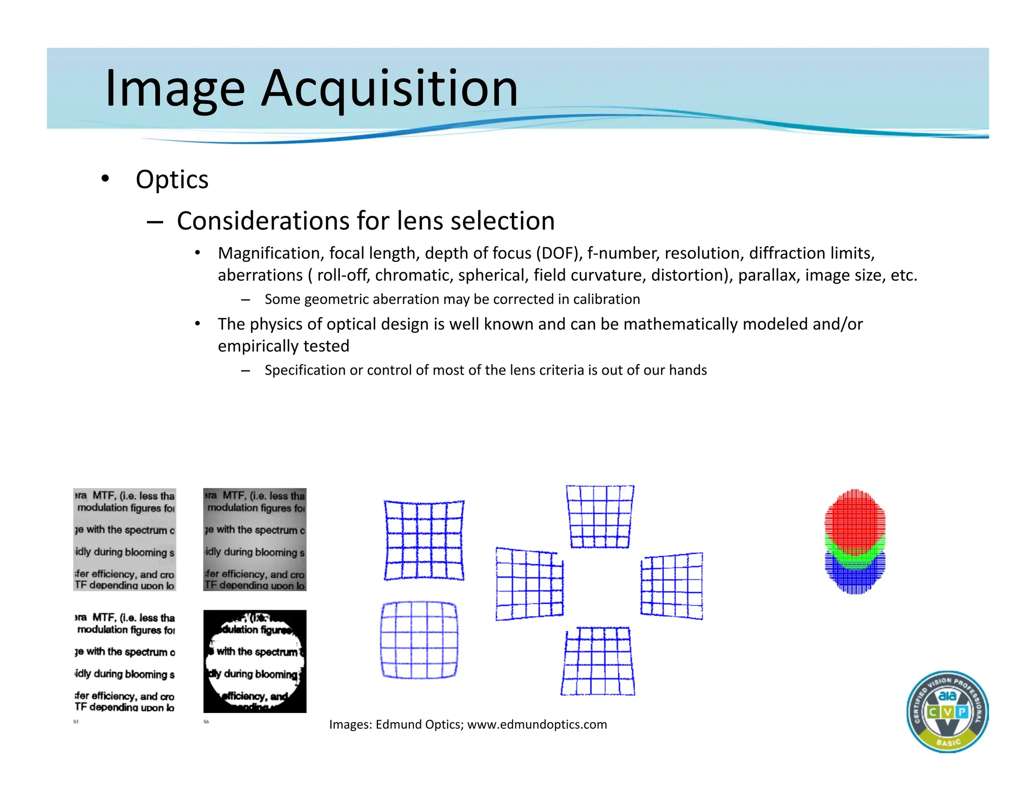
–Considerations for lens selection
• Magnification, focal length, depth of focus (DOF), f‐number, resolution, diffraction limits,
aberrations ( roll‐off, chromatic, spherical, field curvature, distortion), parallax, image size, etc.
– Some geometric aberration may be corrected in calibration
• The physics of optical design is well known and can be mathematically modeled and/or
empirically tested
– Specification or control of most of the lens criteria is out of our hands
S5 S6
Images: Edmund Optics; www.edmundoptics.com
29.
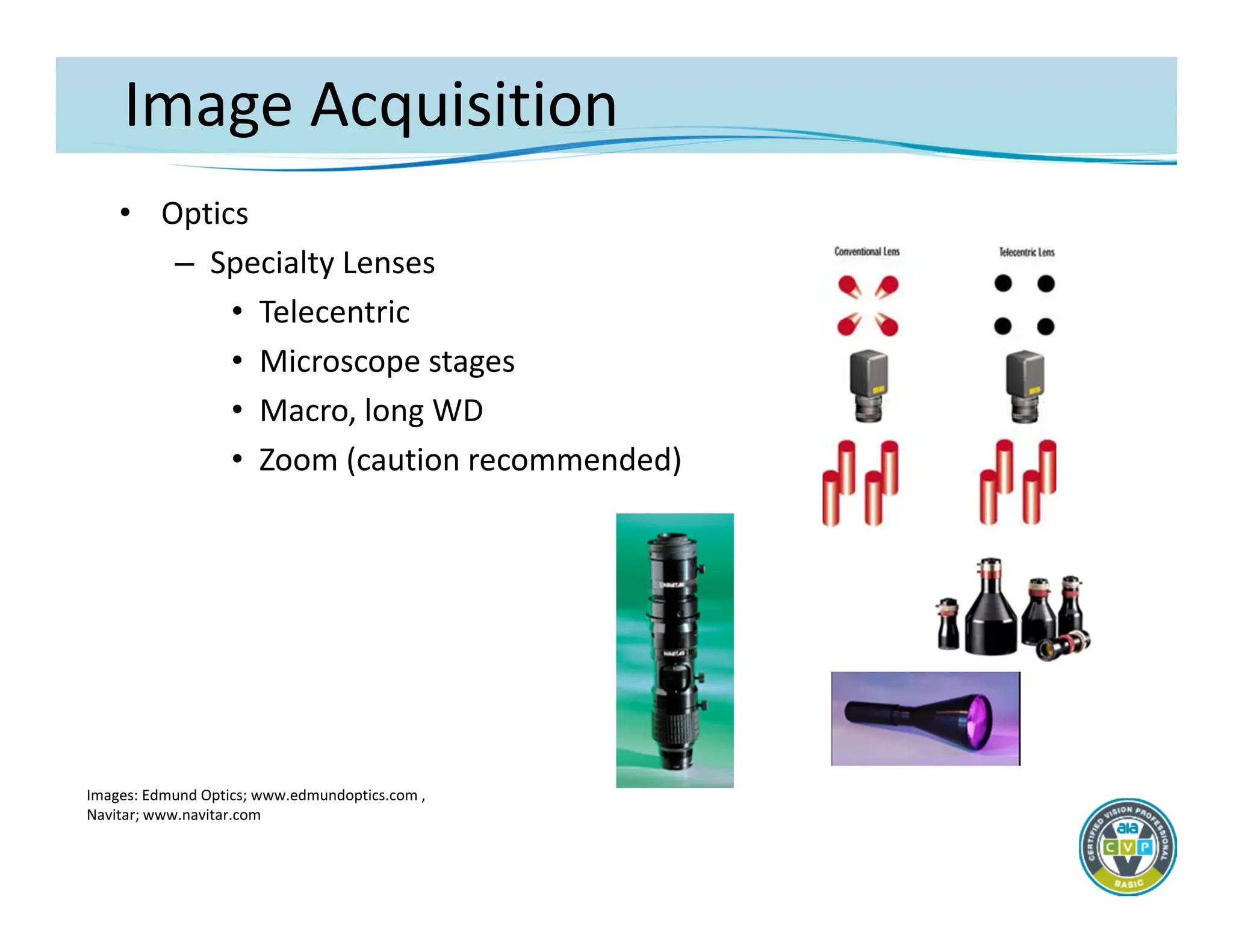
Image Acquisition
• Optics
–Considerations for lens selection
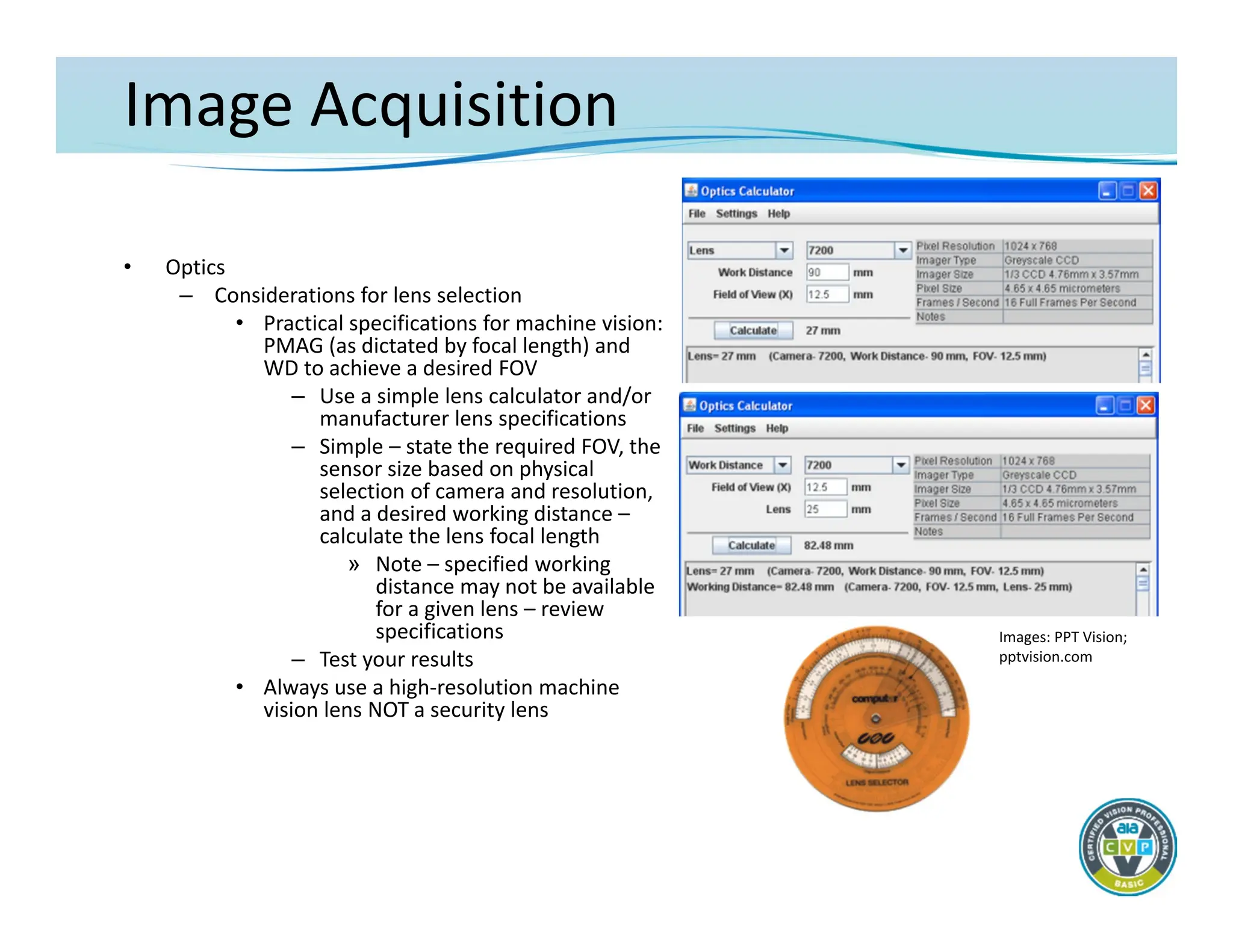
• Practical specifications for machine vision:
PMAG (as dictated by focal length) and
WD to achieve a desired FOV
– Use a simple lens calculator and/or
manufacturer lens specifications
– Simple – state the required FOV, the
sensor size based on physical
selection of camera and resolution,
and a desired working distance –
calculate the lens focal length
» Note – specified working
distance may not be available
for a given lens – review
specifications
– Test your results
• Always use a high‐resolution machine
vision lens NOT a security lens
Images: PPT Vision;
pptvision.com
30.
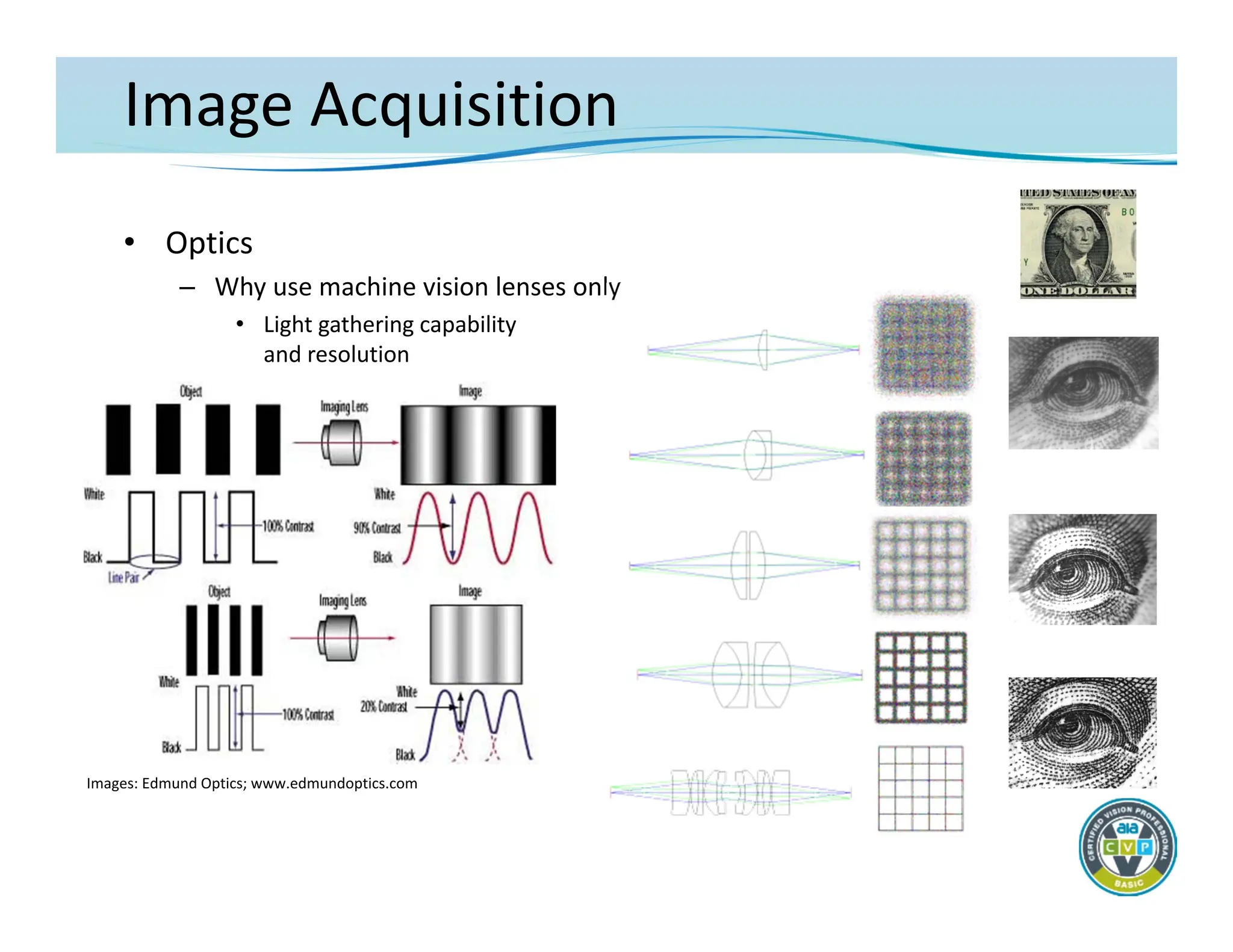
Image Acquisition
• Optics
–Why use machine vision lenses only
• Light gathering capability
and resolution
Images: Edmund Optics; www.edmundoptics.com
Image Acquisition
• Lighting
–Science or art???
– Correct lighting must
• Highlight features to be detected relative to background
• Create repeatable images regardless of part variation
– Incorrect lighting will put the
success/reliability/repeatability/ease‐of‐use of the vision
application at risk
• Machine vision cameras and software algorithms CANNOT
make up for inadequate illumination techniques
33.
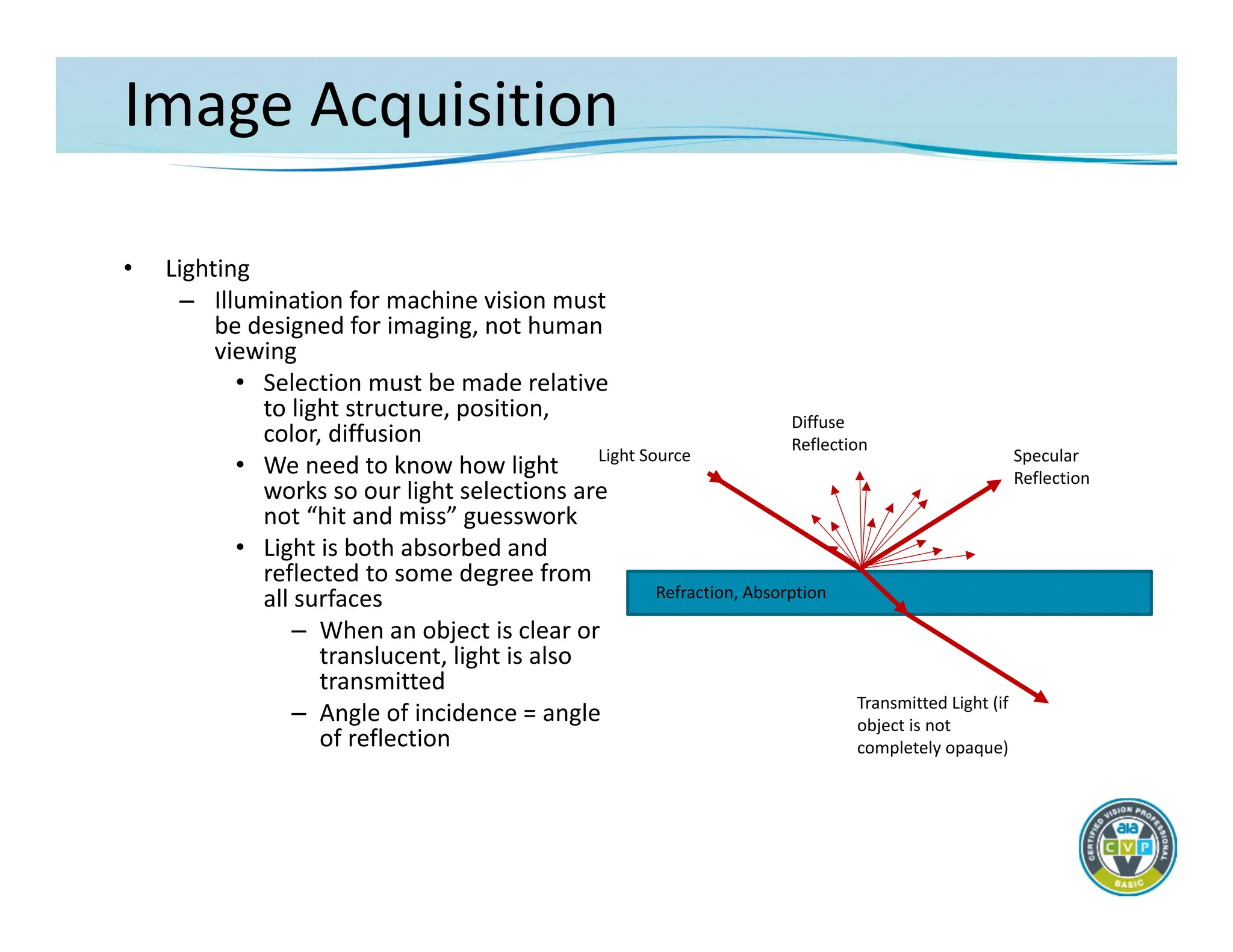
Image Acquisition
• Lighting
–Illumination for machine vision must
be designed for imaging, not human
viewing
• Selection must be made relative
to light structure, position,
color, diffusion
• We need to know how light
works so our light selections are
not “hit and miss” guesswork
• Light is both absorbed and
reflected to some degree from
all surfaces
– When an object is clear or
translucent, light is also
transmitted
– Angle of incidence = angle
of reflection
Light Source Specular
Reflection
Transmitted Light (if
object is not
completely opaque)
Diffuse
Reflection
Refraction, Absorption
34.
Image Acquisition
• Lighting
–Dedicated lighting must be used for machine vision with few
exceptions.
– Where feasible, LED illumination is the best source
• Long life with minimal degradation of intensity
• Able to be structured into a variety of shapes
– May be directional or diffuse
• May be strobed at very high duty cycles and overdriven to many
times nominal current specifications
• Available in many visible and non‐visible colors
– Other sources – fluorescent, fiber‐optics
• Fluorescent – bright and highly diffuse but can be inconsistent
• Fiber optic – glass/plastic fibers delivering light from halogen,
tungsten‐halogen or xenon source, bright, shapeable, focused
35.
Image Acquisition
• Lighting
–Lighting Techniques
• The goal of lighting for machine vision applications usually is
to maximize the contrast (grayscale difference) between
features of interest and surrounding background
• Techniques are categorized generally by the direction of the
illumination source
– Most may be achieved with different sources
36.
Image Acquisition
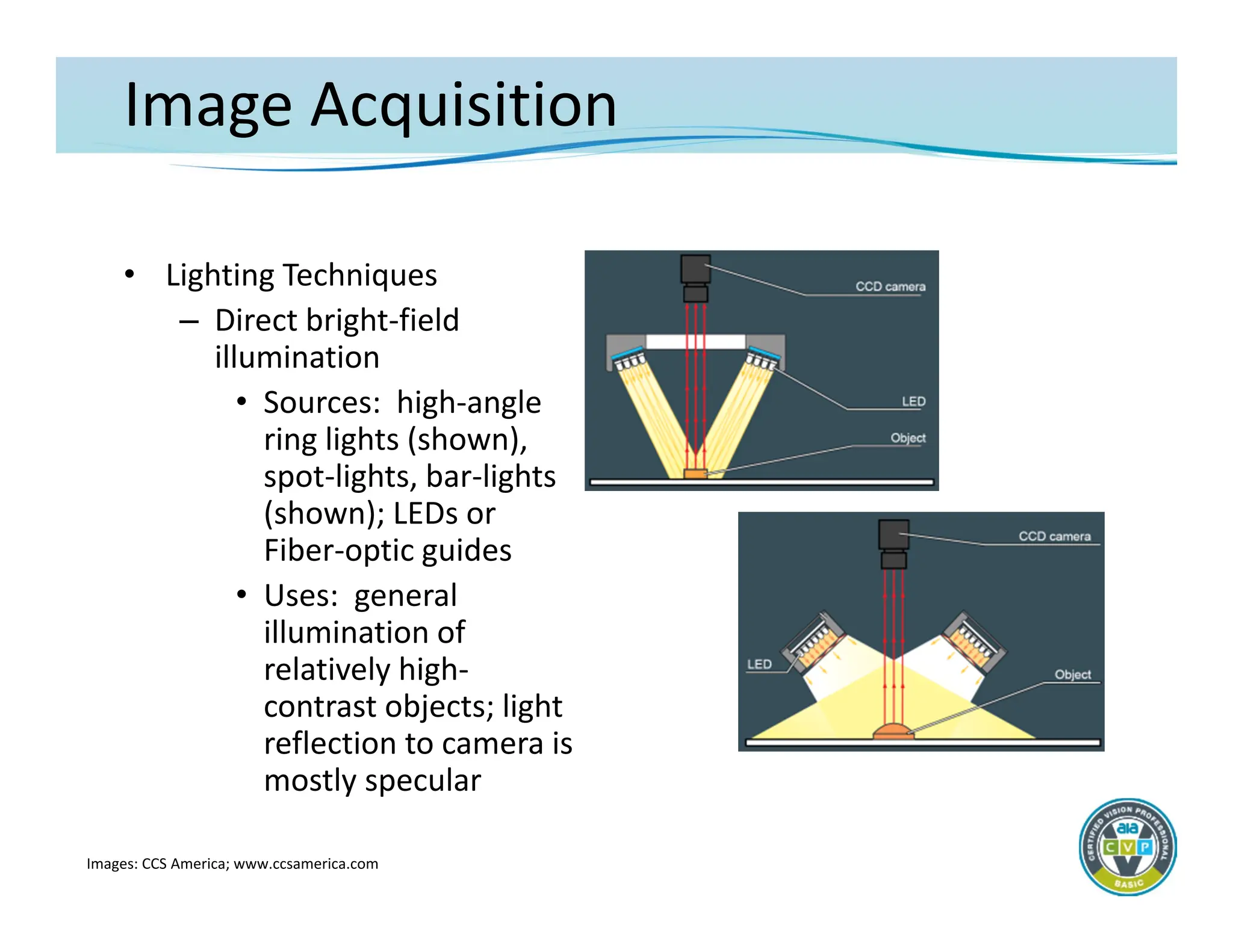
• LightingTechniques
– Direct bright‐field
illumination
• Sources: high‐angle
ring lights (shown),
spot‐lights, bar‐lights
(shown); LEDs or
Fiber‐optic guides
• Uses: general
illumination of
relatively high‐
contrast objects; light
reflection to camera is
mostly specular
Images: CCS America; www.ccsamerica.com
37.
Image Acquisition
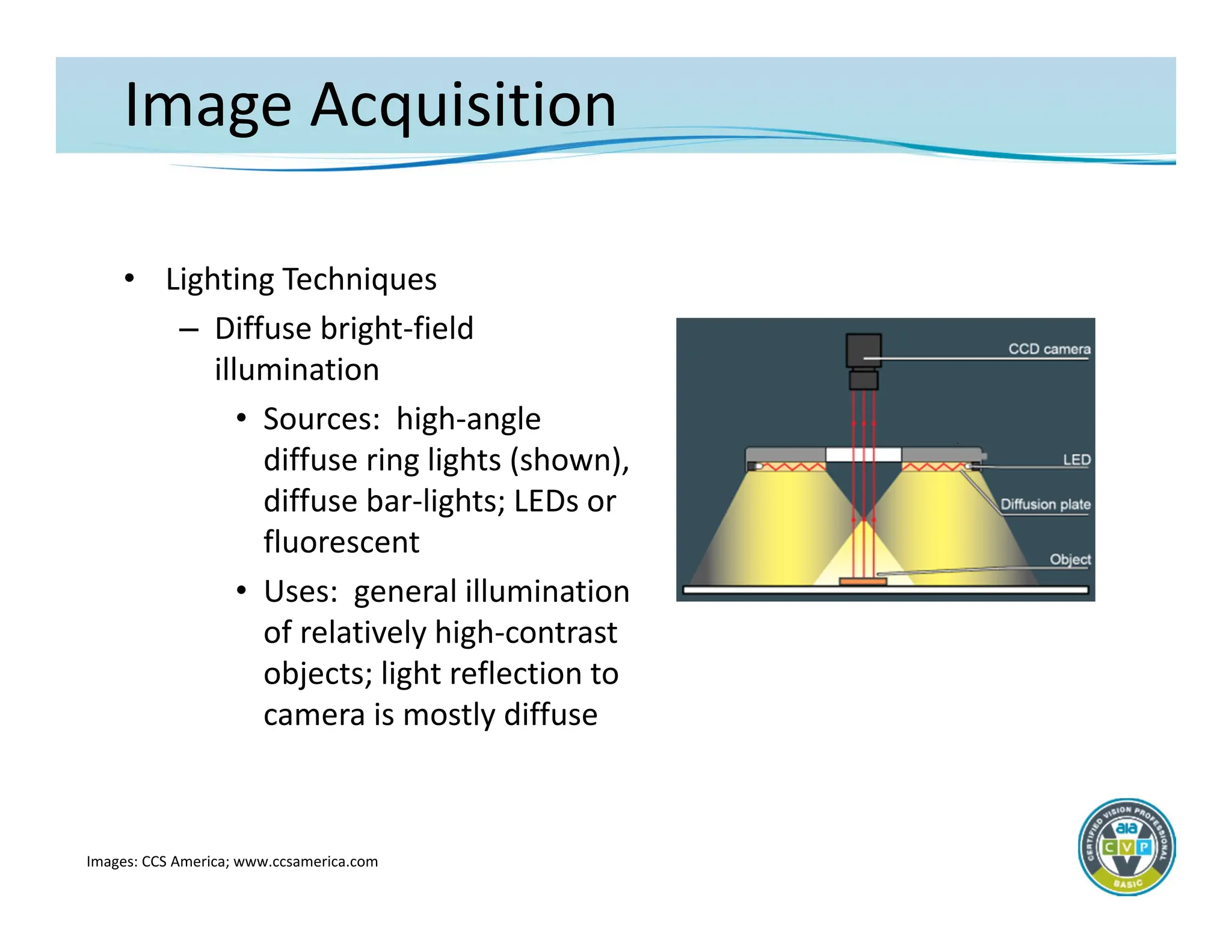
• LightingTechniques
– Diffuse bright‐field
illumination
• Sources: high‐angle
diffuse ring lights (shown),
diffuse bar‐lights; LEDs or
fluorescent
• Uses: general illumination
of relatively high‐contrast
objects; light reflection to
camera is mostly diffuse
Images: CCS America; www.ccsamerica.com
38.
Image Acquisition
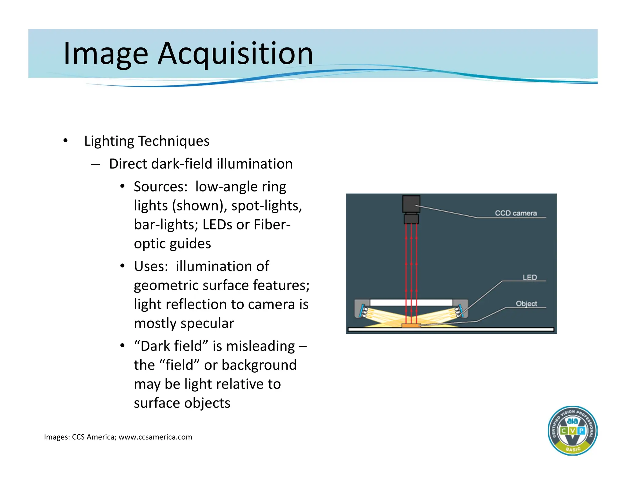
• LightingTechniques
– Direct dark‐field illumination
• Sources: low‐angle ring
lights (shown), spot‐lights,
bar‐lights; LEDs or Fiber‐
optic guides
• Uses: illumination of
geometric surface features;
light reflection to camera is
mostly specular
• “Dark field” is misleading –
the “field” or background
may be light relative to
surface objects
Images: CCS America; www.ccsamerica.com
39.
Image Acquisition
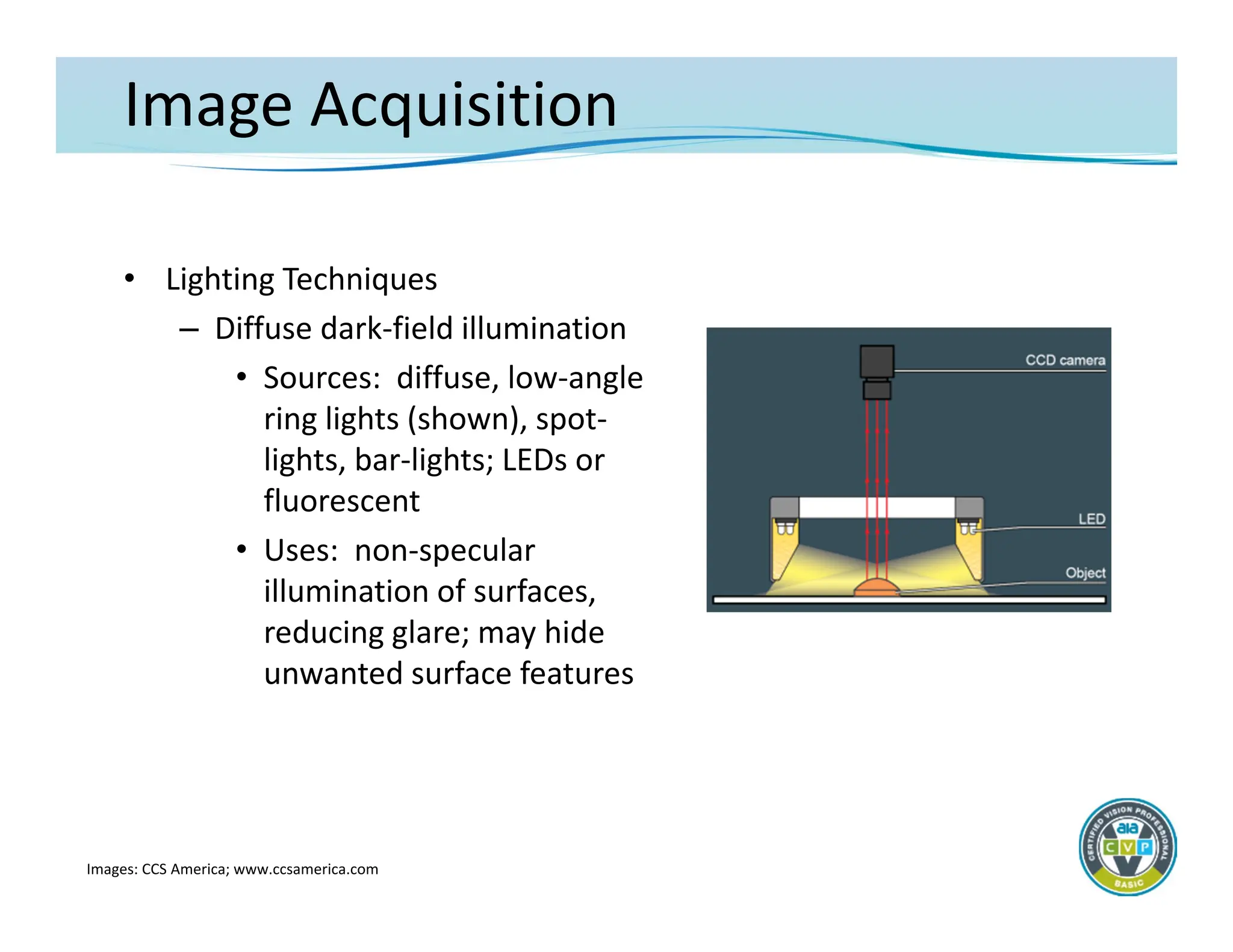
• LightingTechniques
– Diffuse dark‐field illumination
• Sources: diffuse, low‐angle
ring lights (shown), spot‐
lights, bar‐lights; LEDs or
fluorescent
• Uses: non‐specular
illumination of surfaces,
reducing glare; may hide
unwanted surface features
Images: CCS America; www.ccsamerica.com
40.
Image Acquisition
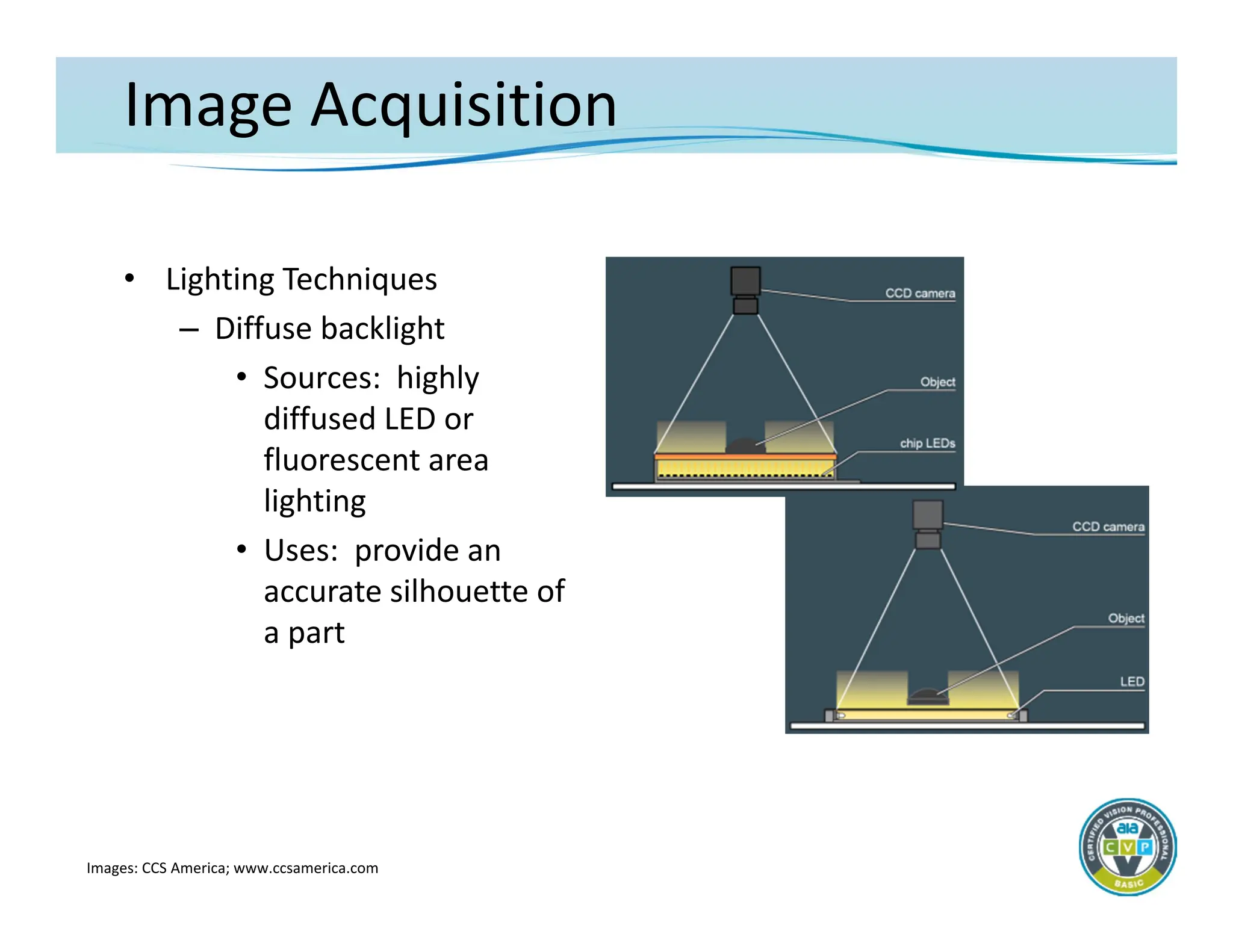
• LightingTechniques
– Diffuse backlight
• Sources: highly
diffused LED or
fluorescent area
lighting
• Uses: provide an
accurate silhouette of
a part
Images: CCS America; www.ccsamerica.com
41.
Image Acquisition
• LightingTechniques
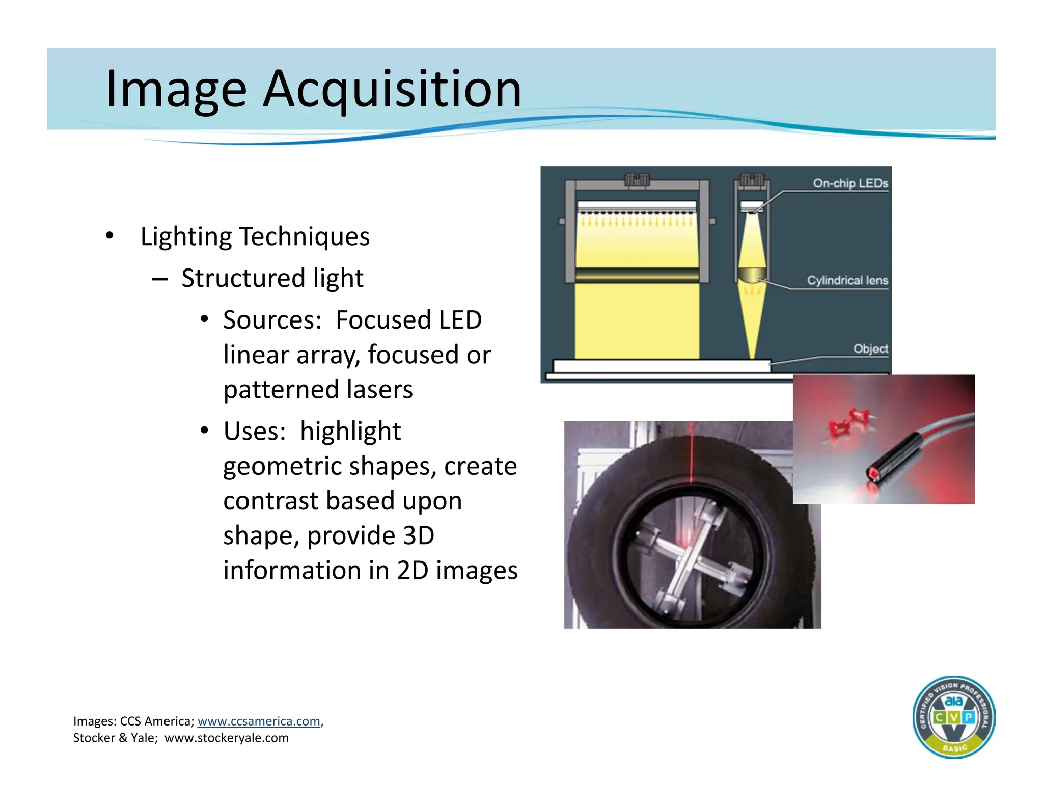
– Structured light
• Sources: Focused LED
linear array, focused or
patterned lasers
• Uses: highlight
geometric shapes, create
contrast based upon
shape, provide 3D
information in 2D images
Images: CCS America; www.ccsamerica.com,
Stocker & Yale; www.stockeryale.com
42.
Image Acquisition
• LightingTechniques
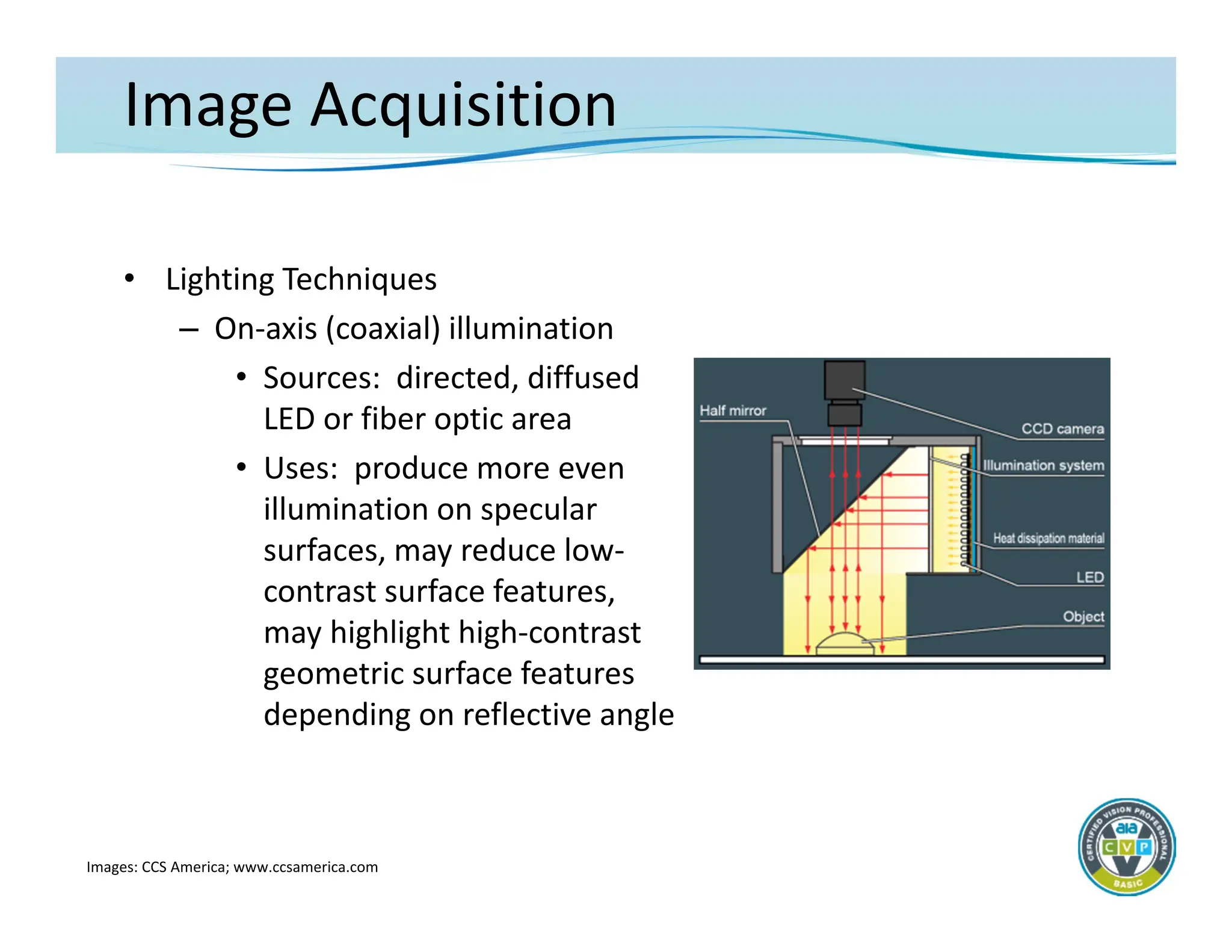
– On‐axis (coaxial) illumination
• Sources: directed, diffused
LED or fiber optic area
• Uses: produce more even
illumination on specular
surfaces, may reduce low‐
contrast surface features,
may highlight high‐contrast
geometric surface features
depending on reflective angle
Images: CCS America; www.ccsamerica.com
43.
Image Acquisition
• LightingTechniques
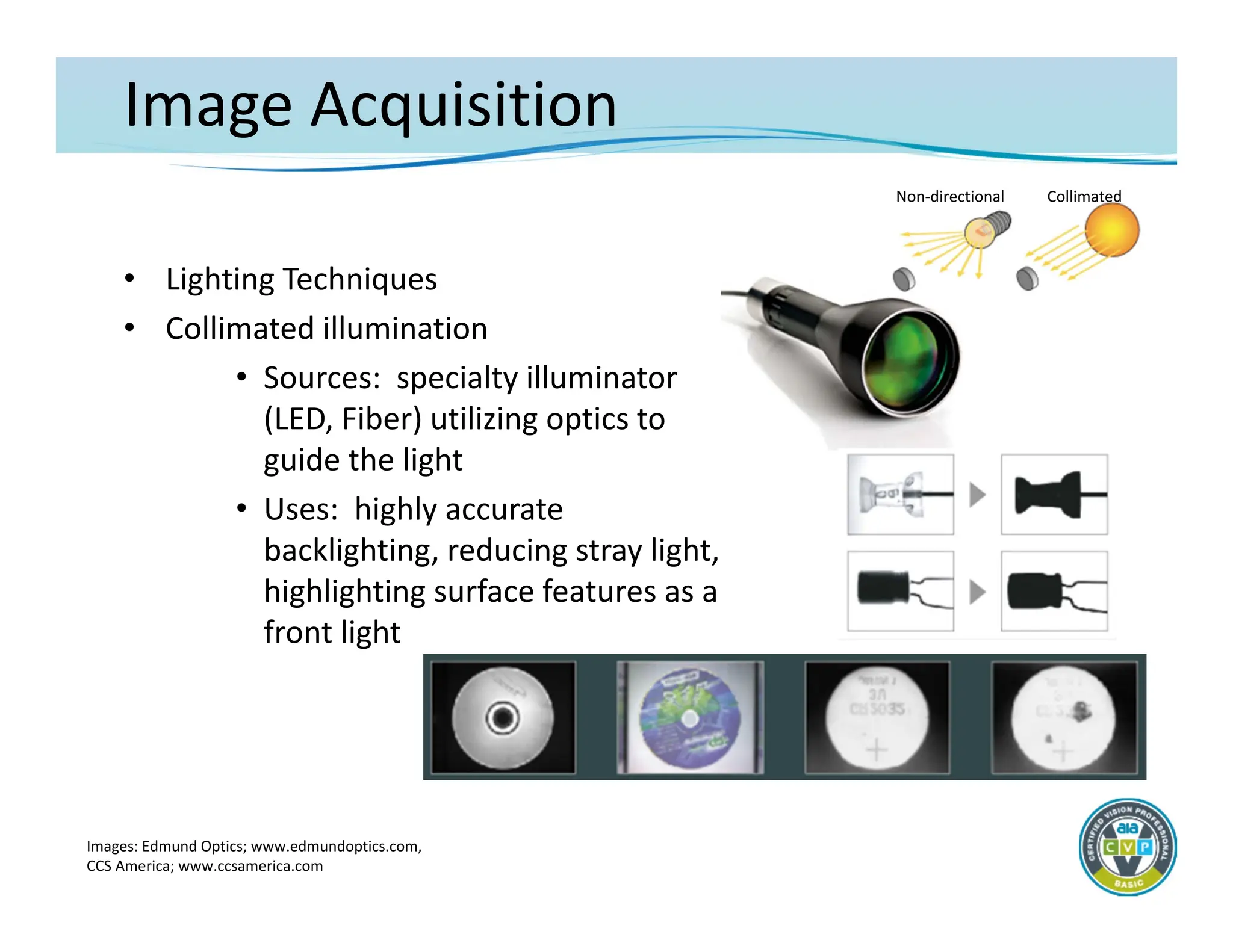
• Collimated illumination
• Sources: specialty illuminator
(LED, Fiber) utilizing optics to
guide the light
• Uses: highly accurate
backlighting, reducing stray light,
highlighting surface features as a
front light
Images: Edmund Optics; www.edmundoptics.com,
CCS America; www.ccsamerica.com
Non‐directional Collimated
44.
Image Acquisition
• LightingTechniques
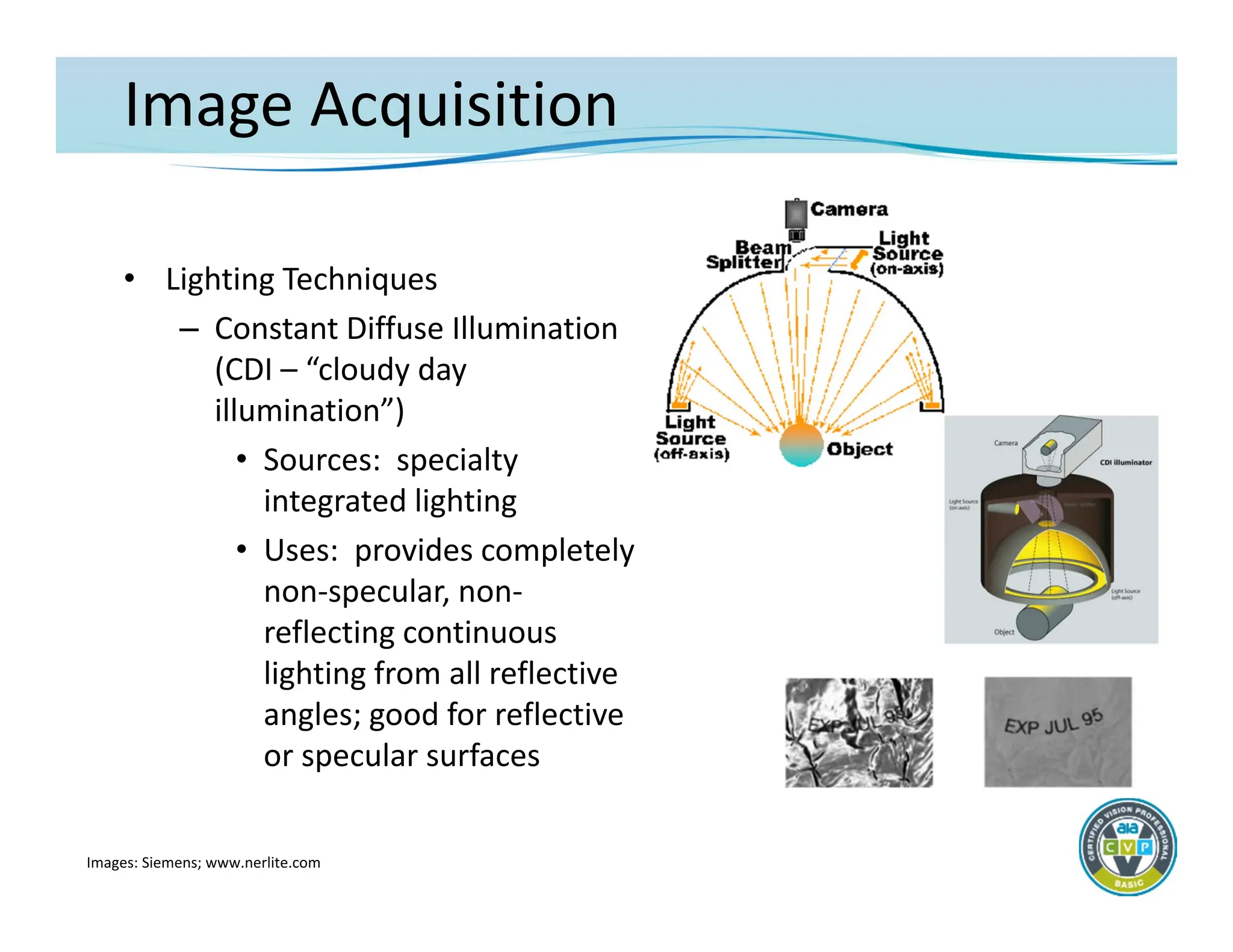
– Constant Diffuse Illumination
(CDI – “cloudy day
illumination”)
• Sources: specialty
integrated lighting
• Uses: provides completely
non‐specular, non‐
reflecting continuous
lighting from all reflective
angles; good for reflective
or specular surfaces
Images: Siemens; www.nerlite.com
45.
Image Acquisition
• LightingTechniques
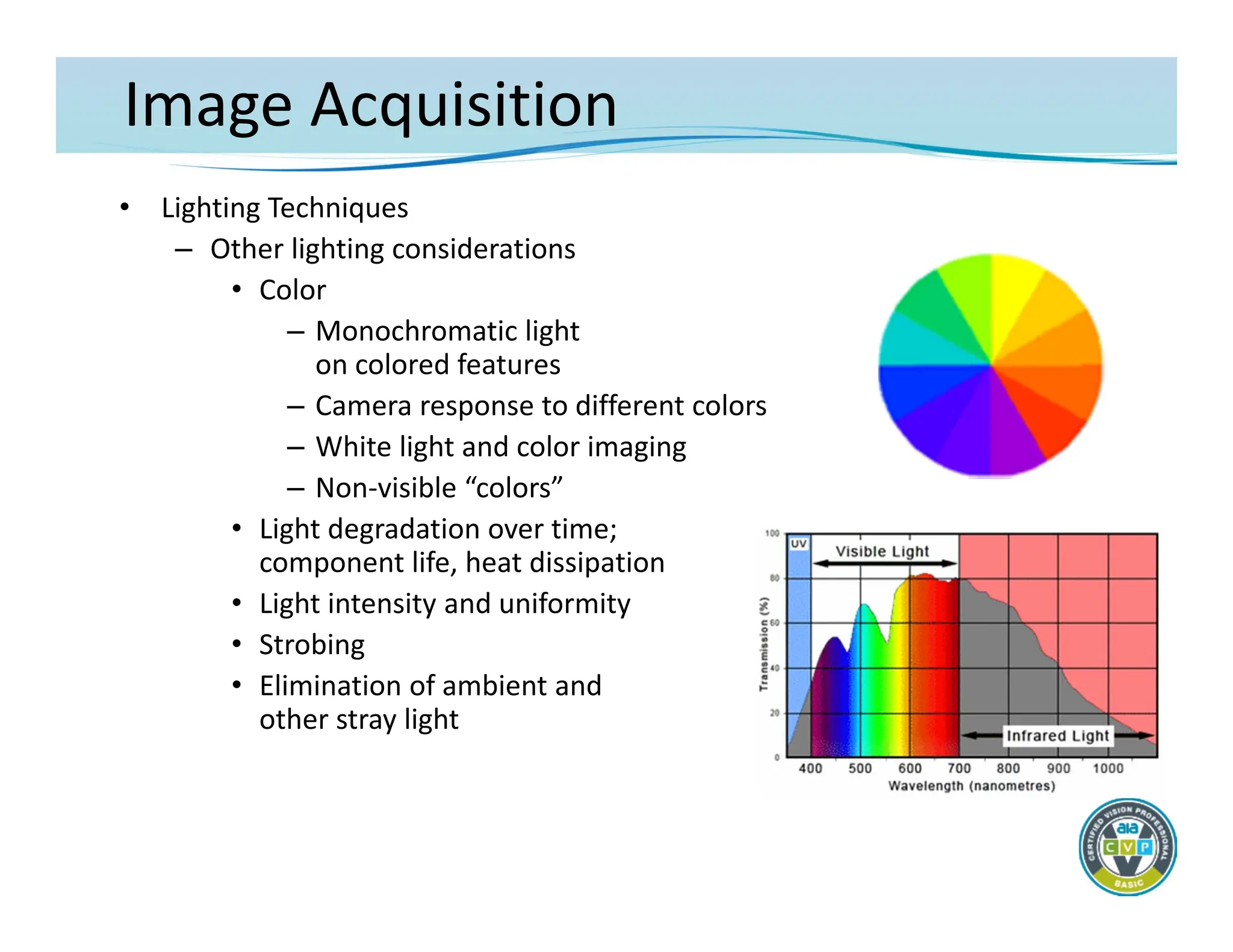
– Other lighting considerations
• Color
– Monochromatic light
on colored features
– Camera response to different colors
– White light and color imaging
– Non‐visible “colors”
• Light degradation over time;
component life, heat dissipation
• Light intensity and uniformity
• Strobing
• Elimination of ambient and
other stray light
46.
IMAGE ANALYSIS
The Fundamentalsof Machine Vision
– Machine Vision Software
– General Machine Vision Algorithms
Acquisition
Analysis
Integration
47.
Image Analysis
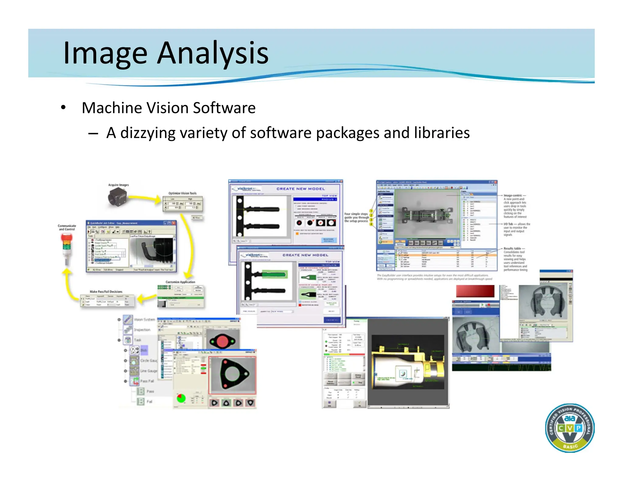
• MachineVision Software
– Machine vision software drives component capability, reliability,
and usability
– Main machine vision component differentiation is in the
software implementation
• Available image processing and analysis tools
• Ability to manipulate imaging and system hardware
• Method for inspection task configuration/programming
• Interface to hardware, communications and I/O
• Operator interface and display capability
– Often, system software complexity increases with system
capability
– AND greater ease of use usually is at the expense of some
algorithmic and/or configuration capabilities
Image Analysis
• MachineVision Software
– What’s Important
• Sufficient algorithm depth and capability to perform the
required inspection tasks
– Consider:
» Speed of processing
» Level of tool parameterization
» Ease with which tools can be combined
• Adequate flexibility in the process configuration to service
the automation requirements
• Enough I/O and communications capability to interface with
existing automation as necessary
• Appropriate software/computer interfacing to implement an
operator interface as needed for the application
50.
Image Analysis
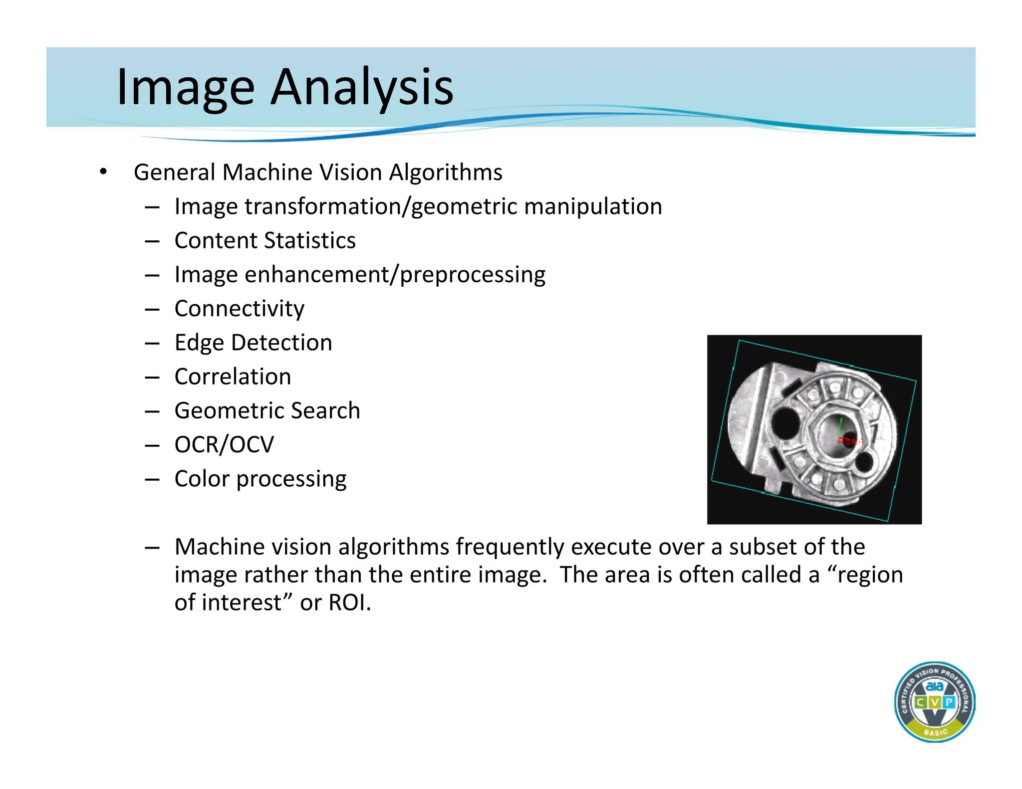
• GeneralMachine Vision Algorithms
– Image transformation/geometric manipulation
– Content Statistics
– Image enhancement/preprocessing
– Connectivity
– Edge Detection
– Correlation
– Geometric Search
– OCR/OCV
– Color processing
– Machine vision algorithms frequently execute over a subset of the
image rather than the entire image. The area is often called a “region
of interest” or ROI.
Image Analysis
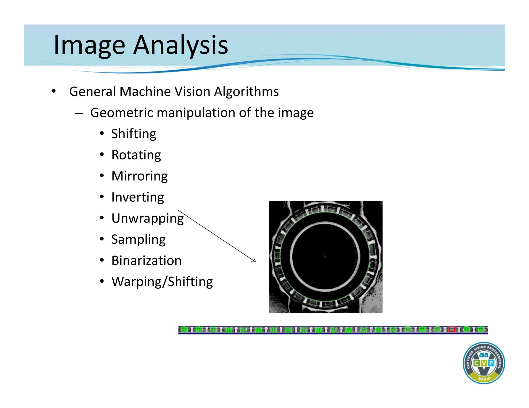
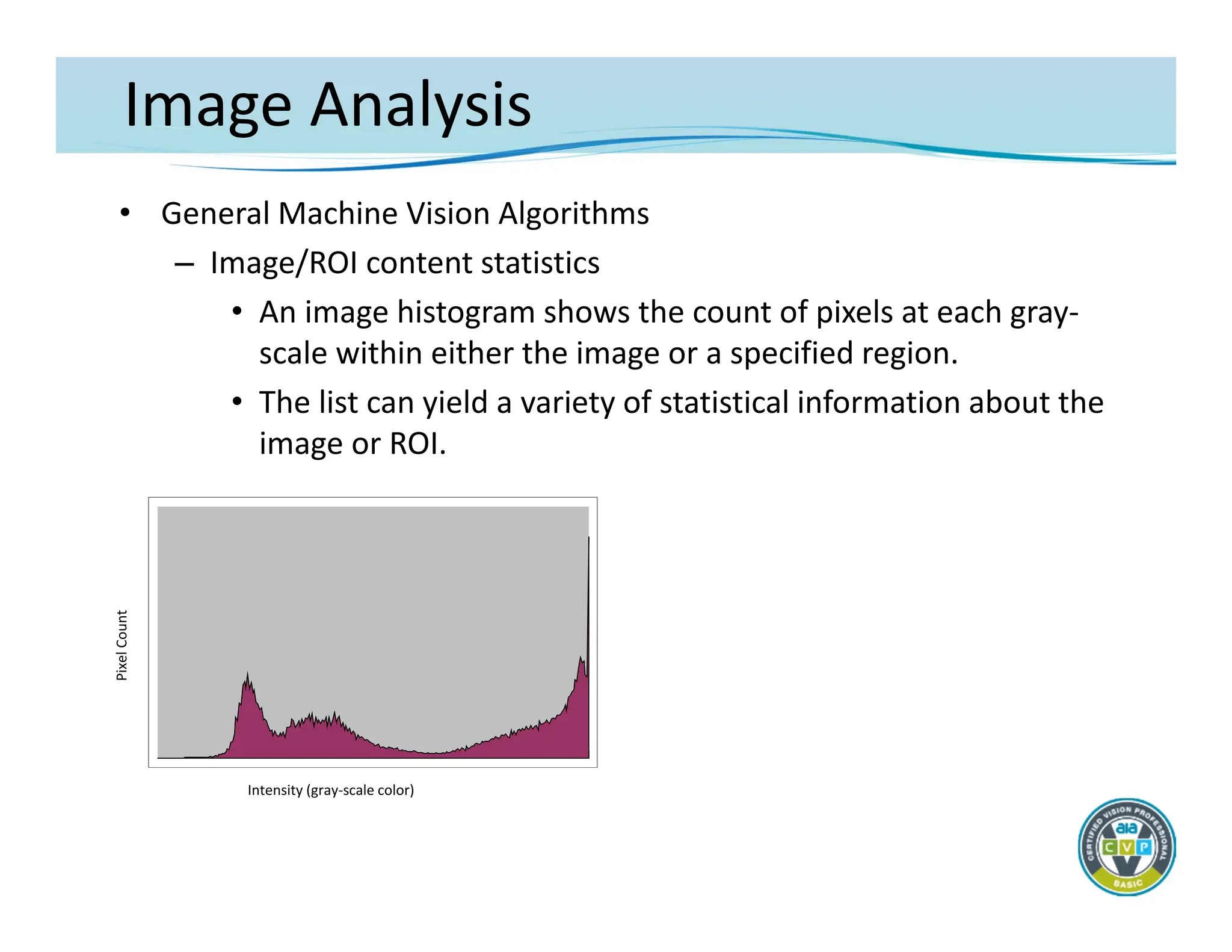
• GeneralMachine Vision Algorithms
– Image/ROI content statistics
• An image histogram shows the count of pixels at each gray‐
scale within either the image or a specified region.
• The list can yield a variety of statistical information about the
image or ROI.
Pixel
Count
Intensity (gray‐scale color)
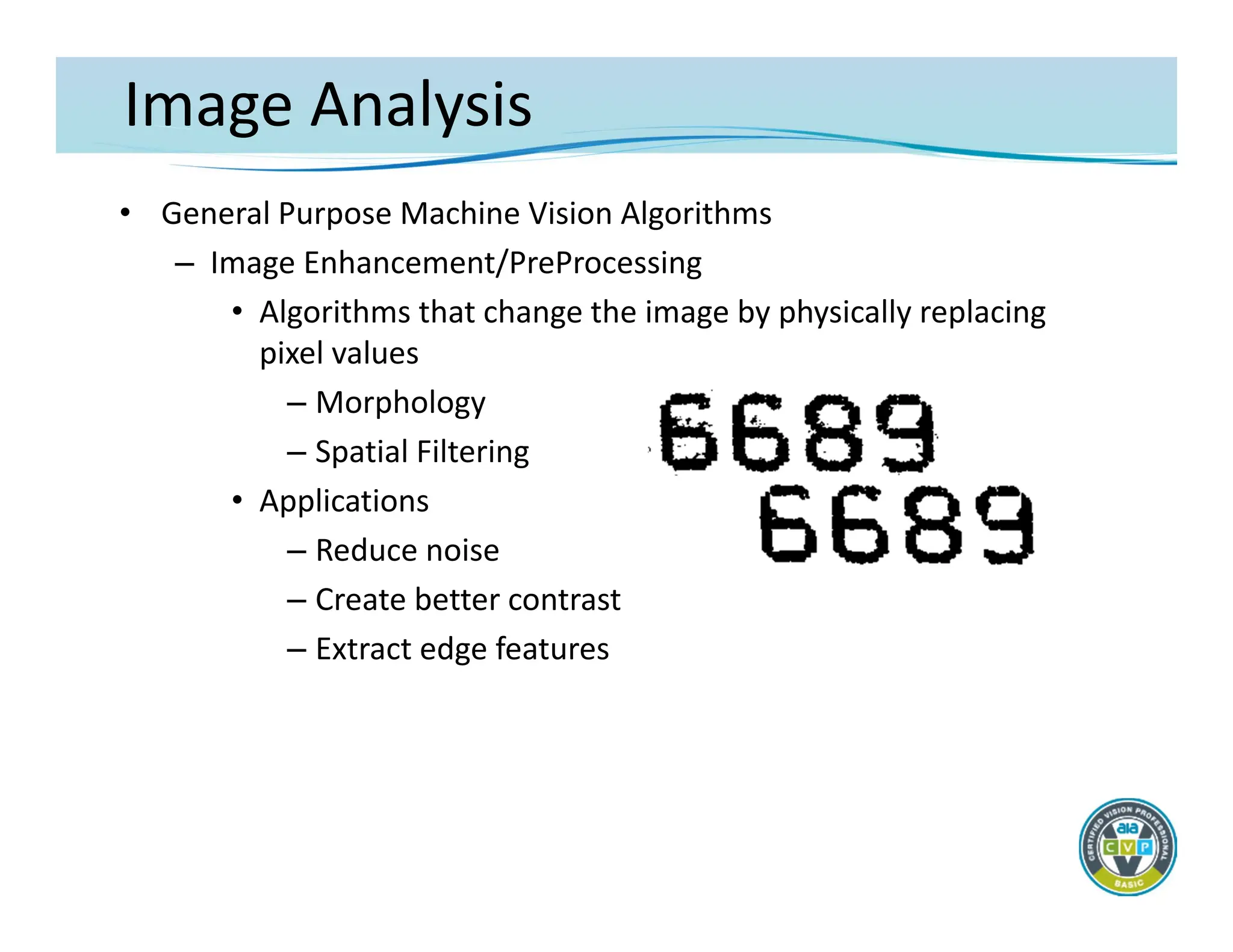
Image Analysis
• GeneralPurpose Machine Vision Algorithms
– Image Enhancement/PreProcessing
• Algorithms that change the image by physically replacing
pixel values
– Morphology
– Spatial Filtering
• Applications
– Reduce noise
– Create better contrast
– Extract edge features
55.
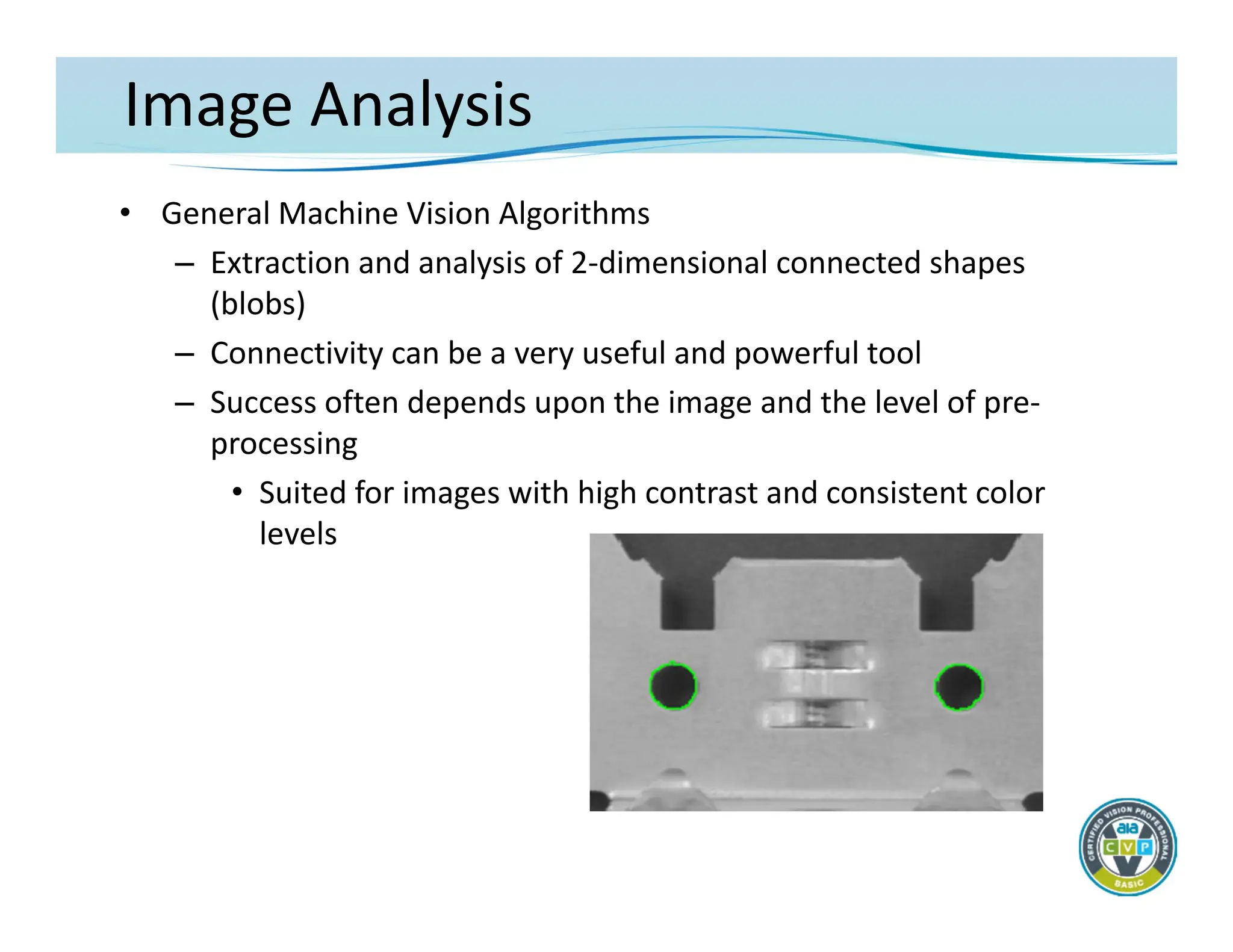
Image Analysis
• GeneralMachine Vision Algorithms
– Extraction and analysis of 2‐dimensional connected shapes
(blobs)
– Connectivity can be a very useful and powerful tool
– Success often depends upon the image and the level of pre‐
processing
• Suited for images with high contrast and consistent color
levels
56.
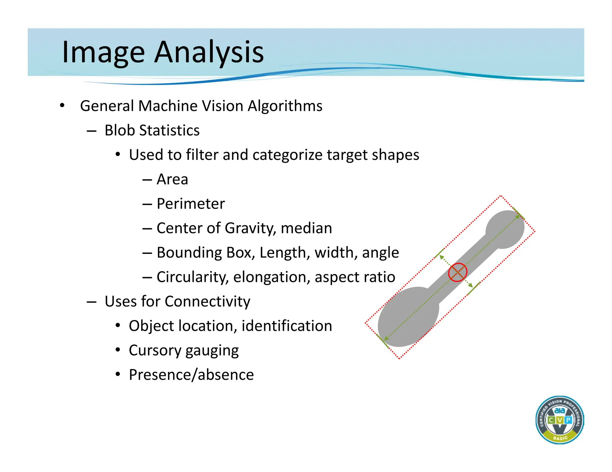
Image Analysis
• GeneralMachine Vision Algorithms
– Blob Statistics
• Used to filter and categorize target shapes
– Area
– Perimeter
– Center of Gravity, median
– Bounding Box, Length, width, angle
– Circularity, elongation, aspect ratio
– Uses for Connectivity
• Object location, identification
• Cursory gauging
• Presence/absence
57.
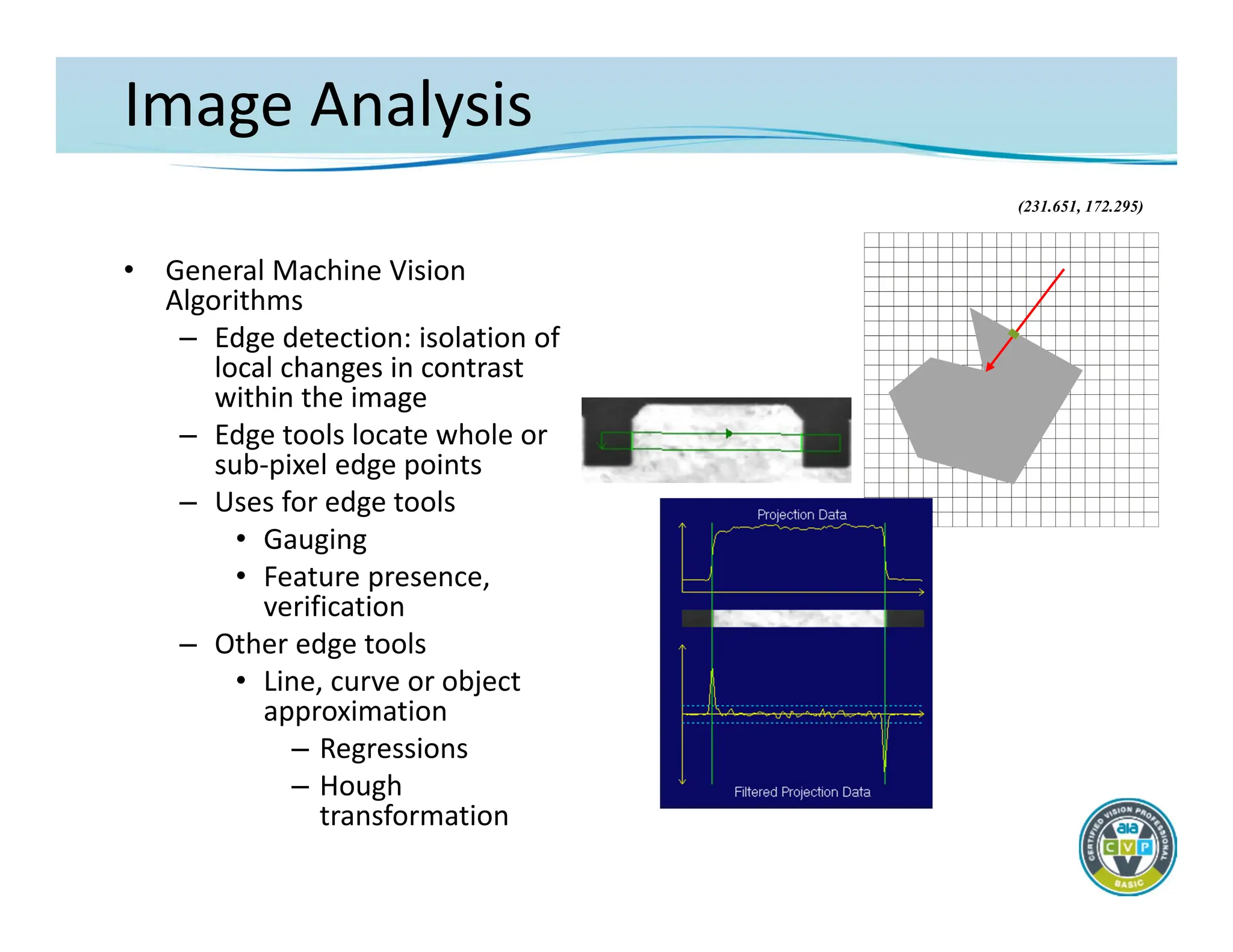
Image Analysis
• GeneralMachine Vision
Algorithms
– Edge detection: isolation of
local changes in contrast
within the image
– Edge tools locate whole or
sub‐pixel edge points
– Uses for edge tools
• Gauging
• Feature presence,
verification
– Other edge tools
• Line, curve or object
approximation
– Regressions
– Hough
transformation
(231.651, 172.295)
Image Analysis
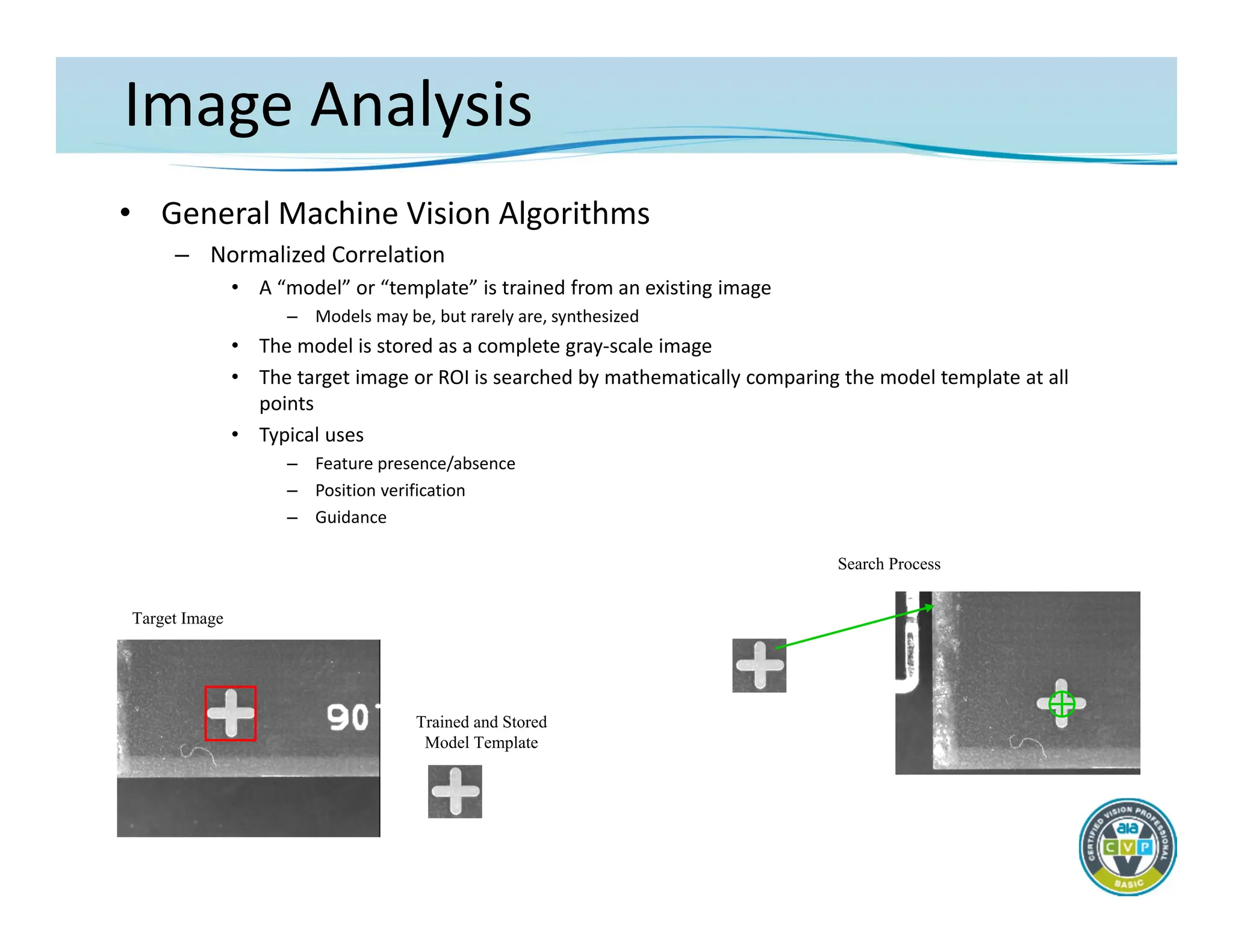
• GeneralMachine Vision Algorithms
– Normalized Correlation
• A “model” or “template” is trained from an existing image
– Models may be, but rarely are, synthesized
• The model is stored as a complete gray‐scale image
• The target image or ROI is searched by mathematically comparing the model template at all
points
• Typical uses
– Feature presence/absence
– Position verification
– Guidance
Target Image
Trained and Stored
Model Template
Search Process
60.
Image Analysis
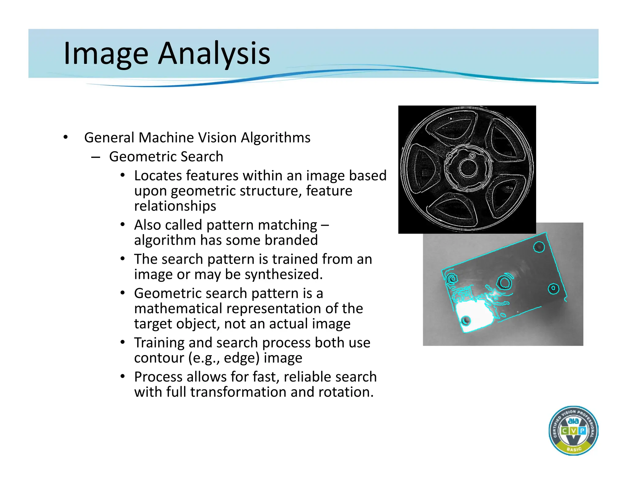
• GeneralMachine Vision Algorithms
– Geometric Search
• Locates features within an image based
upon geometric structure, feature
relationships
• Also called pattern matching –
algorithm has some branded
• The search pattern is trained from an
image or may be synthesized.
• Geometric search pattern is a
mathematical representation of the
target object, not an actual image
• Training and search process both use
contour (e.g., edge) image
• Process allows for fast, reliable search
with full transformation and rotation.
61.
Image Analysis
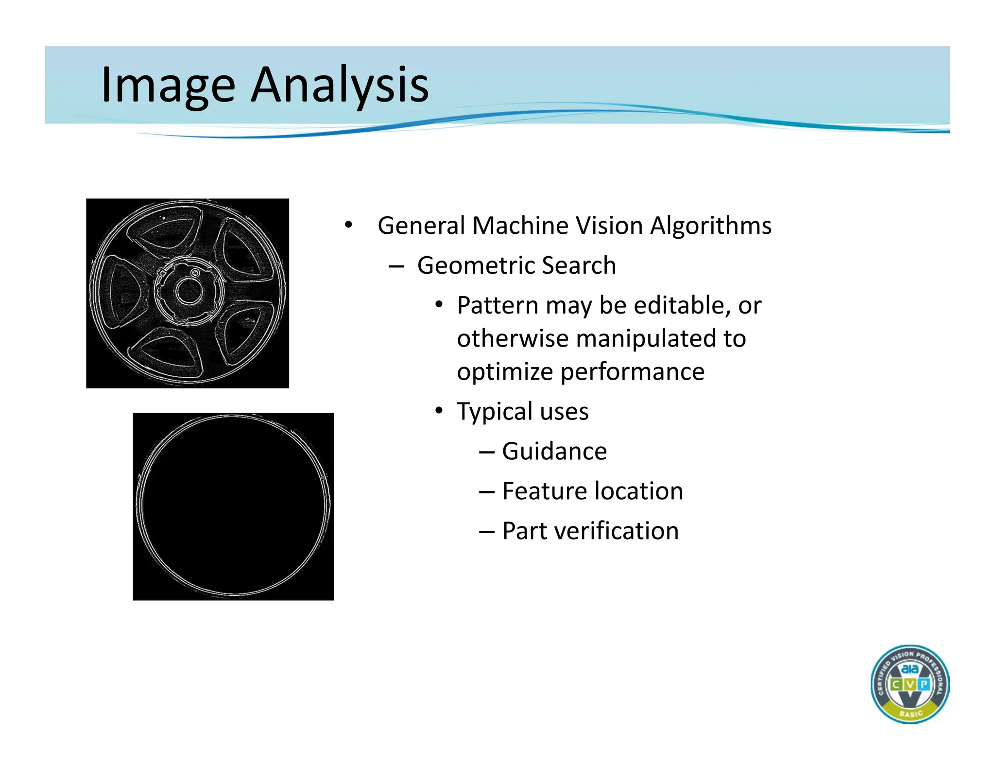
• GeneralMachine Vision Algorithms
– Geometric Search
• Pattern may be editable, or
otherwise manipulated to
optimize performance
• Typical uses
– Guidance
– Feature location
– Part verification
62.
Image Analysis
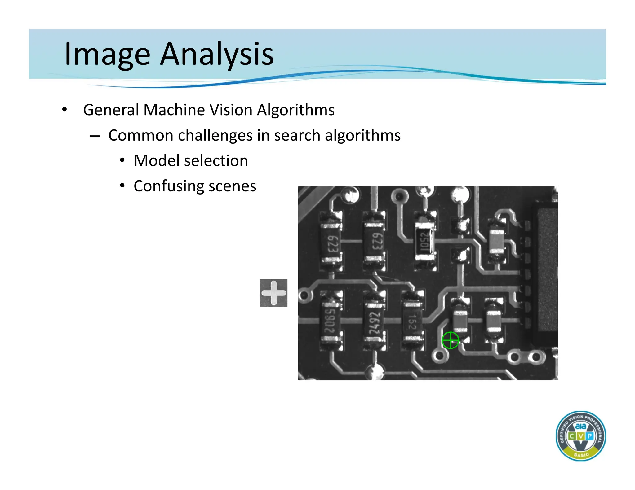
• GeneralMachine Vision Algorithms
– Common challenges in search algorithms
• Model selection
• Confusing scenes
63.
Image Analysis
• GeneralMachine Vision Algorithms
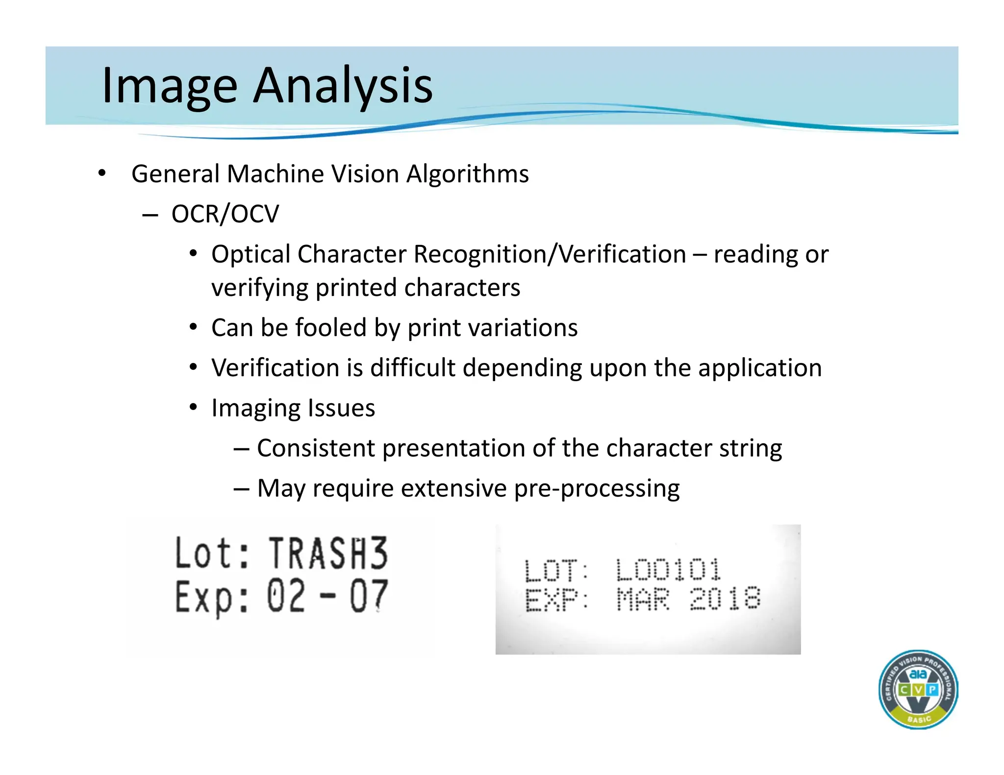
– OCR/OCV
• Optical Character Recognition/Verification – reading or
verifying printed characters
• Can be fooled by print variations
• Verification is difficult depending upon the application
• Imaging Issues
– Consistent presentation of the character string
– May require extensive pre‐processing
64.
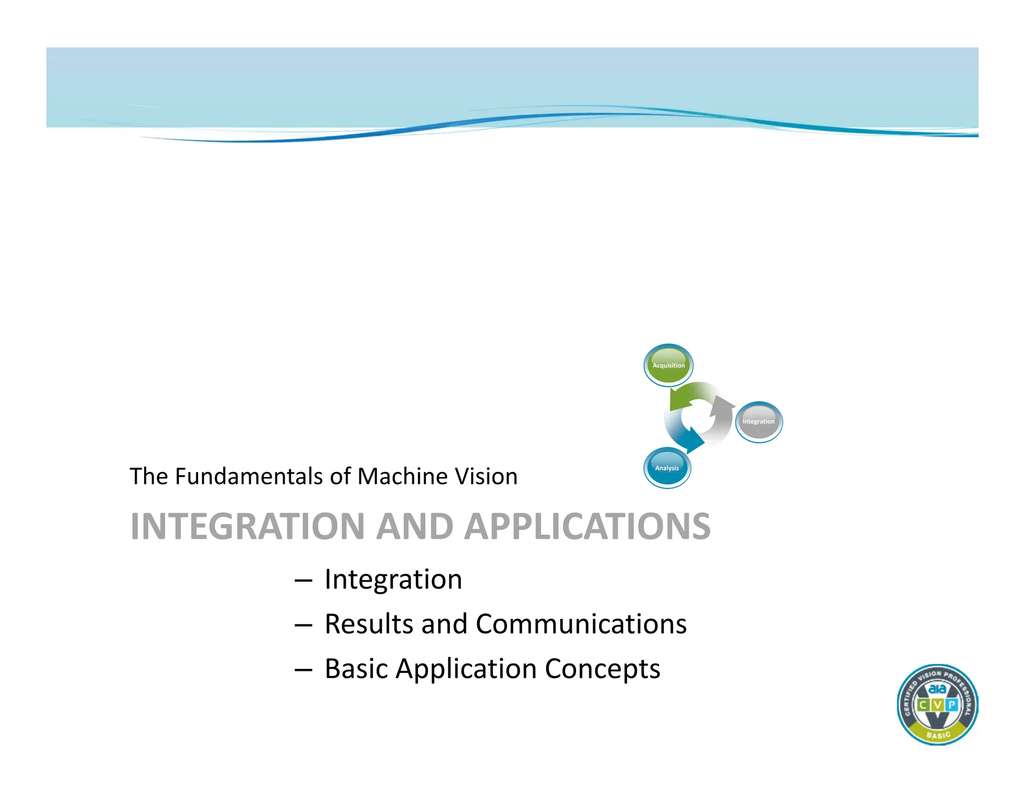
INTEGRATION AND APPLICATIONS
TheFundamentals of Machine Vision
– Integration
– Results and Communications
– Basic Application Concepts
Acquisition
Analysis
Integration
65.
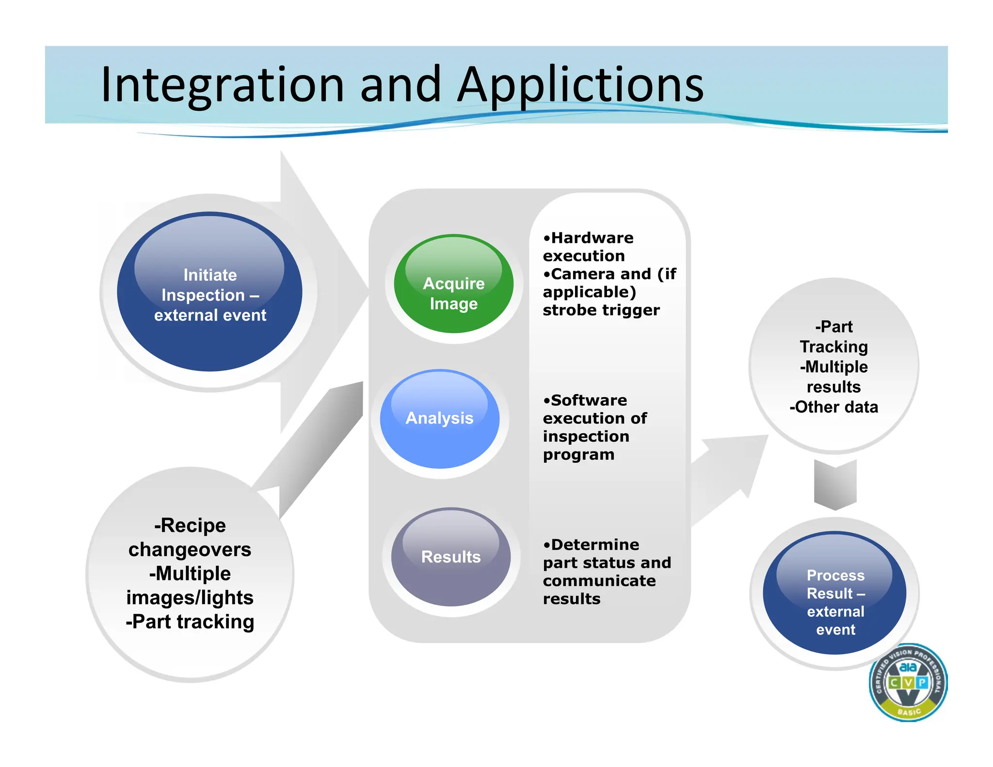
Integration and Applictions
•Hardware
execution
•Cameraand (if
applicable)
strobe trigger
•Software
execution of
inspection
program
•Determine
part status and
communicate
results
Initiate
Inspection –
external event
Results
Analysis
Acquire
Image
Process
Result –
external
event
-Recipe
changeovers
-Multiple
images/lights
-Part tracking
-Part
Tracking
-Multiple
results
-Other data
66.
Integration and Applications
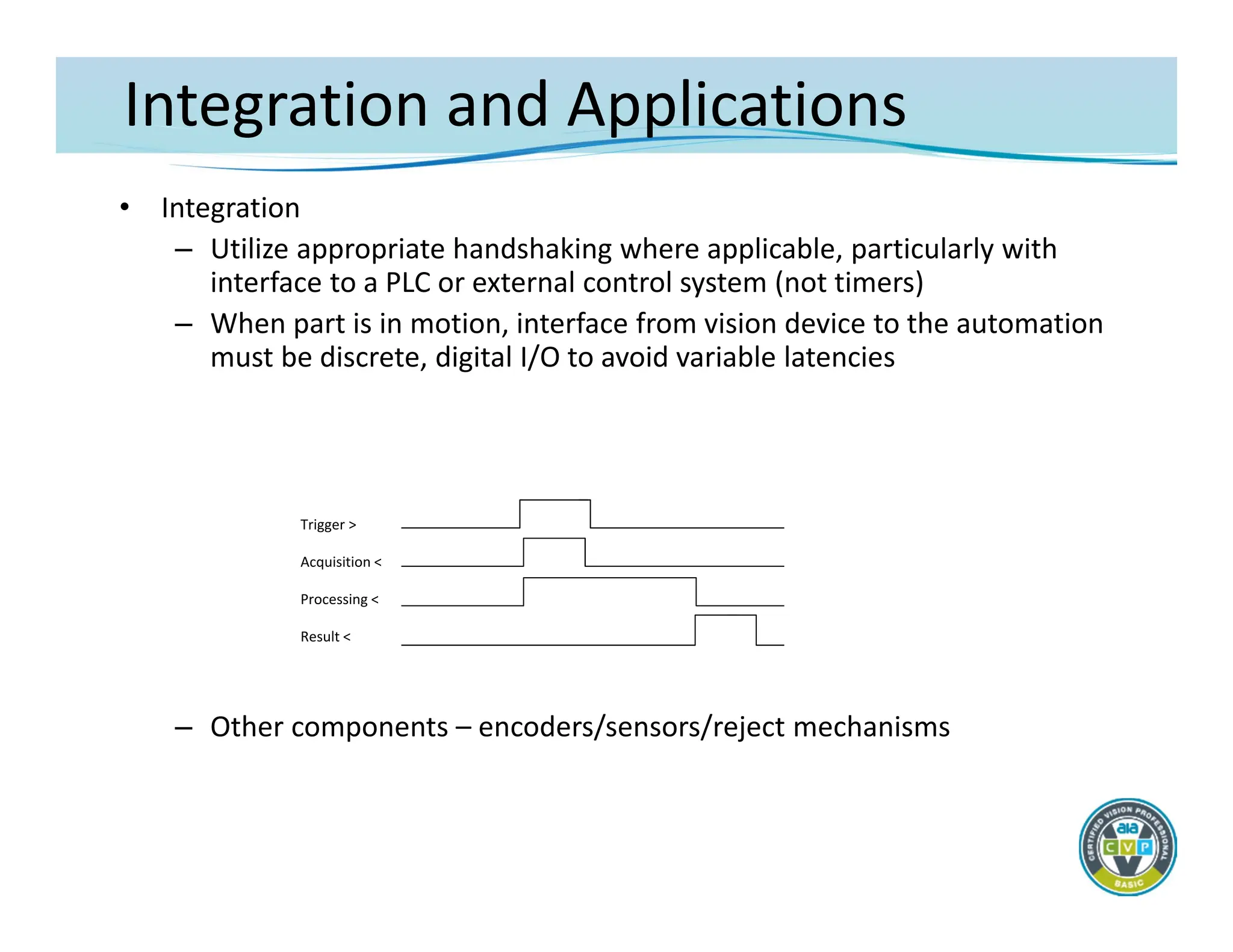
•Integration
– Utilize appropriate handshaking where applicable, particularly with
interface to a PLC or external control system (not timers)
– When part is in motion, interface from vision device to the automation
must be discrete, digital I/O to avoid variable latencies
– Other components – encoders/sensors/reject mechanisms
Trigger >
Acquisition <
Processing <
Result <
67.
Integration and Applications
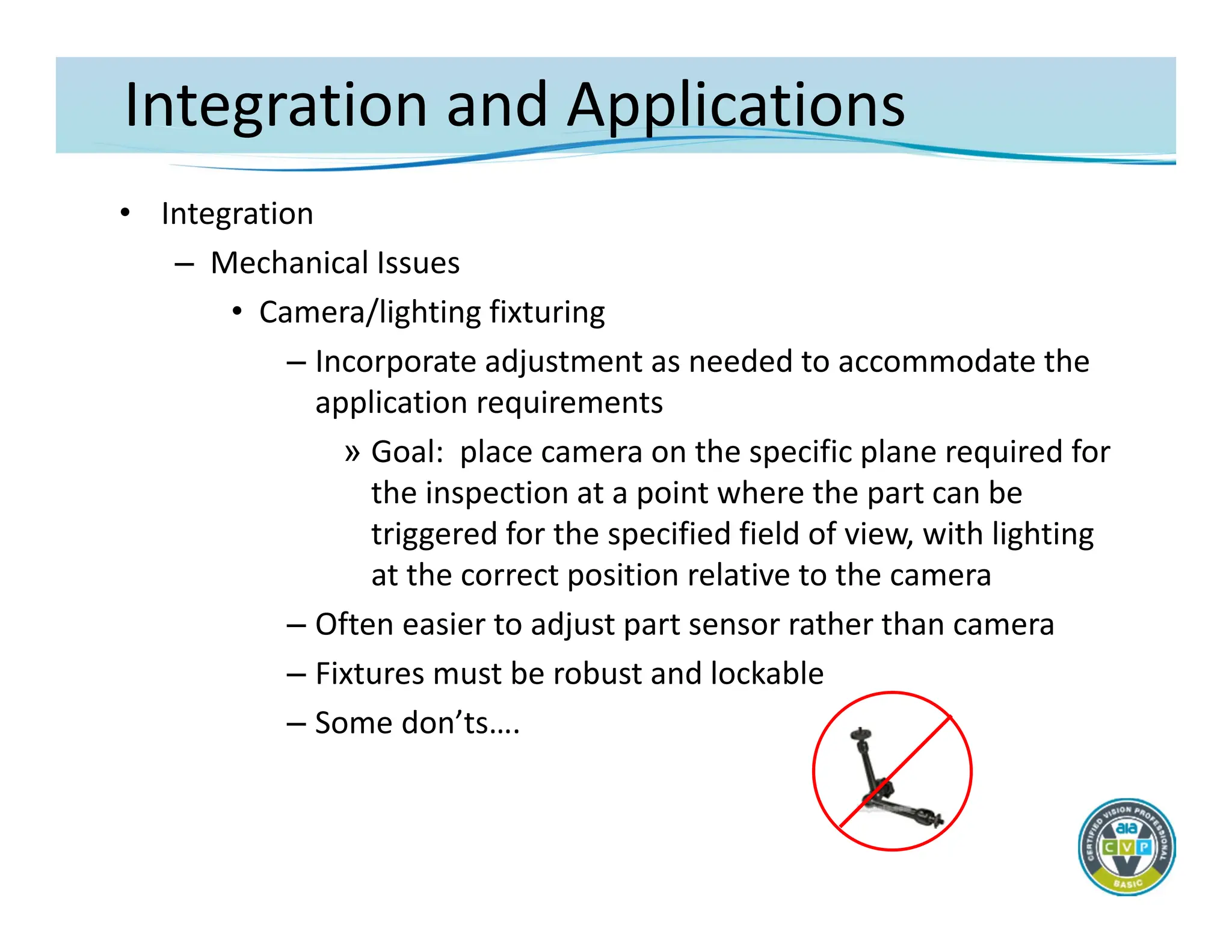
•Integration
– Mechanical Issues
• Camera/lighting fixturing
– Incorporate adjustment as needed to accommodate the
application requirements
» Goal: place camera on the specific plane required for
the inspection at a point where the part can be
triggered for the specified field of view, with lighting
at the correct position relative to the camera
– Often easier to adjust part sensor rather than camera
– Fixtures must be robust and lockable
– Some don’ts….
68.
Integration and Automation
•Integration
– Mechanical Issues
• Part presentation
– After lighting issues, part presentation is the most critical
and difficult part of most industrial applications
» Direct impact on the lighting and imaging
» Part must be presented in a generally repeatable
planar representation relative to the camera.
– If new automation, incorporate appropriate part handling
to enhance/benefit the inspection
– Where possible modify existing automation to constrain
part position
69.
Integration and Automation
•Integration
– Software and system configuration
• Where possible, prepare a preliminary imaging set‐up using the
final lighting and optics configuration and capture real production
images
• Use production images for inspection program development
– Configuring a basic machine vision inspection
• Image acquisition/processing
– Configure camera parameters
» Shutter, gain, offset, partial scanning, triggering
» Strobe light control
– Execute an inspection process upon image acquisition
– Tune the image if needed
» Filtering
» Morphology
70.
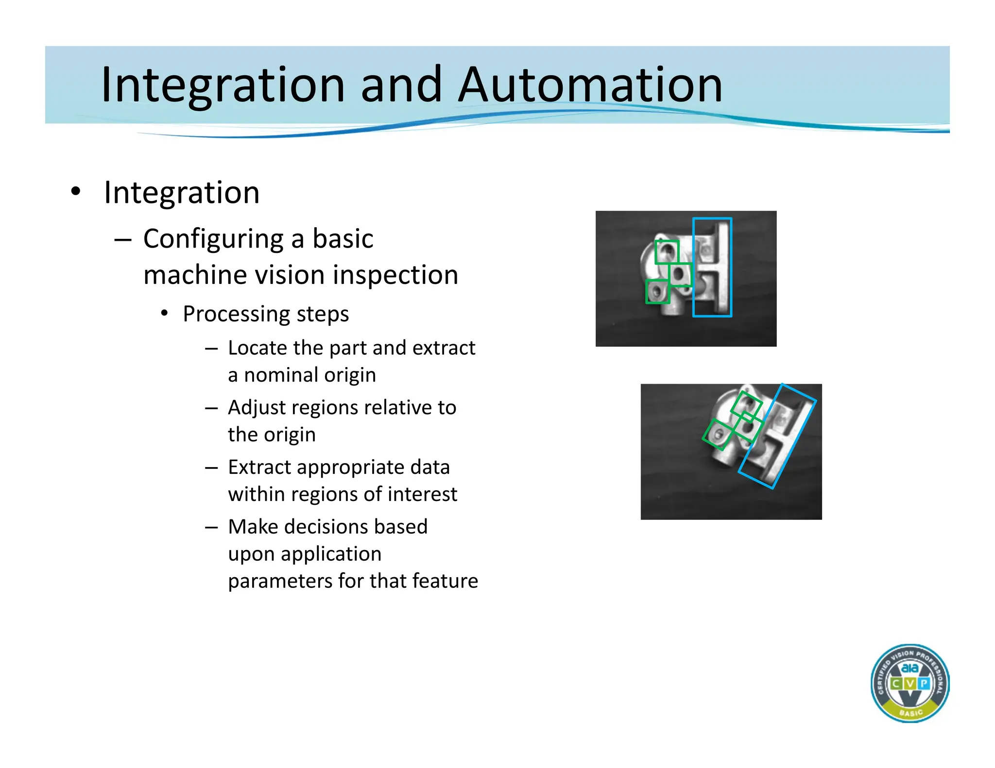
Integration and Automation
•Integration
– Configuring a basic
machine vision inspection
• Processing steps
– Locate the part and extract
a nominal origin
– Adjust regions relative to
the origin
– Extract appropriate data
within regions of interest
– Make decisions based
upon application
parameters for that feature
71.
Integration and Applications
•Results and Communications
– Installation/testing/startup
• Always implement control handshaking first
– Image acquisition, data exchange, and reject timing/co‐
ordination make up the largest part of on‐site systems
integration with an automation device
– Determine final camera/lighting mounting based upon
live production imaging
» Lock/pin all mounts once image is correct for all parts
• Test inspection algorithms on all samples with representative
failure modes
72.
Integration and Applications
•Results and Communications
– Discrete digital I/O may be required due to timing/signal latency
– Other communication protocols can be considered where
appropriate
– Incorporate proper handshaking when implementing signals with
external control devices
– Non‐critical data communications (not requiring deterministic
timing), such as part recipes, can be implemented with serial
(RS232/422), TCP/IP, “Ethernet/IP”, or specialty (Modbus,
DataHighway) interfaces.
– The system design must take into account inherent latencies in
these protocols
– About “network” communications
73.
Integration and Applications
•Basic Application Concepts
– Configure the desired inspection task utilizing appropriate tools
provided by the selected components
– Typical general‐purpose factory floor inspections
• Flaw detection
• Assembly Verification/Recognition
• Gauging/Metrology
• Location/Guidance
• OCR/OCV
– Note that virtually all applications will require the
implementation of multiple “tools” to successfully extract the
image data
74.
Integration and Applications
•Basic Application Concepts
– Defect/Flaw Detection
• A flaw is an object that is different from the normal immediate
background
• Imaging Issues
– Must have sufficient contrast and geometric features to be
differentiable from the background and other “good” objects
– Typically must be a minimum of 3x3 pixels in size and possibly
up to 50x50 pixels if contrast is low and defect classification is
required
– Reliable object classification may not be possible depending
upon geometric shape of the flaws
• Machine vision tools
– Binary pixel counting, morphology, edge extraction and
counting, image subtraction/golden template, blob analysis
75.
Integration and Applications
•Basic Application Concepts
– Assembly Verification/Object Recognition
• Feature presence/absence, identification, differentiation of similar
features
• Imaging Issues
– Must create adequate contrast between feature and
background
– Accommodate part and process variations – locate and correct
for part positional changes
– May require flexible lighting/imaging for varying features
– For feature presence/absence, feature should cover approx.
1% of the field of view (med. resolution camera), more for
identification or differentiation
• Machine vision tools
– Edge detection and measurement tools, blob analysis,
normalized correlation and pattern matching
76.
Integration and Applications
•Basic Application Concepts
– Gauging/Metrology
• Note: There are physical differences between gauging
features in an image produced by a camera, and the use of a
gage that contacts a part. These differences usually can not
be reconciled
• Gauging concepts
– Resolution, repeatability, accuracy
– Sub‐pixel measurement
– Measurement tolerances
– Resolution must be approximately 1/10 of required
accuracy in order to achieve gauge
reliability/repeatability
77.
Integration and Applications
•Basic Application Concepts
– Gauging/Metrology
• Imaging Issues
– Lighting to get a repeatable edge
» Backlighting, collimated light
– Telecentric lenses
– Calibration
» Correction for image perspective/plane
» Calibration error stack‐up
• Machine vision tools
– Edge detection and measurement, blob analysis
78.
Integration and Applications
•Basic Application Concepts
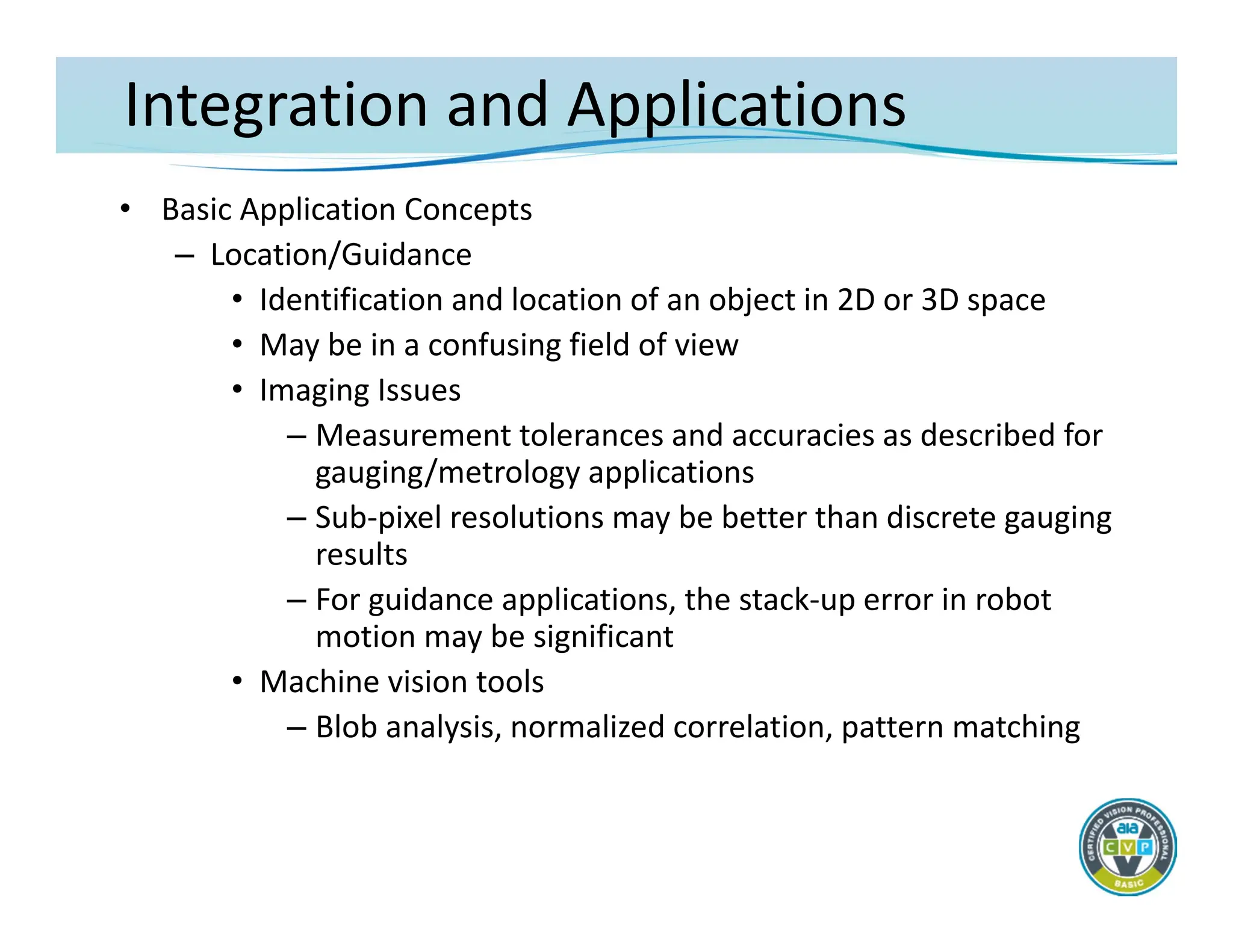
– Location/Guidance
• Identification and location of an object in 2D or 3D space
• May be in a confusing field of view
• Imaging Issues
– Measurement tolerances and accuracies as described for
gauging/metrology applications
– Sub‐pixel resolutions may be better than discrete gauging
results
– For guidance applications, the stack‐up error in robot
motion may be significant
• Machine vision tools
– Blob analysis, normalized correlation, pattern matching
79.
Integration and Applications
•Basic Application Concepts
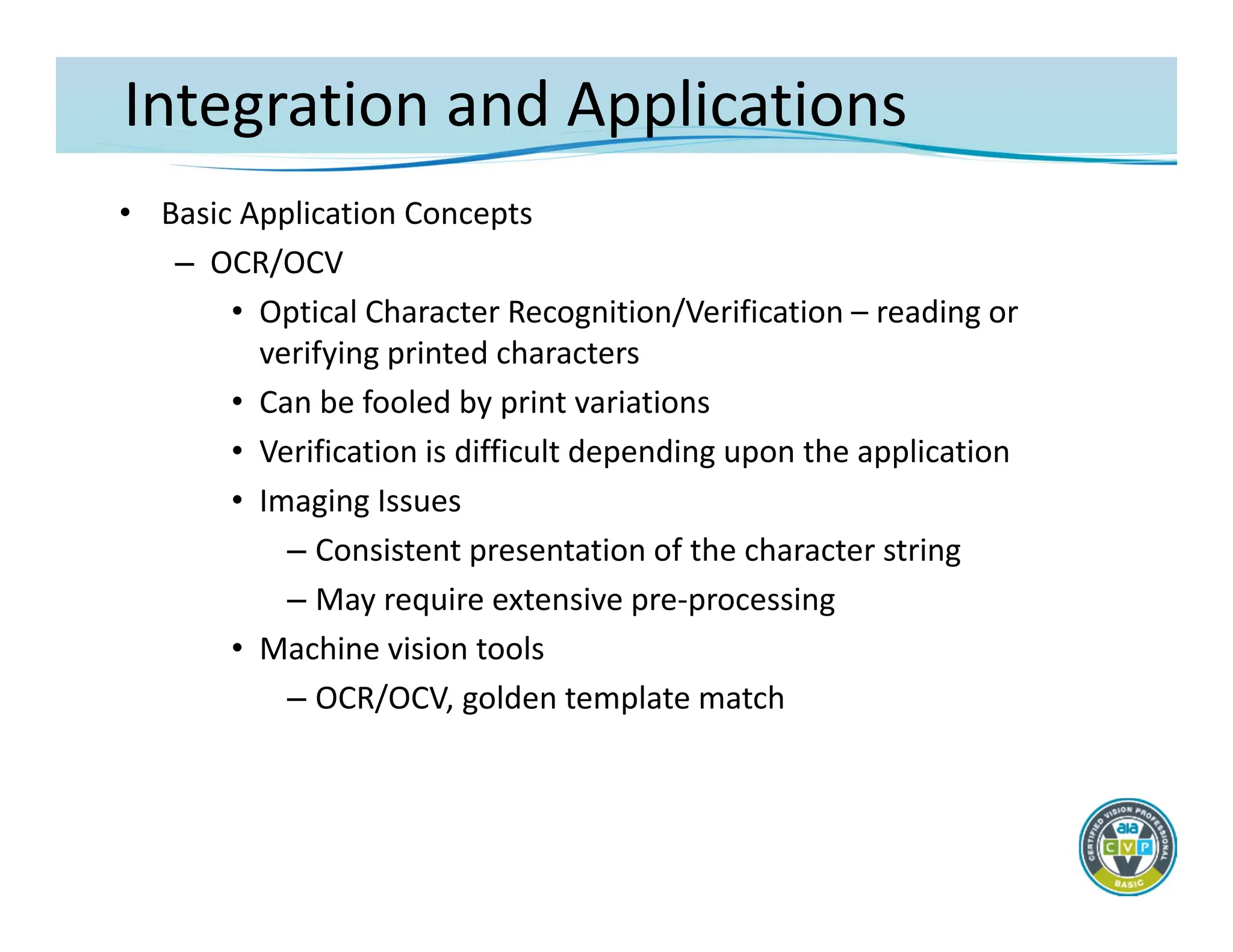
– OCR/OCV
• Optical Character Recognition/Verification – reading or
verifying printed characters
• Can be fooled by print variations
• Verification is difficult depending upon the application
• Imaging Issues
– Consistent presentation of the character string
– May require extensive pre‐processing
• Machine vision tools
– OCR/OCV, golden template match
80.
Integration and Applications
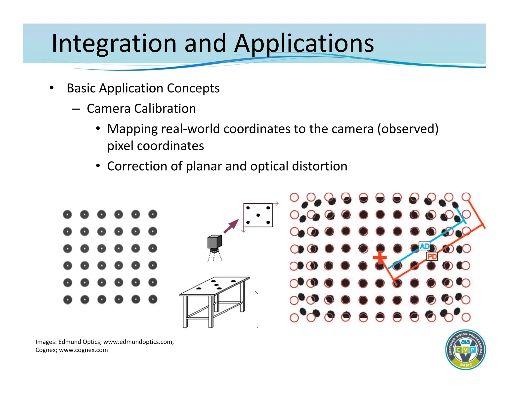
•Basic Application Concepts
– Camera Calibration
• Mapping real‐world coordinates to the camera (observed)
pixel coordinates
• Correction of planar and optical distortion
Images: Edmund Optics; www.edmundoptics.com,
Cognex; www.cognex.com


![Welcome to the New-Era in Automation]](https://cdn.slidesharecdn.com/ss_thumbnails/a73cde01-449f-4ab4-b012-7731e75ab889-160705040211-thumbnail.jpg?width=640&height=640&fit=bounds)


