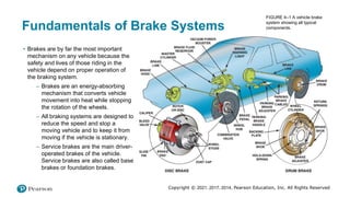
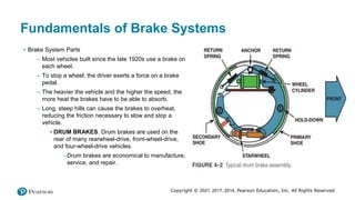
Copyright © 2021, 2017, 2014, Pearson Education, Inc. All Rights Reserved
Automotive Chassis Systems
Eighth Edition
Chapter 04
Braking System Components and
Performance Standards
Copyright © 2021, 2017, 2014, Pearson Education, Inc. All Rights Reserved
Objectives
• Describe the fundamentals of brake systems.
• Describe brake design requirements.
• List the six brake system categories.
• State the purpose of an antilock brake system.
• Discuss federal brake standards and legal aspects of brake repair.
Copyright © 2021, 2017, 2014, Pearson Education, Inc. All Rights Reserved
Fundamentals of Brake Systems
• Brakes are by far the most important
mechanism on any vehicle because the
safety and lives of those riding in the
vehicle depend on proper operation of
the braking system.
– Brakes are an energy-absorbing
mechanism that converts vehicle
movement into heat while stopping
the rotation of the wheels.
– All braking systems are designed to
reduce the speed and stop a
moving vehicle and to keep it from
moving if the vehicle is stationary.
– Service brakes are the main driver-
operated brakes of the vehicle.
Service brakes are also called base
brakes or foundation brakes.
FIGURE 4–1 A vehicle brake
system showing all typical
components.
Copyright © 2021, 2017, 2014, Pearson Education, Inc. All Rights Reserved
Fundamentals of Brake Systems
• Brake System Parts
– Most vehicles built since the late 1920s use a brake on
each wheel.
– To stop a wheel, the driver exerts a force on a brake
pedal.
– The heavier the vehicle and the higher the speed, the
more heat the brakes have to be able to absorb.
– Long, steep hills can cause the brakes to overheat,
reducing the friction necessary to slow and stop a
vehicle.
▪ DRUM BRAKES. Drum brakes are used on the
rear of many rearwheel-drive, front-wheel-drive,
and four-wheel-drive vehicles.
–Drum brakes are economical to manufacture,
service, and repair.
Copyright © 2021, 2017, 2014, Pearson Education, Inc. All Rights Reserved
Fundamentals of Brake Systems
• Brake System Parts
• Disc brakes are used on the front of most vehicles built since
the early 1970s, and on the rear wheels of many vehicles.
• A disc brake operates by squeezing brake pads on both
sides of a rotor or disc that is attached to the wheel.
•
Copyright © 2021, 2017, 2014, Pearson Education, Inc. All Rights Reserved
Fundamentals of Brake Systems
• Brake System Parts
– Due to the friction between the road surface and the tires, the vehicle stops.
– To summarize, the sequence of events necessary to stop a vehicle includes the following:
▪ The driver presses on the brake pedal.
▪ The brake pedal force is transferred hydraulically to a wheel cylinder or caliper at each wheel.
▪ Hydraulic pressure inside the wheel cylinder or caliper presses friction materials (brake shoes or pads)
against rotating brake drums or rotors.
▪ The friction slows and stops the drum or rotor. Since the drum or rotor is bolted to the wheel of the vehicle,
the wheel also stops.
▪ When the wheels of the vehicle slow and stop, the tires must have friction (traction) with the road surface to
stop the vehicle.
Copyright © 2021, 2017, 2014, Pearson Education, Inc. All Rights Reserved
Brake Design Requirements
• All braking forces must provide for the following:
– Equal forces must be applied to both the left and right sides of the vehicle to assure straight stops.
– Hydraulic systems must be properly engineered and serviced to provide for changes as vehicle weight shifts
forward during braking.
– The hydraulic system must use a fluid that does not evaporate or freeze.
– The friction material (brake lining or brake pads) must be designed to provide adequate friction between the
stationary axles and the rotating drum or rotor.
– The design of the braking system should secure the brake lining solidly to prevent the movement of the friction
material during braking.
– Most braking systems incorporate a power assist unit that reduces the driver’s effort, but does not reduce
stopping distance.
Copyright © 2021, 2017, 2014, Pearson Education, Inc. All Rights Reserved
Brake System Categories
• Brake system components can be classified and placed into
six subsystem categories, depending on their function.
– Apply system. The driver starts the operation of the
braking system by pressing on the brake pedal or
applying the parking brake.
– Boost system. The boost (power brake) system is
used on most vehicles to reduce the force that the
driver must exert on the brake pedal.
– Hydraulic system. The brake pedal force is transferred
to the hydraulic system, where the force is directed
through pipes and hoses to the wheel brakes.
– Wheel brakes. Hydraulic pressure from the hydraulic
system moves a piston, in either a disc or drum brake
system, which uses friction to press material against a
rotating drum or rotor.
– Brake balance control system. Mechanical, electrical,
and hydraulic components are used to ensure that
brakes are applied quickly and with balanced pressure
for safe operation.
FIGURE 4–4 Typical brake system components.
Copyright © 2021, 2017, 2014, Pearson Education, Inc. All Rights Reserved
Brake System Categories
– Brake System Categories
▪ Wheel brakes. Hydraulic pressure from the
hydraulic system moves a piston, in either a disc or
drum brake system, which uses friction to press
material against a rotating drum or rotor.
▪ Brake balance control system. Mechanical,
electrical, and hydraulic components are used to
ensure that brakes are applied quickly and with
balanced pressure for safe operation.
▪ Brake warning lights. There are two brake system–
related warning lights:
–The red brake warning lamp (RBWL) lights
whenever a hydraulic system failure occurs or
low brake fluid level has been detected.
–The amber ABS warning lamp or dim red
brake light indicates an ABS self-test and/or a
possible problem in the ABS.
Copyright © 2021, 2017, 2014, Pearson Education, Inc. All Rights Reserved
Antilock Brake System Overview
• ABS
– The purpose of an antilock brake system (ABS) is to
prevent the wheels from locking during braking,
especially on low-friction surfaces, such as wet, icy, or
snowy roads.
– The ABS computer can reapply the pressure from the
master cylinder to the wheel a fraction of a second later.
– If a wheel starts to lock up, the purpose of the ABS is to
pulse the brakes on and off to maintain directional
stability with maximum braking force.
– Another symptom of normal ABS unit operation is the
activation of the hydraulic pressure pump used by many
ABS units.
FIGURE 4–8 Typical components of an antilock brake system
(ABS) used on a rear-wheel-drive vehicle.
Copyright © 2021, 2017, 2014, Pearson Education, Inc. All Rights Reserved
Federal Brake Standards
– The statutes pertaining to automotive brake systems are part of the Federal Motor Vehicle Safety Standards
(FMVSS) established by the U.S. Department of Transportation (DOT). Several standards apply to specific
components within the brake system.
– FMVSS 135 was first mandated on September 1, 2000, for passenger vehicles, and September 1, 2002, for
multipurpose vehicles, trucks, and buses with a gross vehicle weight rating (GVWR) of 7,716 pounds (3,500
kg).
▪ Its purpose is to “ensure safe braking performance under normal and emergency conditions.”
– FMVSS 135 deals with brake system safety by establishing specific brake performance requirements.
– Only four parts of the brake system are specifically regulated:
▪ Fluid reservoir and labeling
▪ Dashboard warning lights
▪ A method of automatic adjustment
▪ A mechanically engaging, friction-type parking brake system
– The FMVSS 135 tests are used by manufacturers to certify the braking performance of all new vehicles
available for public purchase.
Copyright © 2021, 2017, 2014, Pearson Education, Inc. All Rights Reserved
FMVSS 135 Brake Test
• The overall FMVSS 135 brake test procedure consists of up to 24 steps, depending on the vehicle’s configuration
and braking system.
– The actual performance tests are made with the vehicle loaded to both the manufacturer’s specified gross
vehicle weight rating (GVWR) and the lightly loaded vehicle weight (LLVW), with certain applied brake forces.
▪ Burnish Procedure. The brakes are burnished by making 200 stops from 50 mph (80 km/h) at a fixed rate
of deceleration with a controlled cool-down period after each stop.
▪ Adhesion Utilization (torque wheel method). For vehicles not equipped with ABS, this test is to
determine if the brake system makes adequate use of the road surface in stopping the vehicle.
▪ Cold Effectiveness. This test is performed to determine if the vehicle has sufficient stopping power when
the brake lining materials are not preheated by previous stops.
▪ High-Speed Effectiveness. This test is performed to determine if the brake system provides adequate
stopping power for all loading conditions.
▪ Stops with the Engine Off. This test is for vehicles equipped with brake power assist units.
▪ Antilock Functional Failure. This test ensures that service brakes function correctly in the event of an
antilock functional failure, and the brake system warning indicator is activated when an ABS electrical
function failure occurs.
Copyright © 2021, 2017, 2014, Pearson Education, Inc. All Rights Reserved
FMVSS 135 Brake Test
• FMVSS 135 Test
▪ Variable Brake Proportioning System. This test is performed on vehicles equipped with either a
mechanical or an electrical variable proportioning system.
▪ Hydraulic Circuit Failure. This test is performed to ensure that the driver is alerted via the brake warning
system indicator that a failure has occurred, and that the vehicle can still be stopped in an acceptable
distance.
▪ Brake Power Assist Unit Inoperative. This test makes sure the service brake can stop the vehicle in an
acceptable distance with the brake power assist unit in an inoperative state.
▪ Parking Brake. The parking brake alone holds the vehicle stationary in either the forward or reverse
direction on a 20% grade for a period of at least five minutes.
▪ Brake Heat Test. This procedure heats the brake system by making a series of 15 stops from a high
speed.
▪ Hot Performance. After the brake system has been heated by a series of heating snubs, the hot
performance test is immediately performed. The vehicle is loaded to GVWR and two stops are made.
– Although these tests may seem extreme, they are only a minimum standard of performance.
– Any brake repair work should also leave the brake system capable of meeting FMVSS 135.
Copyright © 2021, 2017, 2014, Pearson Education, Inc. All Rights Reserved
Brake Repair and the Law
• Once a vehicle leaves the factory, the responsibility for maintaining the designed-in level of braking performance falls
on the owner of the vehicle.
– Owners look to trained automotive technicians to service their brake systems.
– Regardless of whether there are specific laws governing brake repair, a technician is always liable for damage
or injuries resulting from repairs performed in an unprofessional or unworkmanlike manner.
– Considering the lives and property that depend on good brakes, there is only one acceptable goal when making
brake system repairs: to restore the system and its component parts so they perform to original specifications.
In other words, the purpose of any repair is to restore like-new performance.
Copyright © 2021, 2017, 2014, Pearson Education, Inc. All Rights Reserved
Summary
• Brakes are an energy-absorbing mechanism that convert vehicle movement into heat while stopping the rotation of
the wheels.
• Brake system components can be classified and placed into six subsystem categories, depending on their function
including:
– Apply system. The driver starts the operation of the braking system by pressing on the brake pedal or applying
the parking brake needed to activate a braking force.
– Boost system. The boost (power brake) system is used on most vehicles to reduce the force that the driver
must exert on the brake pedal.
– Hydraulic system. The brake pedal force is transferred to the hydraulic system, where the force is directed
through pipes and hoses to the wheel brakes.
– Wheel brakes. Hydraulic pressure from the hydraulic system moves a piston, in either a disc or drum brake
system, which uses friction to press material against a rotating drum or rotor. The resulting friction slows the
rotation of the wheels.
– Brake balance control system. Mechanical, electrical, and hydraulic components are used to ensure that
brakes are applied quickly and with balanced pressure for safe operation.
– Brake warning lights.
Copyright © 2021, 2017, 2014, Pearson Education, Inc. All Rights Reserved
Summary Cont….
• The purpose of an antilock brake system (ABS) is to prevent the wheels from locking during braking, especially on
low-friction surfaces, such as wet, icy, or snowy roads.
• The statutes pertaining to automotive brake systems are part of the Federal Motor Vehicle Safety Standards
(FMVSS) established by the U.S. Department of Transportation (DOT).
• Once a vehicle leaves the factory, the responsibility for maintaining the designed-in level of braking performance falls
on the owner of the vehicle.

4 Braking System Components and Performance Standards.pptx

  • 1.
    Copyright © 2021,2017, 2014, Pearson Education, Inc. All Rights Reserved Automotive Chassis Systems Eighth Edition Chapter 04 Braking System Components and Performance Standards
  • 2.
    Copyright © 2021,2017, 2014, Pearson Education, Inc. All Rights Reserved Objectives • Describe the fundamentals of brake systems. • Describe brake design requirements. • List the six brake system categories. • State the purpose of an antilock brake system. • Discuss federal brake standards and legal aspects of brake repair.
  • 3.
    Copyright © 2021,2017, 2014, Pearson Education, Inc. All Rights Reserved Fundamentals of Brake Systems • Brakes are by far the most important mechanism on any vehicle because the safety and lives of those riding in the vehicle depend on proper operation of the braking system. – Brakes are an energy-absorbing mechanism that converts vehicle movement into heat while stopping the rotation of the wheels. – All braking systems are designed to reduce the speed and stop a moving vehicle and to keep it from moving if the vehicle is stationary. – Service brakes are the main driver- operated brakes of the vehicle. Service brakes are also called base brakes or foundation brakes. FIGURE 4–1 A vehicle brake system showing all typical components.
  • 4.
    Copyright © 2021,2017, 2014, Pearson Education, Inc. All Rights Reserved Fundamentals of Brake Systems • Brake System Parts – Most vehicles built since the late 1920s use a brake on each wheel. – To stop a wheel, the driver exerts a force on a brake pedal. – The heavier the vehicle and the higher the speed, the more heat the brakes have to be able to absorb. – Long, steep hills can cause the brakes to overheat, reducing the friction necessary to slow and stop a vehicle. ▪ DRUM BRAKES. Drum brakes are used on the rear of many rearwheel-drive, front-wheel-drive, and four-wheel-drive vehicles. –Drum brakes are economical to manufacture, service, and repair.
  • 5.
    Copyright © 2021,2017, 2014, Pearson Education, Inc. All Rights Reserved Fundamentals of Brake Systems • Brake System Parts • Disc brakes are used on the front of most vehicles built since the early 1970s, and on the rear wheels of many vehicles. • A disc brake operates by squeezing brake pads on both sides of a rotor or disc that is attached to the wheel. •
  • 6.
    Copyright © 2021,2017, 2014, Pearson Education, Inc. All Rights Reserved Fundamentals of Brake Systems • Brake System Parts – Due to the friction between the road surface and the tires, the vehicle stops. – To summarize, the sequence of events necessary to stop a vehicle includes the following: ▪ The driver presses on the brake pedal. ▪ The brake pedal force is transferred hydraulically to a wheel cylinder or caliper at each wheel. ▪ Hydraulic pressure inside the wheel cylinder or caliper presses friction materials (brake shoes or pads) against rotating brake drums or rotors. ▪ The friction slows and stops the drum or rotor. Since the drum or rotor is bolted to the wheel of the vehicle, the wheel also stops. ▪ When the wheels of the vehicle slow and stop, the tires must have friction (traction) with the road surface to stop the vehicle.
  • 7.
    Copyright © 2021,2017, 2014, Pearson Education, Inc. All Rights Reserved Brake Design Requirements • All braking forces must provide for the following: – Equal forces must be applied to both the left and right sides of the vehicle to assure straight stops. – Hydraulic systems must be properly engineered and serviced to provide for changes as vehicle weight shifts forward during braking. – The hydraulic system must use a fluid that does not evaporate or freeze. – The friction material (brake lining or brake pads) must be designed to provide adequate friction between the stationary axles and the rotating drum or rotor. – The design of the braking system should secure the brake lining solidly to prevent the movement of the friction material during braking. – Most braking systems incorporate a power assist unit that reduces the driver’s effort, but does not reduce stopping distance.
  • 8.
    Copyright © 2021,2017, 2014, Pearson Education, Inc. All Rights Reserved Brake System Categories • Brake system components can be classified and placed into six subsystem categories, depending on their function. – Apply system. The driver starts the operation of the braking system by pressing on the brake pedal or applying the parking brake. – Boost system. The boost (power brake) system is used on most vehicles to reduce the force that the driver must exert on the brake pedal. – Hydraulic system. The brake pedal force is transferred to the hydraulic system, where the force is directed through pipes and hoses to the wheel brakes. – Wheel brakes. Hydraulic pressure from the hydraulic system moves a piston, in either a disc or drum brake system, which uses friction to press material against a rotating drum or rotor. – Brake balance control system. Mechanical, electrical, and hydraulic components are used to ensure that brakes are applied quickly and with balanced pressure for safe operation. FIGURE 4–4 Typical brake system components.
  • 9.
    Copyright © 2021,2017, 2014, Pearson Education, Inc. All Rights Reserved Brake System Categories – Brake System Categories ▪ Wheel brakes. Hydraulic pressure from the hydraulic system moves a piston, in either a disc or drum brake system, which uses friction to press material against a rotating drum or rotor. ▪ Brake balance control system. Mechanical, electrical, and hydraulic components are used to ensure that brakes are applied quickly and with balanced pressure for safe operation. ▪ Brake warning lights. There are two brake system– related warning lights: –The red brake warning lamp (RBWL) lights whenever a hydraulic system failure occurs or low brake fluid level has been detected. –The amber ABS warning lamp or dim red brake light indicates an ABS self-test and/or a possible problem in the ABS.
  • 10.
    Copyright © 2021,2017, 2014, Pearson Education, Inc. All Rights Reserved Antilock Brake System Overview • ABS – The purpose of an antilock brake system (ABS) is to prevent the wheels from locking during braking, especially on low-friction surfaces, such as wet, icy, or snowy roads. – The ABS computer can reapply the pressure from the master cylinder to the wheel a fraction of a second later. – If a wheel starts to lock up, the purpose of the ABS is to pulse the brakes on and off to maintain directional stability with maximum braking force. – Another symptom of normal ABS unit operation is the activation of the hydraulic pressure pump used by many ABS units. FIGURE 4–8 Typical components of an antilock brake system (ABS) used on a rear-wheel-drive vehicle.
  • 11.
    Copyright © 2021,2017, 2014, Pearson Education, Inc. All Rights Reserved Federal Brake Standards – The statutes pertaining to automotive brake systems are part of the Federal Motor Vehicle Safety Standards (FMVSS) established by the U.S. Department of Transportation (DOT). Several standards apply to specific components within the brake system. – FMVSS 135 was first mandated on September 1, 2000, for passenger vehicles, and September 1, 2002, for multipurpose vehicles, trucks, and buses with a gross vehicle weight rating (GVWR) of 7,716 pounds (3,500 kg). ▪ Its purpose is to “ensure safe braking performance under normal and emergency conditions.” – FMVSS 135 deals with brake system safety by establishing specific brake performance requirements. – Only four parts of the brake system are specifically regulated: ▪ Fluid reservoir and labeling ▪ Dashboard warning lights ▪ A method of automatic adjustment ▪ A mechanically engaging, friction-type parking brake system – The FMVSS 135 tests are used by manufacturers to certify the braking performance of all new vehicles available for public purchase.
  • 12.
    Copyright © 2021,2017, 2014, Pearson Education, Inc. All Rights Reserved FMVSS 135 Brake Test • The overall FMVSS 135 brake test procedure consists of up to 24 steps, depending on the vehicle’s configuration and braking system. – The actual performance tests are made with the vehicle loaded to both the manufacturer’s specified gross vehicle weight rating (GVWR) and the lightly loaded vehicle weight (LLVW), with certain applied brake forces. ▪ Burnish Procedure. The brakes are burnished by making 200 stops from 50 mph (80 km/h) at a fixed rate of deceleration with a controlled cool-down period after each stop. ▪ Adhesion Utilization (torque wheel method). For vehicles not equipped with ABS, this test is to determine if the brake system makes adequate use of the road surface in stopping the vehicle. ▪ Cold Effectiveness. This test is performed to determine if the vehicle has sufficient stopping power when the brake lining materials are not preheated by previous stops. ▪ High-Speed Effectiveness. This test is performed to determine if the brake system provides adequate stopping power for all loading conditions. ▪ Stops with the Engine Off. This test is for vehicles equipped with brake power assist units. ▪ Antilock Functional Failure. This test ensures that service brakes function correctly in the event of an antilock functional failure, and the brake system warning indicator is activated when an ABS electrical function failure occurs.
  • 13.
    Copyright © 2021,2017, 2014, Pearson Education, Inc. All Rights Reserved FMVSS 135 Brake Test • FMVSS 135 Test ▪ Variable Brake Proportioning System. This test is performed on vehicles equipped with either a mechanical or an electrical variable proportioning system. ▪ Hydraulic Circuit Failure. This test is performed to ensure that the driver is alerted via the brake warning system indicator that a failure has occurred, and that the vehicle can still be stopped in an acceptable distance. ▪ Brake Power Assist Unit Inoperative. This test makes sure the service brake can stop the vehicle in an acceptable distance with the brake power assist unit in an inoperative state. ▪ Parking Brake. The parking brake alone holds the vehicle stationary in either the forward or reverse direction on a 20% grade for a period of at least five minutes. ▪ Brake Heat Test. This procedure heats the brake system by making a series of 15 stops from a high speed. ▪ Hot Performance. After the brake system has been heated by a series of heating snubs, the hot performance test is immediately performed. The vehicle is loaded to GVWR and two stops are made. – Although these tests may seem extreme, they are only a minimum standard of performance. – Any brake repair work should also leave the brake system capable of meeting FMVSS 135.
  • 14.
    Copyright © 2021,2017, 2014, Pearson Education, Inc. All Rights Reserved Brake Repair and the Law • Once a vehicle leaves the factory, the responsibility for maintaining the designed-in level of braking performance falls on the owner of the vehicle. – Owners look to trained automotive technicians to service their brake systems. – Regardless of whether there are specific laws governing brake repair, a technician is always liable for damage or injuries resulting from repairs performed in an unprofessional or unworkmanlike manner. – Considering the lives and property that depend on good brakes, there is only one acceptable goal when making brake system repairs: to restore the system and its component parts so they perform to original specifications. In other words, the purpose of any repair is to restore like-new performance.
  • 15.
    Copyright © 2021,2017, 2014, Pearson Education, Inc. All Rights Reserved Summary • Brakes are an energy-absorbing mechanism that convert vehicle movement into heat while stopping the rotation of the wheels. • Brake system components can be classified and placed into six subsystem categories, depending on their function including: – Apply system. The driver starts the operation of the braking system by pressing on the brake pedal or applying the parking brake needed to activate a braking force. – Boost system. The boost (power brake) system is used on most vehicles to reduce the force that the driver must exert on the brake pedal. – Hydraulic system. The brake pedal force is transferred to the hydraulic system, where the force is directed through pipes and hoses to the wheel brakes. – Wheel brakes. Hydraulic pressure from the hydraulic system moves a piston, in either a disc or drum brake system, which uses friction to press material against a rotating drum or rotor. The resulting friction slows the rotation of the wheels. – Brake balance control system. Mechanical, electrical, and hydraulic components are used to ensure that brakes are applied quickly and with balanced pressure for safe operation. – Brake warning lights.
  • 16.
    Copyright © 2021,2017, 2014, Pearson Education, Inc. All Rights Reserved Summary Cont…. • The purpose of an antilock brake system (ABS) is to prevent the wheels from locking during braking, especially on low-friction surfaces, such as wet, icy, or snowy roads. • The statutes pertaining to automotive brake systems are part of the Federal Motor Vehicle Safety Standards (FMVSS) established by the U.S. Department of Transportation (DOT). • Once a vehicle leaves the factory, the responsibility for maintaining the designed-in level of braking performance falls on the owner of the vehicle.