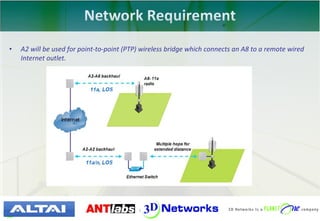
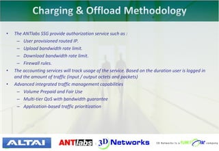
discover          design                        deploy             manage

                      Yudhistira Sutjipto
           Presales Manager of 3DNetwork Indonesia


                    11 |© 2010 3D Networks. All rights reserved.
                     | © 2010 3D Networks. All rights reserved.
Carrier grade wireless LAN for 3G offloading
•   Network Component (radio access, radio backhaul and wireless management system) by Altai
     – Altai A8 Super WiFi Base Station
     – Altai A8-Ei Super WiFi Base Station
     – Altai A2 WiFi Access Point/Bridge
     – Altai C1 Super WiFi CPE
     – Altai Wireless Management System (AWMS)
•   Charging and offload system component (authentication; authorization and accounting
    function) by ANTLabs.
     – ANTlabs Service Selection Gateway (SSG)
     – ANTlabs Tru’Auth Radius System (Tru’Auth)
•   Installation, integration & maintenance by 3D Networks


                                   2 | © 2010 3D Networks. All rights reserved.
Network Component
•   Altai A8 Super WiFi Base Station
     – Extended coverage in a Non-Line-of-Sight (NLOS) environment
     – Dual-diversity advanced Smart Antenna Technology to provide flexible 90 to
       360-degree coverage
     – Multi-radio platform to maximize both uplink/downlink performance and
       access redundancy
     – Backhaul resilience and 1+1 protective switching
     – Adaptive interference control to mitigate the surrounding interference effects
     – Supports real-time applications such as VoIP, video-streaming and interactive
       gaming with minimal latency
     – Standard 802.11b/g access (802.11n Q112)and 802.11a backhaul
     – Fast Ethernet or integrated 802.11a wireless backhaul
     – Flexible antenna deployment for various site conditions
     – Remote configuration through the Altai Wireless Management System
       (AWMS)


                                        3 | © 2010 3D Networks. All rights reserved.
Network Component
•   Altai A8-Ei Super WiFi Base Station
     – Same base station unit as of the Altai A8 but with integrated multi-beam antenna array all
         in one chassis
     – A8-Ei multi-beam antenna array provide up to 5 times the range and 20 times the per site
         coverage as traditional access point.


                                    4 | © 2010 3D Networks. All rights reserved.
Network Component
•   Altai A2/A2e WiFi Access Point/Bridge
     – Multi-operating modes allowed: AP, bridge, repeater mode or CPE
     – 2 x 2 MIMO for both 2.4GHz (802.11bgn) and 5 GHz (802.11an)
         radios
     – IP-67 rated carrier grade 802.11b/g/n AP for both outdoor and
         indoor applications
     – Increase system capacity under the coverage area of A8 Super WiFi
         Base Station
     – Fast Ethernet or 2 x 2 802.11an wireless backhaul
     – PTP and PTMP bridging with built-in dual polarized panel antenna
     – Light weight with built-in lightning protection
     – Easy installation & web-based management


                                   5 | © 2010 3D Networks. All rights reserved.
Network Component
•   Altai C1 Super WiFi CPE
     – Features built-in for carriers including per client/VAP bandwidth
         control, remote web-based management and client performance
         statistics
     – ±45° cross-polarized patch antennas are optimized to match with
         the Altai A8 /A8-Ei antennas. (provides 3 dB more gain as
         compared to other V-H polarized CPEs)
     – High performance antenna with 20 dB front-to-back ratio (5 dB
         better than others in directional transmission)
     – IP55 standard for direct outdoor installation
     – 8-level LED for easy alignment in the strongest signal direction
     – Increase signal strength for both NLOS and LOS coverage areas


                                    6 | © 2010 3D Networks. All rights reserved.
Network Component
•   Altai Wireless Management System (AWMS)
     – Centralized management of network equipment
     – Automatic BTS/AP detection and provisioning
     – Template-based multiple BTS/AP configuration
     – User-friendly graphical interface with network map
     – Real-time network monitoring and proactive fault handling
     – Inventory and connection status
     – Multi-layer security management
     – Performance monitoring
     – WiFi CPE management
     – WiFi client association reporting
     – Remote firmware upgrade


                                   7 | © 2010 3D Networks. All rights reserved.
Charging and offload system component
•   ANTlabs Service Selection Gateway (SSG)
     – Support multiple authentication mechanisms to fit different business requirements and
        deployment scenarios (802.1x Authentication)
     – Authorization, providing a suitable level of “service” for the given user (after
        authentication). Offer differentiate service plans to tap on the ability of different users to
        pay for services such as :
          •   User provisioned routed IP.
          •   Upload bandwidth rate limit.
          •   Download bandwidth rate limit.
          •   Firewall rules.
     – Accounting - based on logged in duration and the amount of traffic (input / output octets
       and packets).


                                           8 | © 2010 3D Networks. All rights reserved.
Charging and offload system component
•   ANTlabs Service Selection Gateway (SSG)
     – Traffic/Service Management - allows the service provider to offer dynamic service plans
        that can be changed on the fly to meet the specific needs of the user
          • Volume Prepaid and Fair Use
          • Multi-tier QoS with bandwidth guarantee
          • Application-based traffic prioritization
     – Built-in Anti-DoS and anti-SPAM features to defend itself against intentional and
       unintentional malicious users.
     – Provides scalable capacity, starting from 500 concurrent devices up to a maximum of
       10,000 concurrent devices.


                                          9 | © 2010 3D Networks. All rights reserved.
Charging and offload system component
•   ANTlabs Tru’Auth Radius System (Tru’Auth)
     – Template-based profile/ account type definitions, such as
          •   Single use time-based and volume-based prepaid accounts.
          •   Recurring time-based and volume-based prepaid accounts.
          •   Day and time restricted access accounts.
          •   Post-paid accounts
     – Service Management Features :
          • EAP-SIM SIGTRANS interface - interface directly with the HLR for EAP-SIM authentication.
          • 802.1x Support
     – Logs & Reports
          •   Subscriber Dashboard.
          •   Accounting Log.
          •   Online Users Log.
          •   Failed User Login Log.
          •   Usage Summary
     – Extendable via Application Programming Interface (API)

                                           10 | © 2010 3D Networks. All rights reserved.
•   Jakarta : dense-urban area – commercial area. The building heights range from 5 floors to over
    30 floors. Buildings are made of concrete materials with large building blocks.


                                    11 | © 2010 3D Networks. All rights reserved.
Core Network


                                                                 Application Server
                                 Service Controller


Backhaul                              A2 (bridge)
                                                                                              A8 when placed inside provides
                                                                                              coverage to most indoor areas
Access
                                                             A2 (repeater)
   A2 (pico)
                               Pool

                                          Hotel rooms                C1 (CPE-AP)
                          Garden                                                                                 IP-WAN


     A8 provides direct coverage to
     guess rooms from both sides
                                                        A8              Lobby areas                  Shopping mall
                                                                              C1 extends signal to
         2.4 GHz                                                              indoor
         5 GHz                              12 | © 2010 3D Networks. All rights reserved.
A2e WiFi
Bridge
                                    2 to 3 A2e Access Points for
                                     each floor zone coverage
                                     with stronger penetration
                                    Input end of the switch
     A2e - High Floor
                                     connect to a A2e WiFi
                                     Bridge which can establish
      A2e - Middle Floor
                                     5 GHz radio bridge as
                                     backhaul link
     A2e - Low Floor


           13 | © 2010 3D Networks. All rights reserved.
•   A8 will be used for primary outdoor coverage. (horizontal beamwidth : 70-degrees and vertical
    beamwidth : 12-degrees)
     – NLOS coverage radius of 350 to 500 m across the sub-urban areas where the buildings are
        relatively low-raised
     – Dense-urban areas with high-raised buildings, the coverage is highly dependable on the
        building and street structure, a 250 m NLOS coverage radius along a street.
     – Outdoor open areas such as park, A8 can provide a near LOS radius of up to 1 km or more

                    Environment        Coverage Radius (r)       Coverage Area (2r2)     No. of A8/ km2

                Open area (near LOS)         1000 m                       2 km2               0.5

                Rural (NLOS)                  500 m                      0.5 km2               2

                Sub-urban (NLOS)              350 m                     0.25 km2               4

                Dense-urban (NLOS)            250 m                    0.125 km2               8


                                         14 | © 2010 3D Networks. All rights reserved.
•   A8 base station has both a wired Ethernet port and a 5 GHz wireless backhaul for connection to
    the backend network.


                                    15 | © 2010 3D Networks. All rights reserved.
•   A8-Ei can be used for outdoor coverage instead of A8 in the following circumstances:
     – The maximum target coverage radius exceeds that of the A8 or the coverage areas are in long sector
       shape, e.g. along a street, airbase coverage, long range wireless DSL.
     – Coverage to a remote discrete area separated by highway or sea at distant away exceed that of A8, e.g.
       island, offshore oil refining telemetry, coverage for tourist boats at middle of a lake
     – Higher link budget is desired where higher received signal strength is necessary, e.g. indoor penetration,
       support VoIP
     – Larger site coverage area at the same user capacity than that of A8 is desired, e.g. rural residential area
       with large footprint and low population density


              Environment                     Coverage Radius (A8-Ei)                    Coverage Radius (A8)

              Open area (near LOS)                      1700 m                                 1000 m
              Rural (NLOS)                               800 m                                  500 m
              Sub-urban (NLOS)                           500 m                                  350 m
              Dense-urban (NLOS)                         350 m                                  250 m


                                         16 | © 2010 3D Networks. All rights reserved.
•   With 250m base station separation, 70% of indoor coverage can be achieved. Outdoor street
    level WiFi repeaters are installed in blind spot in coverage area to enhance the indoor coverage
    to 95%.

                    Base Station       Outdoor               Outdoor              Indoor coverage      Indoor
        Region       Separation    coverage without        coverage with              without       coverage with
                      Distance         repeater              repeater                repeater         repeater
     Dense Urban       250m              85%                   97%                     70%              95%
      Sub-urban        500m              85%                   97%                     60%              95%
        Rural           1km              85%                   97%                     50%              95%


                                       17 | © 2010 3D Networks. All rights reserved.
•   In Wireless DSL model, Altai Super WiFi BTS is installed to provide reasonable outdoor coverage
    to normal WiFi device. Then, Altai C1 CPE is installed in end-user home or office to extend the
    indoor coverage

                            Base Station
                             Separation        Outdoor coverage           Indoor coverage   Indoor coverage
             Region           Distance          without C1 CPE             without C1 CPE     with C1 CPE
          Dense Urban          500m                     75%                       40%            90%
            Sub-urban          1km                      75%                       40%            90%
              Rural            2km                      75%                       40%            90%


                                      18 | © 2010 3D Networks. All rights reserved.
•   A2 will be used for point-to-point (PTP) wireless bridge which connects an A8 to a remote wired
    Internet outlet.


                                     19 | © 2010 3D Networks. All rights reserved.
•   Multiple A2-A8 PTP pairs can be grouped together to form an A8 cluster. In the figure below,
    three dedicated 802.11a paths are formed with total throughput of 3 x 20 Mbps available.


                                    20 | © 2010 3D Networks. All rights reserved.
•   Distances between various combination of A2 and A8, using different panel or omni antennas
    are :
                       Far End     A2 with built-in              A8 with external   A8 with external 9
       Near End                     16 dBi panel                   18 dBi panel         dBi omni
       A2 built-in 16 dBi panel         12 km                           13 km            5.0 km
       A8 external 18 dBi panel         13 km                           12 km            5.0 km
       A8 external 9 dBi omni           5.0 km                          5.0 km           2.0 km


                                   21 | © 2010 3D Networks. All rights reserved.
•   Coverage, throughput and capacity comparison of Altai product

               LOS Coverage    NLOS Coverage           Max.        Typical      Maximum Access
     Product                                                                      Throughput          SSID
                  Radius       Radius (urban)          Users        Users
       A8      1000 m (360°)       250 m                 256         100               20 Mbps        16

       A2       450 m (360°)       150 m                 256          80            120 Mbps# (11n)   16

       C1       600 m (70°)        150 m                 32           20               20 Mbps         4


                                    22 | © 2010 3D Networks. All rights reserved.
•   Backhaul Throughput (throughput requirement under each A8 in the interested area)
     – Throughput per user = 1 Mbps (assumption)
     – No. of concurrent users per A8 in dense-urban areas = 100 concurrent users (assumption)
     – Share ratio = 25 (assumption)
     – Backhaul throughput per A8 in dense-urban areas
        = No. of concurrent users per A8 x Throughput per user / Share ratio
        = 100 concurrent users x 1 Mbps / 25
        = 4 Mbps


                                   23 | © 2010 3D Networks. All rights reserved.
•   Antlab SSG will functions as the target Radius server for all the 802.1x wireless access points,
    including EAP-SIM.


                                      24 | © 2010 3D Networks. All rights reserved.
•   The typical authentication process:
     – Mobile client tries to associate to the Wi-Fi access point (AP), sends an EAP authentication request that
       is picked up by the AP.
     – The AP then translates the EAP request into a Radius Access-Request packet (with EAP-SIM based
       extensions) and sends it to the SSG (which acts as a Radius Proxy).
     – The SSG proxies this Access Request to Tru’Auth which interprets the request as an EAP-SIM request
       and initiates its own authentication request to the HLR via the MAPS gateway, using the IMSI that is
       found in the Radius Access-Request packet.
     – The MAPS gateway queries the appropriate HLR and retrieves the triplets associated with that IMSI
       and passes the information back to Tru’Auth.
     – Tru’Auth then generates a MAC (message authentication code) challenge based on the triplets
       received and this is sent all the way back to the mobile device.
     – The mobile device reviews the challenge and if valid, returns its own MAC based on its own SIM card to
       Tru’Auth.
     – Tru’Auth will verify the returned MAC and if valid, return a Radius Access Accept packet back to the AP
       and the AP will then allow association to the mobile device.


                                         25 | © 2010 3D Networks. All rights reserved.
•   The ANTlabs SSG provide authorization service such as :
     – User provisioned routed IP.
     – Upload bandwidth rate limit.
     – Download bandwidth rate limit.
     – Firewall rules.
•   The accounting services will track usage of the service. Based on the duration user is logged in
    and the amount of traffic (input / output octets and packets)
•   Advanced integrated traffic management capabilities
     – Volume Prepaid and Fair Use
     – Multi-tier QoS with bandwidth guarantee
     – Application-based traffic prioritization


                                     26 | © 2010 3D Networks. All rights reserved.
Core Network                             3G Core Equipment             Integration
                         Carrier                           Existing      to 3G core
                         Network


     Mobile Services                                   GGSN
                                                                  AAA                      SSG                    Internet Services
     (Voice, SMS, MMS,
                                                                                                                  (YouTube, Google,
     WAP, IMS…)               GE /                                           WLAN AAA                             Pandora …)
                              UTRAN
  Backhaul
                                                   SGSN          HLR                   AWMS
                                      IP-WAN                                                            Centralized billing

                                                                   A8                            EAP/SIM and captive
                                           AR                                                    portal authentication
                                                                                 IP-WAN
  Access                                                                                            GGSN: Gateway GPRS Support Node
                    3G BTS                                                                          SGSN: Serving GPRS Support Node

Biz Model 1
                                          A8                            1 x A8 for
                                                                                                    HLR: Home Location Register
                                                                                                    SC: Service Controller
                                                                        standard site               AR: Access Router
Wireless Local-loop                                                                                 AWMS: Altai Wireless Management
                         3G                                                                         System
Biz Model 2                                                             A8-Ei (co-locate)           UTRAN: UMTS Terrestrial Radio
                                                                                                    Access Network
Wireless Offload with QoS                                                                                Mobile traffic
                                                                                    IP-WAN               Internet traffic
Biz Model 3
3G offload with                                                                                     3G coverage
                3G data offloaded
EAP-SIM                                               3 x A8-Ei for
                  to WiFi network                                                                    WiFi
                                                      larger site
                                                                                                     coverage


                                           27 | © 2010 3D Networks. All rights reserved.
www.3dnetworks.com
                www.planet1world.com

                                 PT. 3D Networks Indonesia
Total Building 3rd Floor Suite 302 ; Jl. Letjen S Parman Kav. 106-A ; Jakarta Barat 11440
                      Tel. +62 21 5695 1542 ; Fax. +62 21 5695 1543
                        Email: iassist.indonesia@planet1world.com

                              28 | © 2010 3D Networks. All rights reserved.

3G Offload

  • 1.
    discover design deploy manage Yudhistira Sutjipto Presales Manager of 3DNetwork Indonesia 11 |© 2010 3D Networks. All rights reserved. | © 2010 3D Networks. All rights reserved.
  • 2.
    Carrier grade wirelessLAN for 3G offloading • Network Component (radio access, radio backhaul and wireless management system) by Altai – Altai A8 Super WiFi Base Station – Altai A8-Ei Super WiFi Base Station – Altai A2 WiFi Access Point/Bridge – Altai C1 Super WiFi CPE – Altai Wireless Management System (AWMS) • Charging and offload system component (authentication; authorization and accounting function) by ANTLabs. – ANTlabs Service Selection Gateway (SSG) – ANTlabs Tru’Auth Radius System (Tru’Auth) • Installation, integration & maintenance by 3D Networks 2 | © 2010 3D Networks. All rights reserved.
  • 3.
    Network Component • Altai A8 Super WiFi Base Station – Extended coverage in a Non-Line-of-Sight (NLOS) environment – Dual-diversity advanced Smart Antenna Technology to provide flexible 90 to 360-degree coverage – Multi-radio platform to maximize both uplink/downlink performance and access redundancy – Backhaul resilience and 1+1 protective switching – Adaptive interference control to mitigate the surrounding interference effects – Supports real-time applications such as VoIP, video-streaming and interactive gaming with minimal latency – Standard 802.11b/g access (802.11n Q112)and 802.11a backhaul – Fast Ethernet or integrated 802.11a wireless backhaul – Flexible antenna deployment for various site conditions – Remote configuration through the Altai Wireless Management System (AWMS) 3 | © 2010 3D Networks. All rights reserved.
  • 4.
    Network Component • Altai A8-Ei Super WiFi Base Station – Same base station unit as of the Altai A8 but with integrated multi-beam antenna array all in one chassis – A8-Ei multi-beam antenna array provide up to 5 times the range and 20 times the per site coverage as traditional access point. 4 | © 2010 3D Networks. All rights reserved.
  • 5.
    Network Component • Altai A2/A2e WiFi Access Point/Bridge – Multi-operating modes allowed: AP, bridge, repeater mode or CPE – 2 x 2 MIMO for both 2.4GHz (802.11bgn) and 5 GHz (802.11an) radios – IP-67 rated carrier grade 802.11b/g/n AP for both outdoor and indoor applications – Increase system capacity under the coverage area of A8 Super WiFi Base Station – Fast Ethernet or 2 x 2 802.11an wireless backhaul – PTP and PTMP bridging with built-in dual polarized panel antenna – Light weight with built-in lightning protection – Easy installation & web-based management 5 | © 2010 3D Networks. All rights reserved.
  • 6.
    Network Component • Altai C1 Super WiFi CPE – Features built-in for carriers including per client/VAP bandwidth control, remote web-based management and client performance statistics – ±45° cross-polarized patch antennas are optimized to match with the Altai A8 /A8-Ei antennas. (provides 3 dB more gain as compared to other V-H polarized CPEs) – High performance antenna with 20 dB front-to-back ratio (5 dB better than others in directional transmission) – IP55 standard for direct outdoor installation – 8-level LED for easy alignment in the strongest signal direction – Increase signal strength for both NLOS and LOS coverage areas 6 | © 2010 3D Networks. All rights reserved.
  • 7.
    Network Component • Altai Wireless Management System (AWMS) – Centralized management of network equipment – Automatic BTS/AP detection and provisioning – Template-based multiple BTS/AP configuration – User-friendly graphical interface with network map – Real-time network monitoring and proactive fault handling – Inventory and connection status – Multi-layer security management – Performance monitoring – WiFi CPE management – WiFi client association reporting – Remote firmware upgrade 7 | © 2010 3D Networks. All rights reserved.
  • 8.
    Charging and offloadsystem component • ANTlabs Service Selection Gateway (SSG) – Support multiple authentication mechanisms to fit different business requirements and deployment scenarios (802.1x Authentication) – Authorization, providing a suitable level of “service” for the given user (after authentication). Offer differentiate service plans to tap on the ability of different users to pay for services such as : • User provisioned routed IP. • Upload bandwidth rate limit. • Download bandwidth rate limit. • Firewall rules. – Accounting - based on logged in duration and the amount of traffic (input / output octets and packets). 8 | © 2010 3D Networks. All rights reserved.
  • 9.
    Charging and offloadsystem component • ANTlabs Service Selection Gateway (SSG) – Traffic/Service Management - allows the service provider to offer dynamic service plans that can be changed on the fly to meet the specific needs of the user • Volume Prepaid and Fair Use • Multi-tier QoS with bandwidth guarantee • Application-based traffic prioritization – Built-in Anti-DoS and anti-SPAM features to defend itself against intentional and unintentional malicious users. – Provides scalable capacity, starting from 500 concurrent devices up to a maximum of 10,000 concurrent devices. 9 | © 2010 3D Networks. All rights reserved.
  • 10.
    Charging and offloadsystem component • ANTlabs Tru’Auth Radius System (Tru’Auth) – Template-based profile/ account type definitions, such as • Single use time-based and volume-based prepaid accounts. • Recurring time-based and volume-based prepaid accounts. • Day and time restricted access accounts. • Post-paid accounts – Service Management Features : • EAP-SIM SIGTRANS interface - interface directly with the HLR for EAP-SIM authentication. • 802.1x Support – Logs & Reports • Subscriber Dashboard. • Accounting Log. • Online Users Log. • Failed User Login Log. • Usage Summary – Extendable via Application Programming Interface (API) 10 | © 2010 3D Networks. All rights reserved.
  • 11.
    Jakarta : dense-urban area – commercial area. The building heights range from 5 floors to over 30 floors. Buildings are made of concrete materials with large building blocks. 11 | © 2010 3D Networks. All rights reserved.
  • 12.
    Core Network Application Server Service Controller Backhaul A2 (bridge) A8 when placed inside provides coverage to most indoor areas Access A2 (repeater) A2 (pico) Pool Hotel rooms C1 (CPE-AP) Garden IP-WAN A8 provides direct coverage to guess rooms from both sides A8 Lobby areas Shopping mall C1 extends signal to 2.4 GHz indoor 5 GHz 12 | © 2010 3D Networks. All rights reserved.
  • 13.
    A2e WiFi Bridge  2 to 3 A2e Access Points for each floor zone coverage with stronger penetration  Input end of the switch A2e - High Floor connect to a A2e WiFi Bridge which can establish A2e - Middle Floor 5 GHz radio bridge as backhaul link A2e - Low Floor 13 | © 2010 3D Networks. All rights reserved.
  • 14.
    A8 will be used for primary outdoor coverage. (horizontal beamwidth : 70-degrees and vertical beamwidth : 12-degrees) – NLOS coverage radius of 350 to 500 m across the sub-urban areas where the buildings are relatively low-raised – Dense-urban areas with high-raised buildings, the coverage is highly dependable on the building and street structure, a 250 m NLOS coverage radius along a street. – Outdoor open areas such as park, A8 can provide a near LOS radius of up to 1 km or more Environment Coverage Radius (r) Coverage Area (2r2) No. of A8/ km2 Open area (near LOS) 1000 m 2 km2 0.5 Rural (NLOS) 500 m 0.5 km2 2 Sub-urban (NLOS) 350 m 0.25 km2 4 Dense-urban (NLOS) 250 m 0.125 km2 8 14 | © 2010 3D Networks. All rights reserved.
  • 15.
    A8 base station has both a wired Ethernet port and a 5 GHz wireless backhaul for connection to the backend network. 15 | © 2010 3D Networks. All rights reserved.
  • 16.
    A8-Ei can be used for outdoor coverage instead of A8 in the following circumstances: – The maximum target coverage radius exceeds that of the A8 or the coverage areas are in long sector shape, e.g. along a street, airbase coverage, long range wireless DSL. – Coverage to a remote discrete area separated by highway or sea at distant away exceed that of A8, e.g. island, offshore oil refining telemetry, coverage for tourist boats at middle of a lake – Higher link budget is desired where higher received signal strength is necessary, e.g. indoor penetration, support VoIP – Larger site coverage area at the same user capacity than that of A8 is desired, e.g. rural residential area with large footprint and low population density Environment Coverage Radius (A8-Ei) Coverage Radius (A8) Open area (near LOS) 1700 m 1000 m Rural (NLOS) 800 m 500 m Sub-urban (NLOS) 500 m 350 m Dense-urban (NLOS) 350 m 250 m 16 | © 2010 3D Networks. All rights reserved.
  • 17.
    With 250m base station separation, 70% of indoor coverage can be achieved. Outdoor street level WiFi repeaters are installed in blind spot in coverage area to enhance the indoor coverage to 95%. Base Station Outdoor Outdoor Indoor coverage Indoor Region Separation coverage without coverage with without coverage with Distance repeater repeater repeater repeater Dense Urban 250m 85% 97% 70% 95% Sub-urban 500m 85% 97% 60% 95% Rural 1km 85% 97% 50% 95% 17 | © 2010 3D Networks. All rights reserved.
  • 18.
    In Wireless DSL model, Altai Super WiFi BTS is installed to provide reasonable outdoor coverage to normal WiFi device. Then, Altai C1 CPE is installed in end-user home or office to extend the indoor coverage Base Station Separation Outdoor coverage Indoor coverage Indoor coverage Region Distance without C1 CPE without C1 CPE with C1 CPE Dense Urban 500m 75% 40% 90% Sub-urban 1km 75% 40% 90% Rural 2km 75% 40% 90% 18 | © 2010 3D Networks. All rights reserved.
  • 19.
    A2 will be used for point-to-point (PTP) wireless bridge which connects an A8 to a remote wired Internet outlet. 19 | © 2010 3D Networks. All rights reserved.
  • 20.
    Multiple A2-A8 PTP pairs can be grouped together to form an A8 cluster. In the figure below, three dedicated 802.11a paths are formed with total throughput of 3 x 20 Mbps available. 20 | © 2010 3D Networks. All rights reserved.
  • 21.
    Distances between various combination of A2 and A8, using different panel or omni antennas are : Far End A2 with built-in A8 with external A8 with external 9 Near End 16 dBi panel 18 dBi panel dBi omni A2 built-in 16 dBi panel 12 km 13 km 5.0 km A8 external 18 dBi panel 13 km 12 km 5.0 km A8 external 9 dBi omni 5.0 km 5.0 km 2.0 km 21 | © 2010 3D Networks. All rights reserved.
  • 22.
    Coverage, throughput and capacity comparison of Altai product LOS Coverage NLOS Coverage Max. Typical Maximum Access Product Throughput SSID Radius Radius (urban) Users Users A8 1000 m (360°) 250 m 256 100 20 Mbps 16 A2 450 m (360°) 150 m 256 80 120 Mbps# (11n) 16 C1 600 m (70°) 150 m 32 20 20 Mbps 4 22 | © 2010 3D Networks. All rights reserved.
  • 23.
    Backhaul Throughput (throughput requirement under each A8 in the interested area) – Throughput per user = 1 Mbps (assumption) – No. of concurrent users per A8 in dense-urban areas = 100 concurrent users (assumption) – Share ratio = 25 (assumption) – Backhaul throughput per A8 in dense-urban areas = No. of concurrent users per A8 x Throughput per user / Share ratio = 100 concurrent users x 1 Mbps / 25 = 4 Mbps 23 | © 2010 3D Networks. All rights reserved.
  • 24.
    Antlab SSG will functions as the target Radius server for all the 802.1x wireless access points, including EAP-SIM. 24 | © 2010 3D Networks. All rights reserved.
  • 25.
    The typical authentication process: – Mobile client tries to associate to the Wi-Fi access point (AP), sends an EAP authentication request that is picked up by the AP. – The AP then translates the EAP request into a Radius Access-Request packet (with EAP-SIM based extensions) and sends it to the SSG (which acts as a Radius Proxy). – The SSG proxies this Access Request to Tru’Auth which interprets the request as an EAP-SIM request and initiates its own authentication request to the HLR via the MAPS gateway, using the IMSI that is found in the Radius Access-Request packet. – The MAPS gateway queries the appropriate HLR and retrieves the triplets associated with that IMSI and passes the information back to Tru’Auth. – Tru’Auth then generates a MAC (message authentication code) challenge based on the triplets received and this is sent all the way back to the mobile device. – The mobile device reviews the challenge and if valid, returns its own MAC based on its own SIM card to Tru’Auth. – Tru’Auth will verify the returned MAC and if valid, return a Radius Access Accept packet back to the AP and the AP will then allow association to the mobile device. 25 | © 2010 3D Networks. All rights reserved.
  • 26.
    The ANTlabs SSG provide authorization service such as : – User provisioned routed IP. – Upload bandwidth rate limit. – Download bandwidth rate limit. – Firewall rules. • The accounting services will track usage of the service. Based on the duration user is logged in and the amount of traffic (input / output octets and packets) • Advanced integrated traffic management capabilities – Volume Prepaid and Fair Use – Multi-tier QoS with bandwidth guarantee – Application-based traffic prioritization 26 | © 2010 3D Networks. All rights reserved.
  • 27.
    Core Network 3G Core Equipment Integration Carrier Existing to 3G core Network Mobile Services GGSN AAA SSG Internet Services (Voice, SMS, MMS, (YouTube, Google, WAP, IMS…) GE / WLAN AAA Pandora …) UTRAN Backhaul SGSN HLR AWMS IP-WAN Centralized billing A8 EAP/SIM and captive AR portal authentication IP-WAN Access GGSN: Gateway GPRS Support Node 3G BTS SGSN: Serving GPRS Support Node Biz Model 1 A8 1 x A8 for HLR: Home Location Register SC: Service Controller standard site AR: Access Router Wireless Local-loop AWMS: Altai Wireless Management 3G System Biz Model 2 A8-Ei (co-locate) UTRAN: UMTS Terrestrial Radio Access Network Wireless Offload with QoS Mobile traffic IP-WAN Internet traffic Biz Model 3 3G offload with 3G coverage 3G data offloaded EAP-SIM 3 x A8-Ei for to WiFi network WiFi larger site coverage 27 | © 2010 3D Networks. All rights reserved.
  • 28.
    www.3dnetworks.com www.planet1world.com PT. 3D Networks Indonesia Total Building 3rd Floor Suite 302 ; Jl. Letjen S Parman Kav. 106-A ; Jakarta Barat 11440 Tel. +62 21 5695 1542 ; Fax. +62 21 5695 1543 Email: iassist.indonesia@planet1world.com 28 | © 2010 3D Networks. All rights reserved.