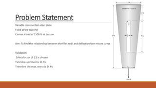
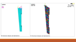
1) The document presents the results of a 3D structural analysis and optimization of a variable cross-section steel plate fixed at the top end and carrying a 1500 lb load at the bottom.
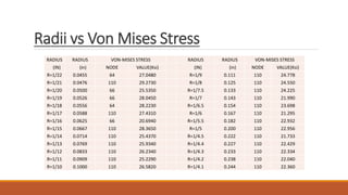
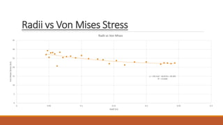
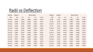
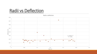
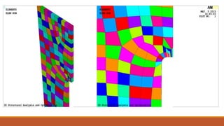
2) The analysis examined the relationship between fillet radii and deflection/von misses stress in the plate.
3) The results show relationships between fillet radii and von mises stress and deflection, with R-squared values indicating a moderate fit. Areas for improving the model are identified.