This document discusses reliability modeling and evaluation. It defines systems and describes two types: non-maintained and maintained. For non-maintained systems, reliability and mean time to failure are key metrics, while for maintained systems availability and mean time to repair are more important. The document also discusses different modeling approaches like black box, white box, and graphical representations. It covers reliability modeling concepts like independent failures, various system models including series, parallel and k-out-of-n configurations.
![01-02-2012
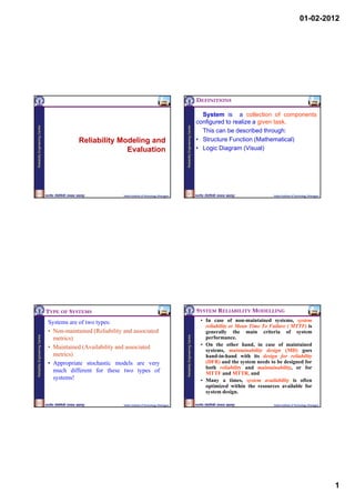
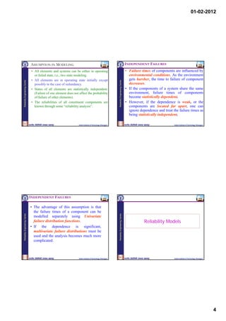
VARIOUS SYSTEM MODELS Series & Parallel Systems
Now we will consider various system Series System Parallel System
models that can be built for a given
non-redundant system fully redundant system
situation. Among these system models are
Reliability Engineering Centre
Reliability Engineering Centre
(all components must work for (all components must fail for system
series, parallel, series-parallel and system success) failure)
parallel-series, k-out-of-m:G, standby, ,
TR1, 10 kVA TR1, 20 kVA
partial standby , non-series parallel model 15 kVA 15 kVA
etc. We will consider these one by one and Load Load
derive system reliability and system MTTF TR2, 10 kVA TR2, 20 kVA
for these configurations.
1
1 2
2
18
Indian Institute of Technology, Kharagpur Indian Institute of Technology, Kharagpur
Series System Example:
Let R = P [Success] A system consists of 10 identical components, all of
1 2 Q = P [Failure] which must work for system success. What is the
system reliability if each component has a reliability of
R+Q=1
Reliability Engineering Centre
Reliability Engineering Centre
0.95?
R s R1 R 2
n Qs 1 R S Component reliability, R = 0.95
Ri
i 1
1 R1 R 2 Number of components, n = 10
components
product rule of reliability 1 - (1 - Q1 )(1 Q 2 )
Using Product Rule of Reliability,
Q1 Q 2 Q 1 Q 2
S System Reliability, Rs = Rn
S = (0.95)10 = 0.5987
R1 R2
Q1 Q2
20
19
Indian Institute of Technology, Kharagpur Indian Institute of Technology, Kharagpur
5](https://image.slidesharecdn.com/3-reliabilitymodelling-120425085622-phpapp02/85/3-reliability-modelling-5-320.jpg)
![01-02-2012
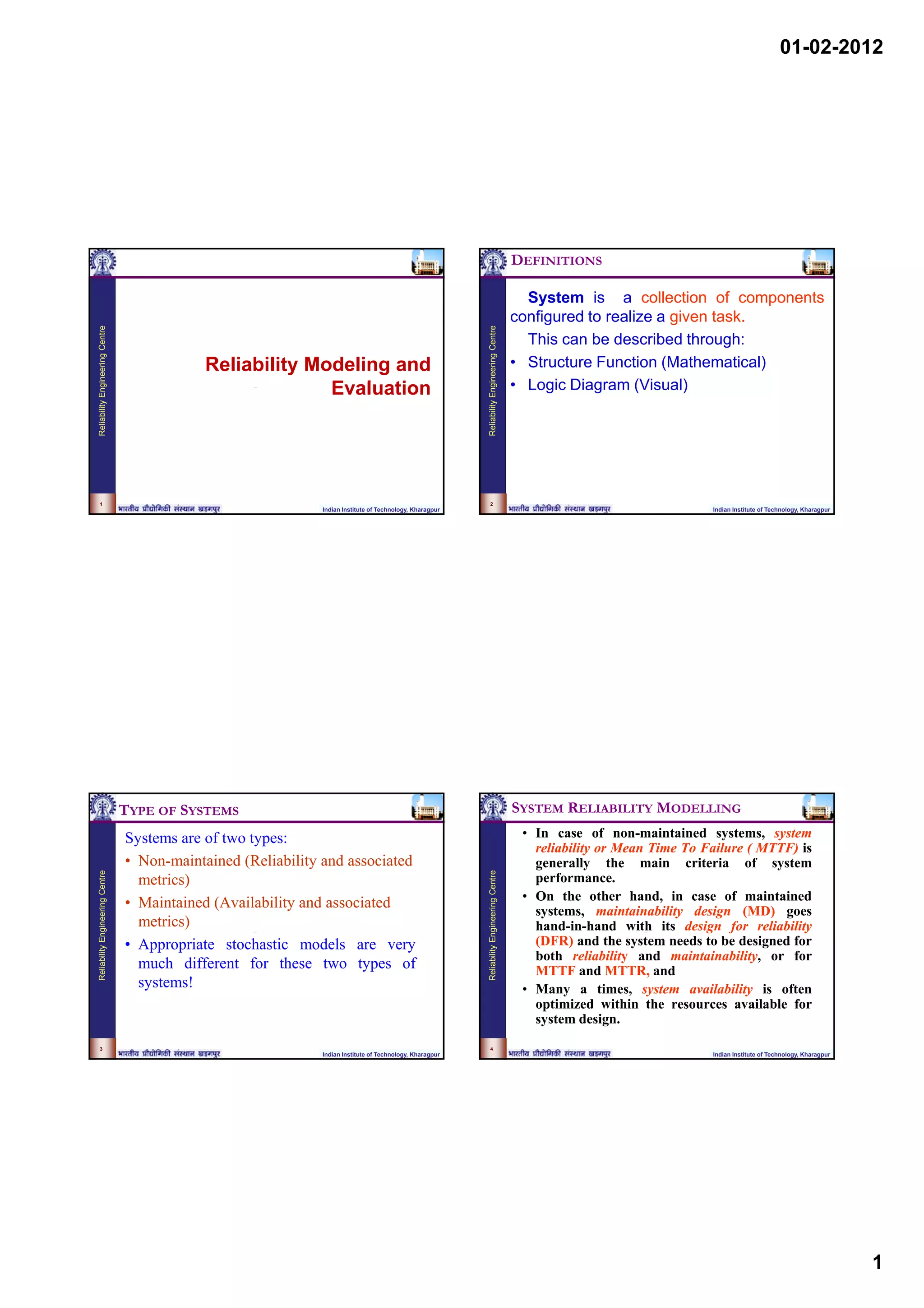
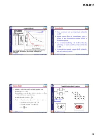
Series/Parallel Systems Example:
Telcom. Repeater DG Rectifier Derive a general expression for the unreliability of the
Station 2 3 model shown below, and hence evaluate the unreliability of
1 the system if all components have a reliability of 0.8.
Reliability Engineering Centre
Reliability Engineering Centre
Power Supply
4 Cable
System
Battery Bank
Network Reduction p
Output
input
Technique
RX = R2.R3 X
1
QY = QX.Q4 4
RY = 1 - QX.Q4 Reliability Network Model (Reliability Block Diagram)
= 1 – (1-RX).(1-R4) of the System
Y 1
RS = RY.R1
29 30
29 30
Indian Institute of Technology, Kharagpur Indian Institute of Technology, Kharagpur
m out of n Systems
Ri = 0.8 for i = 1 to 5 partially redundant system
TR1, 10 kVA
If components are identical then
Reliability Engineering Centre
Reliability Engineering Centre
3 3 2 2 3
15 kVA (R + Q) = R + 3R Q + 3RQ + Q
Load Rs = R 3 + 3R2Q
TR2, 10 kVA
Qs = 3RQ2 + Q3 = 1 - Rs
TR3, 10 kVA If components are non-identical then
Q 8 = Q 7 . Q5
= (1 - R7). Q5 2 out 3 system R1 R2 R3
= (1 - R1 . R2 . R6). Q5 2/3
= [1 - R1 . R2 . (1 - Q6)]. Q5 1 Rs = R1 R2 R3 +
= [1 - R1 . R2 . (1 - Q3 . Q4)]. Q5 R1 R2 Q3 + R1 Q2 R3 + Q1 R2 R3
2
Q8 = [1 – 0.8 x 0.8 (1 – 0.2 x 0.2)]x 0.2 = 0.07712
31 3 32
31 32
Indian Institute of Technology, Kharagpur Indian Institute of Technology, Kharagpur
8](https://image.slidesharecdn.com/3-reliabilitymodelling-120425085622-phpapp02/85/3-reliability-modelling-8-320.jpg)
![01-02-2012
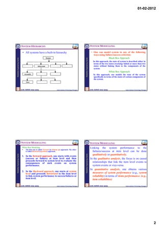
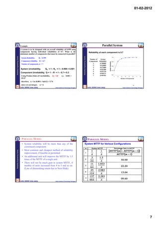
Example: 2/3
4
2
Derive a general expression for the unreliability of the system 1 5
whose reliability model is shown below. Consider the case in 3 6
which all parallel branches of this system are fully redundant 7
Reliability Engineering Centre
Reliability Engineering Centre
with the exception of that consisting of components 4, 5 and 6 for
Q8 = Q2 . Q3
which any 2 of the branches are required for system success.
1 8 9 If Components 4, 5 and 6 are identical, each with
2/3 reliability R, R9 = R3 + 3R2Q
4
2 7
Otherwise
1 5 R 9 = R 4 R 5 R 6 + R 4 R 5 Q 6 + R 4 Q 5 R 6 + Q4 R 5 R 6
input 3 Output
6 10
R10 = R1 R8 R9
7
7
Qs = Q10 . Q7
= (1 – R10). Q7
Reliability Network Model (Reliability Block = (1 - R1 . R8 . R9). Q7
11 = [1 - R1 (1 – Q8).R9 ]. Q7
Diagram) of the System
33 = [1 - R1 (1 – Q2 .Q3). R4 R5 R6 + R4 R5 Q6 + R4 Q5 R6 + Q4 R5 R6 ]. Q7
34
Indian Institute of Technology, Kharagpur Indian Institute of Technology, Kharagpur
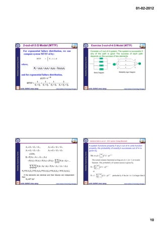
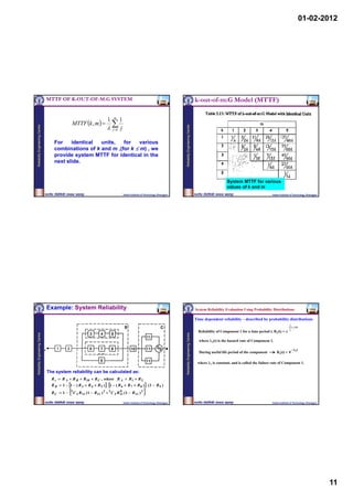
2-out-of-3:G Model RELIABILITY OF 2-OUT-OF-3:G SYSTEM
The Reliability Logic Diagram and Fault Tree diagram for Let us designate the paths in Block diagram as
2-out-of-3:G system are shown below: Obviously, T1 , T2 and T3 .
Reliability Engineering Centre
Reliability Engineering Centre
T1 E1 E 2 , T2 E1 E3 and T3 E 2 E3
where Ei is the event of unit i being good. Therefore,
system reliability is given by:
Rs PrT1 T2 T3 PTi PTi T j PTi T j Tk
3
i 1 i j i j k
where,
PT1 T2 PE1 E 2 E1 E3 PE1 E 2 E3
3
3 3
Rs P Ti P E1 E2 E3 PE1 E2 E3
i 1 2 3
R s p1 p 2 p1 p 3 p 2 p 3 2 p1 p 2 p 3
35
or R s 3 p 2 2 p 3 .
Indian Institute of Technology, Kharagpur Indian Institute of Technology, Kharagpur
9](https://image.slidesharecdn.com/3-reliabilitymodelling-120425085622-phpapp02/85/3-reliability-modelling-9-320.jpg)
![01-02-2012
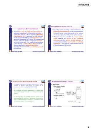
Series Systems Parallel Systems
1
1 2 Rs = R1 . R2 product rule of reliability Qs = Q1 . Q2 product rule of unreliability
2
Considering time dependent probabilities,
Reliability Engineering Centre
Reliability Engineering Centre
t
λ 1 (t)dt
t
λ 2 (t)dt
Considering time dependent probabilities, t t
λ 1 (t)dt λ 2 (t)dt
Rs(t) = R1(t). R2(t) = e 0
e 0
Qs(t) = Q1(t). Q2(t) = [1- e 0 ].[1- e 0
]
For ‘n’ component series system with hazard rates 1(t), 2(t), …, n(t), For ‘n’ component parallel system with hazard rates 1(t), 2(t), …, n(t),
t
n t n λ i (t)dt
also applicable if failure distributions for
Qs(t) = [1 - e
λ i (t)dt
Rs(t) = e 0
different components are different
0
]
i 1 i 1
During useful life period when component failures are exponentially During useful life period when component failures are exponentially
distributed distributed
n n
cannot obtain equivalent hazard rate for
Qs(t) = [1 - e i ]
n
λ t
n λit where equivalent hazard rate, e = i
Rs(t) = e
λ it et exponential distribution
= e i 1
= e i 1
i 1
is also constant i 1
Therefore, resulting distribution for the system is non-exponential
i.e. resulting distribution for the system is also exponential i.e. resulting hazard rate for the system is no longer constant, but a function
Indian Institute of Technology, Kharagpur
of time Indian Institute of Technology, Kharagpur
Partially Redundant (m out of n) Systems Example:
Apply Binomial Expansion A simple electronic circuit consists of 6 transistors each having a failure
rate of 10-6 f/hr, 4 diodes each having a failure rate of 0.5 x 10⁻⁶ f/hr, 3
n capacitors each having a failure rate of 0.2 x 10⁻⁶ f/hr, 10 resistors each
[R(t) + Q(t)] n = nCr R(t) n-r Q(t) r having a failure rate of 5 x 10⁻⁶ f/hr and 2 switches each having a failure
Reliability Engineering Centre
Reliability Engineering Centre
r0
rate of 2 x 10⁻⁶ f/hr. Assuming connectors and wiring are 100% reliable,
During useful life period when component failures are evaluate the equivalent failure rate of the system and the probability of
the system surviving 1000 and 10000 hours if all components must
exponentially distributed operate for system success. n
λt eλt Equivalent failure rate of the system, e = i1
i
R(t) = e and Q(t) = 1 -
= 6(10-6 ) + 4(0.5 x 10⁻⁶ ) + 3(0.2 x 10⁻⁶ ) + 10(5 x 10⁻⁶ ) + 2(2 x 10⁻⁶ ) = 6.26 x 10⁻⁵
f/hr
Let see some simple examples. t 6.26 x 10 6
x1000
Rs(1000 hr) = e e = e = 0.9393
et 6.26 x 10 6 x10000
Rs(10,000 hr) = e = e = 0.5347
Indian Institute of Technology, Kharagpur Indian Institute of Technology, Kharagpur
12](https://image.slidesharecdn.com/3-reliabilitymodelling-120425085622-phpapp02/85/3-reliability-modelling-12-320.jpg)
![01-02-2012
Example:
Standby Model
Consider a system comprising of 4 identical units each having a failure
One or more units are in standby mode waiting to take over
rate of 0.1 f/yr. Evaluate the probability of the system surviving 0.5 years
and 5 years if at least two units must operate successfully. the operation from the main operating unit as soon as the
failure of the operating unit takes place.
Reliability Engineering Centre
Reliability Engineering Centre
Using Binomial Expansion, Decision switch senses the failure of the basic unit.
[R(t) + Q(t)] 4 = R4(t) + 4 R3(t)Q(t) + 6 R2(t)Q2(t) + 4 R(t)Q3(t) + Q4(t) It is assumed that the operation of failure sensing and
where, R(t) = e
λt
and Q(t) = 1 -
eλt switching on to the standby unit is instantaneous, i.e.,
operation.
uninterrupted system operation
For 2 out of 4 system, The standby system fails only when all the system units
Rs(t) = R4(t) + 4 R3(t)Q(t) + 6 R2(t)Q2(t) including the standby units have failed.
The reliability of such system will be higher than the
4 λt 3 λt λt 2 λt λt 2
=e +4e (1 - e ) + 6 e (1 - e ) parallel system with equal number of active units.
(Conditions?).
For t = 0.5 years, t = 0.1 x 0.5 = 0.05 Rs(0.5) = 0.9996
For t = 5 years, t = 0.1 x 5 = 0.5 Rs(5) = 0.8282
50
Indian Institute of Technology, Kharagpur Indian Institute of Technology, Kharagpur
STANDBY MODELS STANDBY MODELS: MISSILE SYSTEM
Reliability Engineering Centre
Reliability Engineering Centre
Indian Institute of Technology, Kharagpur Indian Institute of Technology, Kharagpur
13](https://image.slidesharecdn.com/3-reliabilitymodelling-120425085622-phpapp02/85/3-reliability-modelling-13-320.jpg)
![01-02-2012
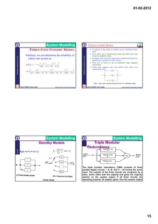
System Modelling System Modelling
Two Unit Standby Model Two Unit Standby Model
Obviously, from the Fig (b), it
can be seen easily that the Therefore, reliability for a two-unit standby
system success would be system would be obtained as:
Reliability Engineering Centre
Reliability Engineering Centre
obtained:
Either (i) when the primary unit #
Rs ( t ) Pr[(t1 t) {(t1 t) ( t 2 t t1 )} ]
1 continues to work beyond or t
the mission time t, i.e., t1 > t, p 1 t f 1 t 1 p 2 t t 1 dt 1
where t1 is the time to failure 0
of unit # 1.
or (ii) unit # 1 fails at time t1 (t1< p1 t e 1t f 1 t1 1e 1t1 p 2 t t1 e 2 t t1
t), and the standby unit ( unit
# 2) comes into operation t
immediately upon the failure R s t R 1 R 2 e 1t 1 e
1t
e 2 t t1 dt 1
of unit #1 and continues to 0
work for t2 > (t-t1). The system reliability e 1t e 2 t
therefore can be given Rs t e 1t 1
by: 2 1 1 2
Rs ( t ) Pr[(t1 t){(t1 t)( t2 t t1 )}] Indian Institute of Technology, Kharagpur Indian Institute of Technology, Kharagpur
STANDBY MODELS: IMPERFECT SWITCH STANDBY MODELS: OTHER
The function of decision switch (DS) is critical and the DS perfect but Degradation of standby unit
success of a standby system to great extent depends in standby mode.
upon the reliability of this decision switch. Combining degradation of standby unit and
Reliability Engineering Centre
Reliability Engineering Centre
Imperfect switching
The reliability decision switch is driving the system
reliability.
Two-unit standby system ,
Rs (t ) P[(t1 t ) {(t1 t ) (t ds t1 ) (t 2 t t1 )}]
t
R S ( t ) p 1 ( t ) p ds
0
f 1 ( t 1 ) p 2 ( t t1 ) dt 1
tds represents a random variable denoting the time to
failure of the decision switch.
55 56
Indian Institute of Technology, Kharagpur Indian Institute of Technology, Kharagpur
14](https://image.slidesharecdn.com/3-reliabilitymodelling-120425085622-phpapp02/85/3-reliability-modelling-14-320.jpg)
![01-02-2012
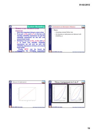
System Modelling System Modelling
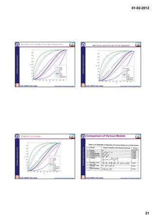
Triple Modular SHARED LOAD MODEL
Redundancy
However, if one element has failed so that it has produced an A model in which the load on a member
incorrect output, the voter chooses the output of the two changes and consequently the hazard rate of
Reliability Engineering Centre
Reliability Engineering Centre
good elements as the system output because they both the member also changes, as one or more
agree; thus the system output is correct. If two elements have member fail.
failed, the voter agrees with the majority (the two that have In this model all the units/sub-systems are
failed); thus the system output is incorrect. The system connected in parallel and each unit shares the
output is also incorrect if all three circuits have failed. load equally.
Actually, circuits-A, B, and C- in most cases are identical and After the failure of one or more units the
they are three replications of the same design. Using this remaining units share the load equally but with
assumption, and also assuming that the voter does not fail a higher value of hazard rate.
and all digital circuits are independent and identical with The levels of hazard rate change only when a
probability of success p,3the system reliability is given by: subsystem failure occurs.
R s p 3 1 p p 2 1 p 3 p 2 p p 3 2 p
3
0 1 2 3 2
It is assumed that failure distribution of the
3 2 survivor subsystem after failure of a
Indian Institute of Technology, Kharagpur Indian Institute of Technology, Kharagpur
subsystem does not depend on the interval of
System Modelling System Modelling
TWO UNIT SHARED LOAD MODEL TWO UNIT SHARED LOAD MODEL
In this case, we will have two units sharing the Let,
Reliability Engineering Centre
Reliability Engineering Centre
given load equally however if one unit fails, the fh(t) : be the p.d.f. for time to failure of a unit
total load will have to be take over by the single under half load condition
unit as shown in the following figure. ff(t) : be the p.d.f. for time to failure of a unit
under full load condition( this occurs
Half load
when one unit fails and other unit is forced
to take the full load )
Half load
Therefore the system is successful if,
1. Both component remain operational until the
mission time. The probability of this is given
Full load by:
P[(t1>t)∩(t2>t)] = {ph(t)}2
Where, ph(t) is reliability of a unit under half
Indian Institute of Technology, Kharagpur load Indian Institute of Technology, Kharagpur
16](https://image.slidesharecdn.com/3-reliabilitymodelling-120425085622-phpapp02/85/3-reliability-modelling-16-320.jpg)
![01-02-2012
System Modelling System Modelling
TWO UNIT SHARED LOAD MODEL TWO UNIT SHARED LOAD MODEL
2. The first unit fails and the second unit survives and Now the system reliability is found by adding the
Reliability Engineering Centre
Reliability Engineering Centre
the takes the full load (after the failure of the first probabilities of case 1 , case 2 and case 3 i.e.
unit) until the time t, The probability of this
operation is given by:
P[(t1≤t, under half load)∩(t2>t1, under half load)∩ If we assume the failure distribution to the
exponential distribution for both the units and
( t2>t-t1, under full load)] = denote the failure rates at half and full load by λh
and λf respectively. Then the reliability expression
3. This is identical to the case 2 the only difference is can be written as, t
2 h e f
R s t e 2 h t
that here unit 2 fails and unit 1 take the full load(
after failure of the second unit) and the probability [1 e ( 2 h f ) t ]
of this operation can be found by replacing t1 by t2 . (2 h f )
Incase both the units are same the probabilities
in case 2 and case 3 turns out to Institute of Technology, Kharagpur
Indian
be same. Indian Institute of Technology, Kharagpur
System Modelling System Modelling
THREE UNIT SHARED LOAD THREE UNIT SHARED LOAD
SYSTEMS SYSTEMS
Similarly the reliability expression for the three The diagrammatic representation of the load
Reliability Engineering Centre
Reliability Engineering Centre
unit shared load model can be derived, the shifting is shown below,
1/3 load
success probability versus time plot is shown
below, #1
Su
E1∩E2∩E3
1/3 load
cce #2 E1∩E2∩E3
ss E 1 E 2 E3
1/3 load
E1∩E2∩E3
Pro #3 E1 E 2 E 3
ba E1 E 2 E 3 1/2 load
bili
ty 1/2 load
t1 t2
Time t
Full load
Indian Institute of Technology, Kharagpur Indian Institute of Technology, Kharagpur
17](https://image.slidesharecdn.com/3-reliabilitymodelling-120425085622-phpapp02/85/3-reliability-modelling-17-320.jpg)
![01-02-2012
System Modelling System Modelling
THREE UNIT SHARED LOAD THREE UNIT SHARED LOAD
SYSTEMS SYSTEMS
For three similar units the above possibilities P(#2) = 3P[(t1≤t,at 1/3 load)∩{(t2>t1) ∩(t3>t1), at 1/3
Reliability Engineering Centre
Reliability Engineering Centre
can be described as, load}∩ {(t2>t-t1) ∩(t3>t-t1), at ½ load}]
1. All the three units operate until the mission And
time and share the load equally. P(#3) = 6P[(t1≤t, at 1/3 load) ∩{(t2>t1) ∩(t3>t1), at 1/3
2. Unit #1 fails and the other two units survive }
load}
and share the load equally. ∩{(t2≤t, at ½ load) ∩(t3>t2, at ½ load)} ∩
3. Unit #1 and Unit #2 fail and Unit #3 operates {(t3>t-t1-t2), at full load}
Now the reliability expression for the three unit shared load model can
and is forced to take the full load. be written as,
Let t1, t2 and t3 be the time to failure of the Rs(t) = P(#1) + P(#2) + P(#)
first, second and third unit respectively then
the probabilities of the above possibilities can
be written as,
P(#1) = P[(t1>t)∩(t2>t) ∩(t3>t)] = [po(t)]3
Indian Institute of Technology, Kharagpur Indian Institute of Technology, Kharagpur
System Modelling System Modelling
THREE UNIT SHARED LOAD THREE UNIT SHARED LOAD
SYSTEMS SYSTEMS
In the integral form it can be written as, The expression comes out to be,
Reliability Engineering Centre
Reliability Engineering Centre
t
Rs(t) = [po(t)]3 + 3 f o t 1 { p o t 1 } { p h ( t t 1 )} dt 1
2 2
3o
+ 0 Rs (t) e3ot (e3ot e2ht )
t t t1
(2h 3o )
6 f o t 1 { p o t 1 } 2 f h ( t 2 ) p h ( t 2 )p f ( t t 1 t 2 )dt 2 dt 1
0 0
e3ot e2ht
Now if we take the failure distribution to be 6oh[
exponential distribution with failure rates λo, λh (3o 2h )(3o f ) (2h 3o )(2h f )
and λf for the 1/3, ½ and full load respectively then
t
the reliability expression can be written as, e f
]
Indian Institute of Technology, Kharagpur
(f 3o )(f 2h ) Indian Institute of Technology, Kharagpur
18](https://image.slidesharecdn.com/3-reliabilitymodelling-120425085622-phpapp02/85/3-reliability-modelling-18-320.jpg)
![01-02-2012
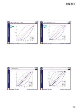
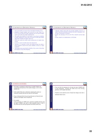
The system will be good if:
Two units shared load Model:
Two units are sharing given
load equally. However if a unit 1. Both components remain in operational mode until the mission
fails, the total load will have to be E1∩E2 time.
Reliability Engineering Centre
Reliability Engineering Centre
#1
taken over by a single unit.
Success E1∩E2
probabilities
The probability of this given by,
E1∩E2
#2
P[t1>t∩t2>t]={ph (t)}2
Let (t) be h d f for
L fh( ) b the p.d.f. f t1 t
time to failure of a unit under half Time Where, ph (t) is reliability of a unit at half load condition
load condition. i.e.
Success probabilities of two unit
shared load system p h (t )
t
f h ( u ) du
Let ff(t)be the p.d.f. for time t1 and t2 are time to failure of two units and the ‘t’ is mission time.
to failure of a unit under full load
condition.
89 90
Indian Institute of Technology, Kharagpur Indian Institute of Technology, Kharagpur
3 This is like 2 but instead of the first unit failing fist, the second
unit is fails first and the other survives until time t.
2 Unit 1 is failed at time t1 , and prior to this the units are taking
half of the load each. After time t1 ,unit 2 alone takes the full
Reliability Engineering Centre
Reliability Engineering Centre
load until time t. the probability of this operation
the probability of this operation ,
P[(t 2 t , under half load ) (t1 t 2 , under half load )
P[( t1 t , under half load ) (t 2 t1 , under half load ) (t1 t t 2 , under full load )]
( t 2 t t1 , under full load )] t
f h (t 2 ) ph (t 2 ) p f (t t 2 ) dt 2
t
0
f h (t1 ) ph (t1 ) p f (t t1 ) dt1
0 System Reliability = [ sum of the probabilities of earlier three
equations]
where p f (t ) f f (u ) d (u ) t
t
RS [ ph (t )]2 2 f h (t1 ) ph (t1 ) p f (t t1 ) dt1
0
91 92
Indian Institute of Technology, Kharagpur Indian Institute of Technology, Kharagpur
23](https://image.slidesharecdn.com/3-reliabilitymodelling-120425085622-phpapp02/85/3-reliability-modelling-23-320.jpg)