Downloaded 35 times


![5-14 2000 Family / Guide to Installation, Troubleshooting, and Maintenance
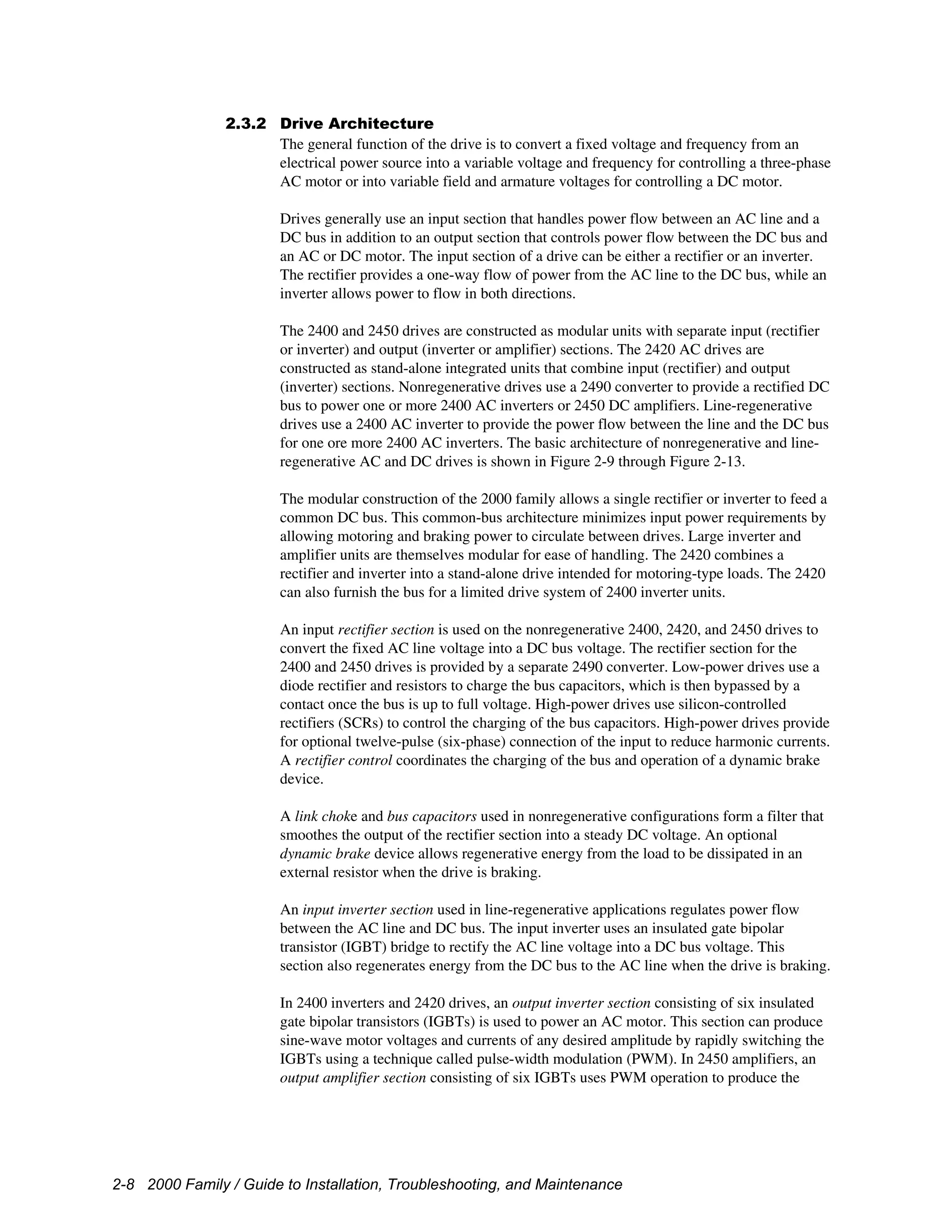
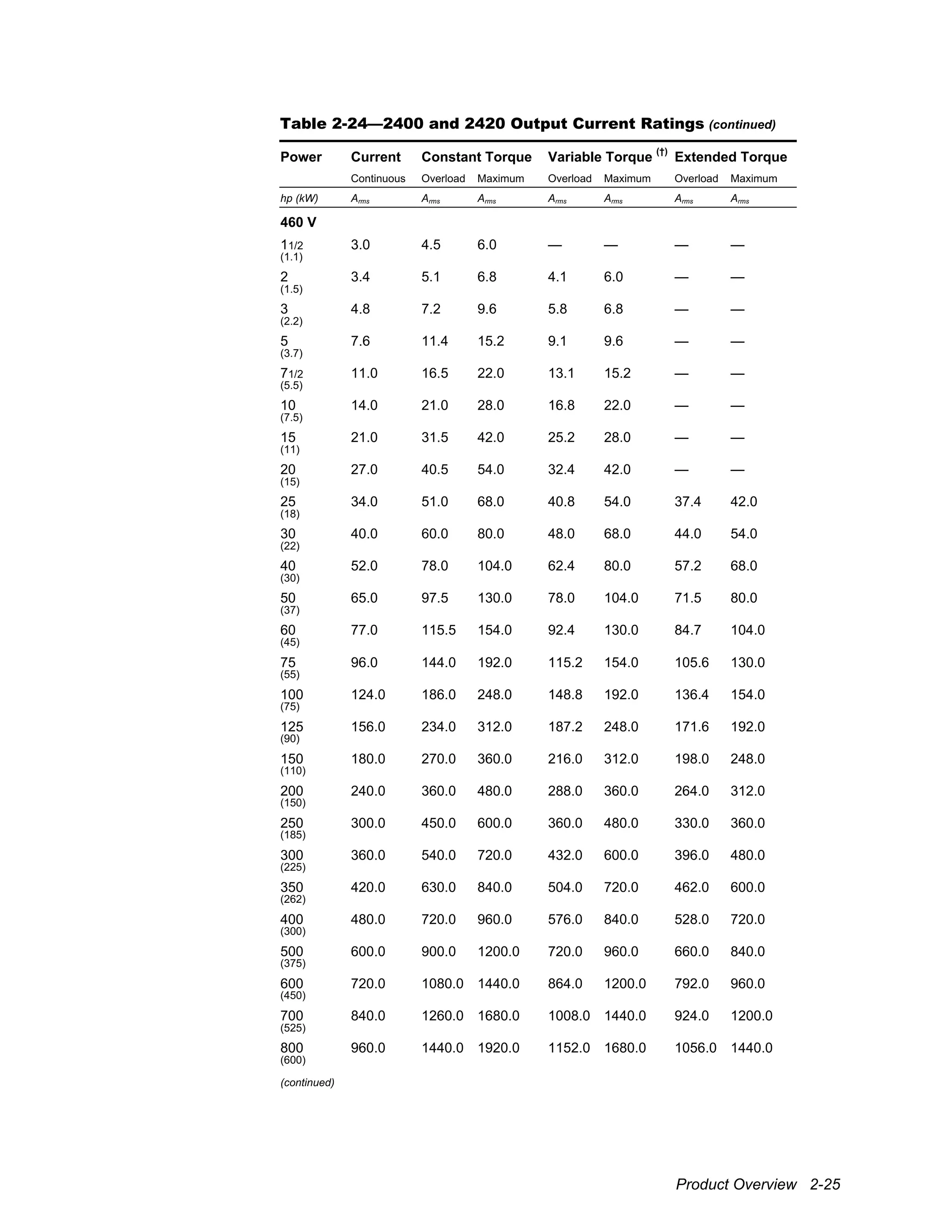
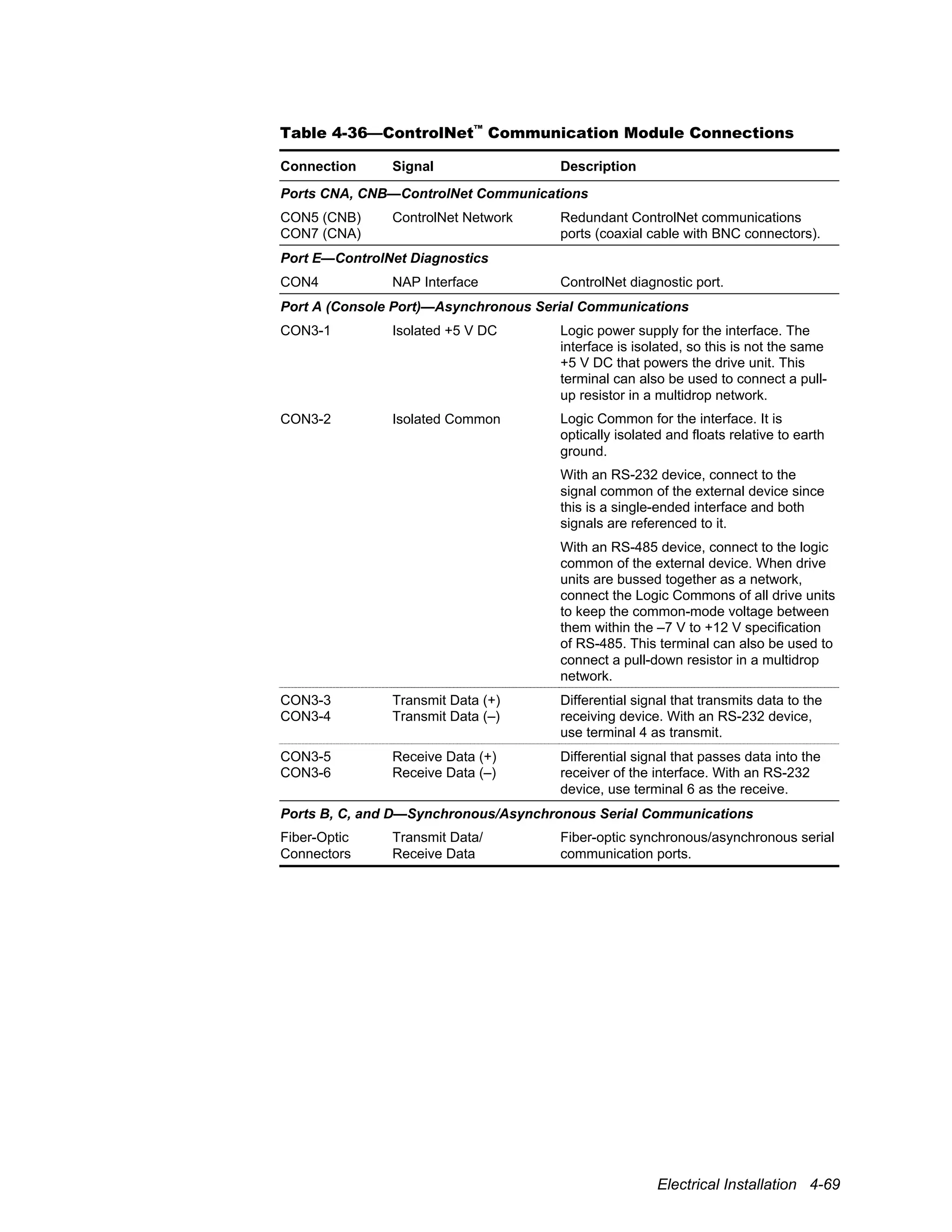
5.2.2 Rectifier Checking Procedure (2420 and 2490)
The rectifier bridge diodes or SCRs can be checked using a multimeter set on diode range
by following the procedure outlined below.
!
Attention
To avoid an electrical shock hazard and possible damage to the equipment,
follow all safety instructions listed in the front of this manual, beginning on
page i.
[1] Remove power
Lock off the incoming power at the main machine disconnect switch. Use an
appropriate meter to verify that all DC bus capacitor banks have been discharged
to zero volts before proceeding. Set the meter to DC voltage and read across
terminals B+ and B–. The reading should be 0 V before any attempt is made to
work on the unit.
[2] Disconnect power board
Disconnect all wires from terminals R, S, and T. If the converter is diode-based
(2420 and Form 2 2490 units), disconnect bridge rectifier leads B+ and B– from
the diodes.
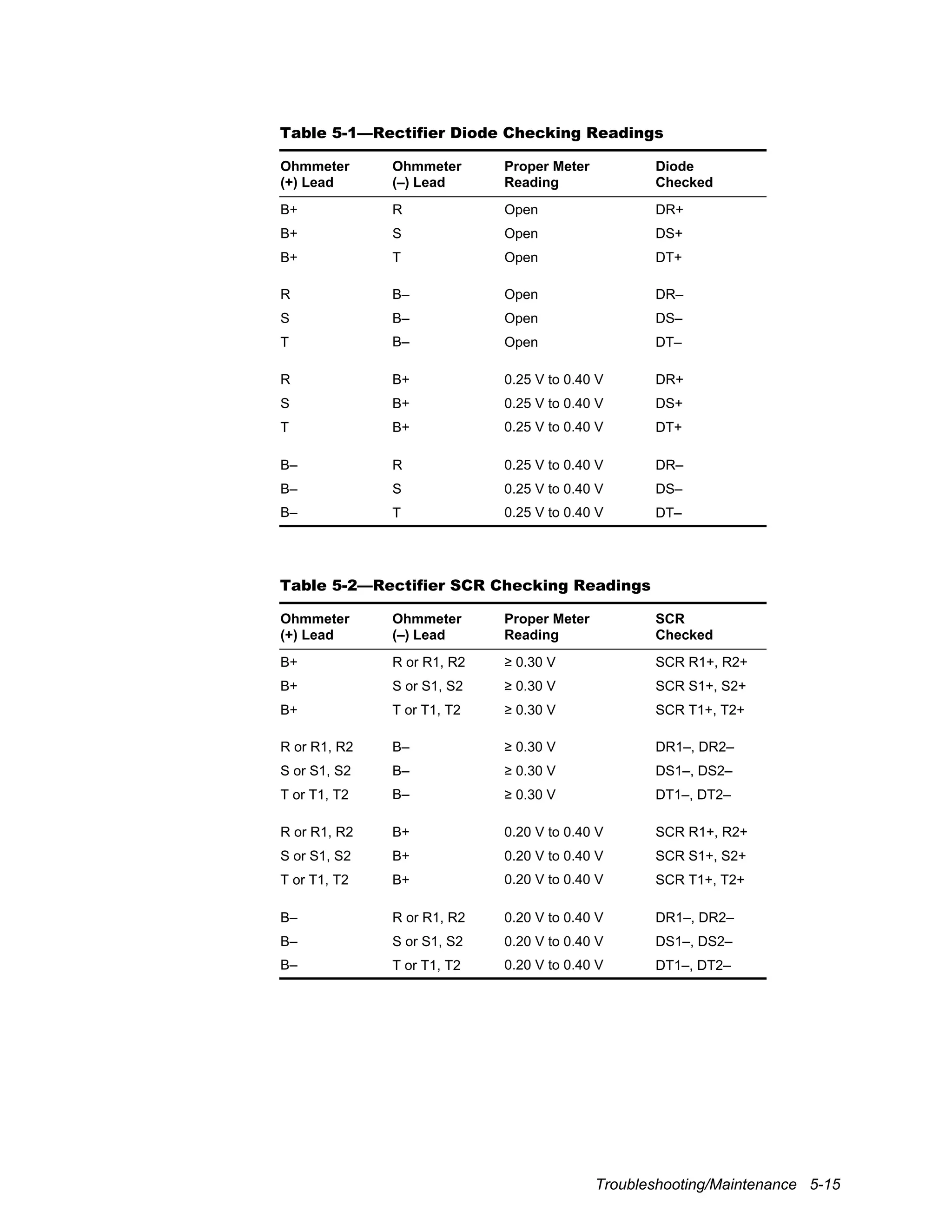
[3] Take readings
Using a digital ohmmeter set on diode range, take each of the readings indicated
in either Table 5-1 (for diode-based converters) or Table 5-2 (for SCR-based
converters). Compare the readings with the proper values indicated in the table.
[4] Replacement
Any meter reading other than that specified indicates a defective diode or SCR.
Replace the defective component or the entire unit.
[5] Reconnect
When the test is complete, replace all wires to terminals R, S, and T. For diode-
based units, replace the B+ and B– bridge rectifier leads as well.](https://image.slidesharecdn.com/2400manual-190128202139/75/2400-manual-158-2048.jpg)
![5-16 2000 Family / Guide to Installation, Troubleshooting, and Maintenance
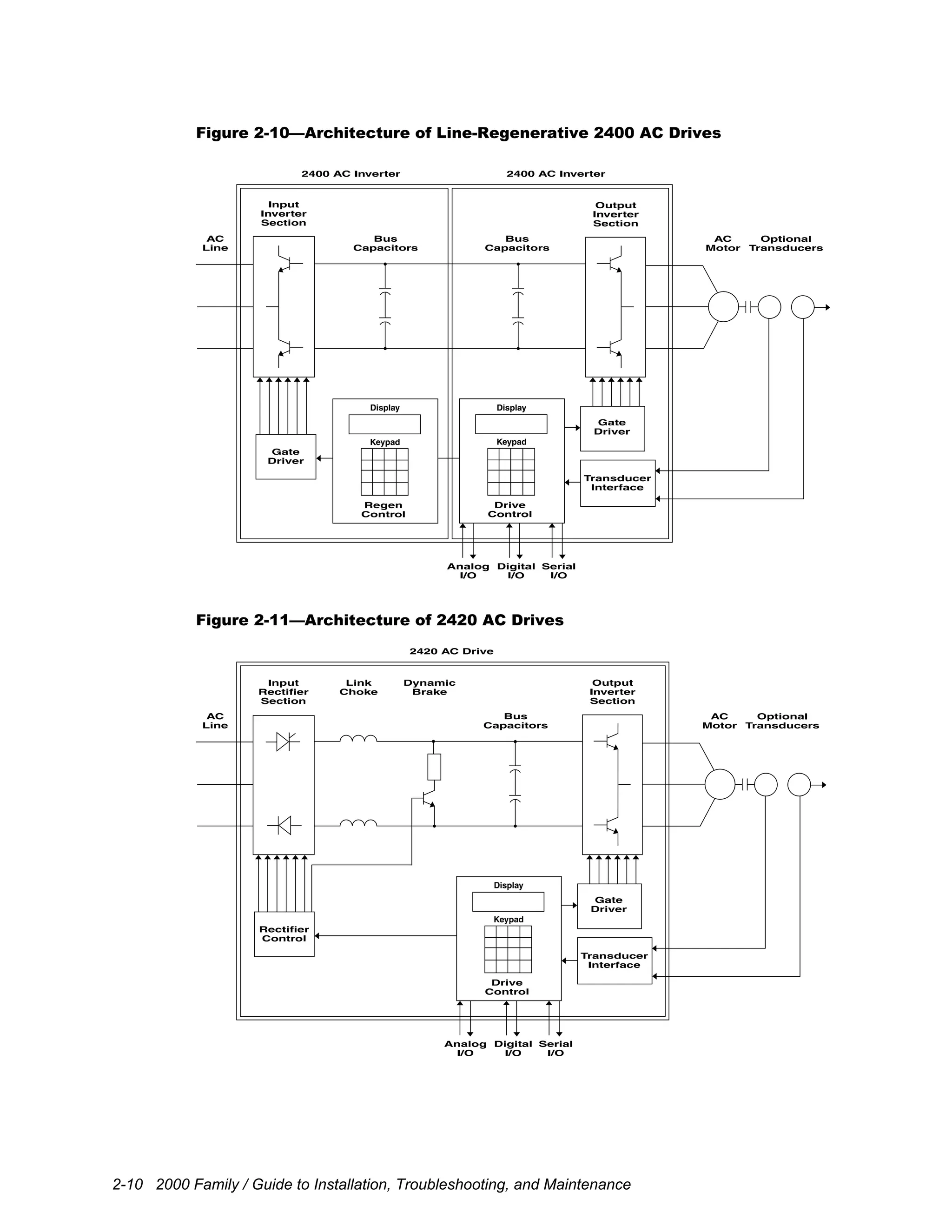
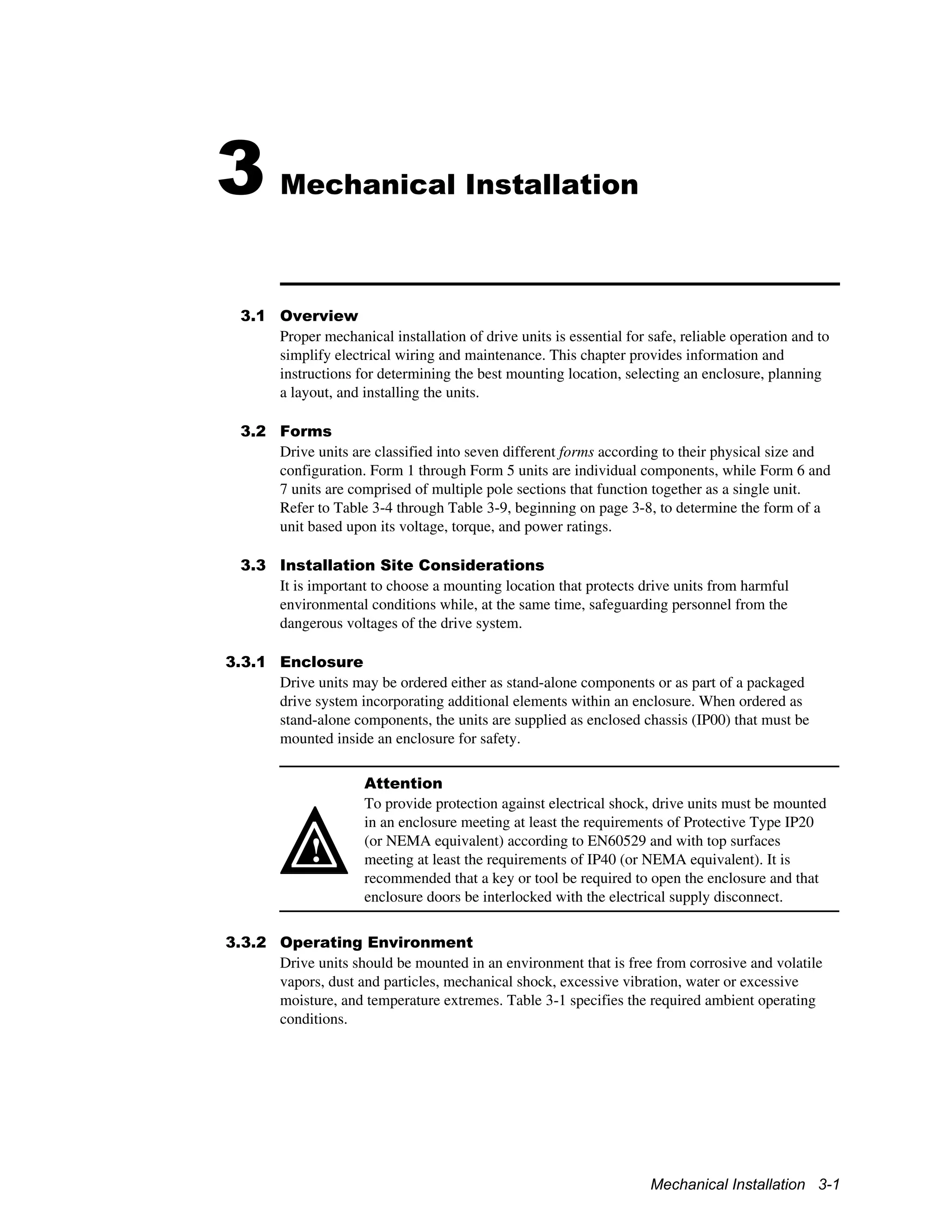
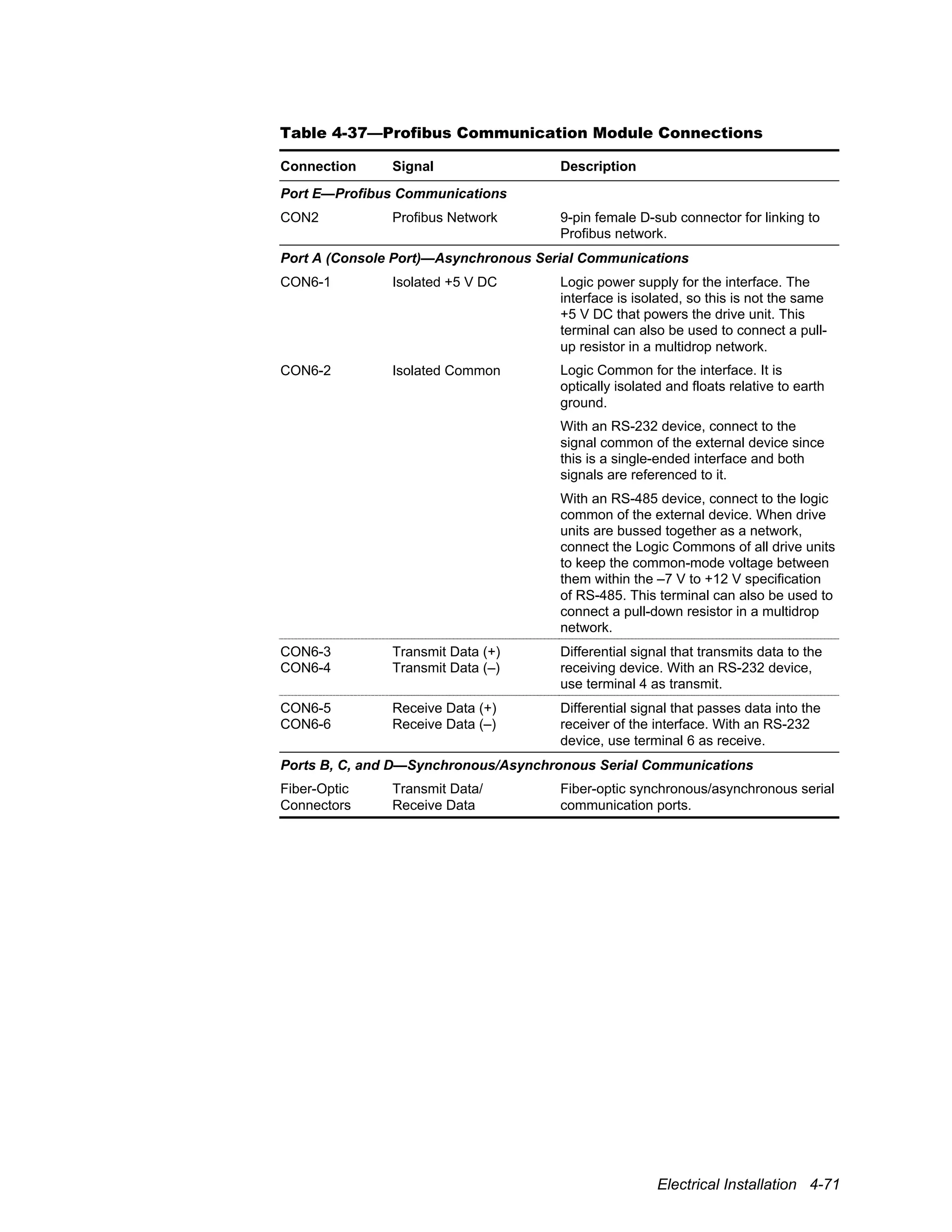
5.2.3 Transistor Checking Procedure (2400 and 2420)
The inverter IGBTs can be checked using a multimeter set on diode range by following
the procedure outlined below.
!
Attention
To avoid an electrical shock hazard and possible damage to the equipment,
follow all safety instructions listed in the front of this manual, beginning on
page i.
[1] Remove power
Lock off the incoming power at the main machine disconnect switch. Use an
appropriate meter to verify that all DC bus capacitor banks have been discharged
to zero volts before proceeding. Set the meter to DC voltage and read across
terminals B+ and B–. The reading should be 0 V before any attempt is made to
work on the inverter.
[2] Disconnect wires
Disconnect all wires from terminals D+ (on 2420 units), U, V, and W and
remove the inverter bridge B+ and B– leads from the transistors. Do not remove
the bus links that go between the converter and the inverter.
[3] Take readings
Using a digital ohmmeter on diode range, take each of the readings indicated in
Table 5-3. Compare the readings with the proper values indicated in the table.
[4] Replacement
Any meter reading other than that specified indicates a defective transistor or
diode. Replace the defective transistor or diode package or the entire unit.
[5] Reconnect
When the test is complete, replace all wires to terminals D+, U, V, and W as
well as to the inverter bridge B+ and B– leads.](https://image.slidesharecdn.com/2400manual-190128202139/75/2400-manual-160-2048.jpg)


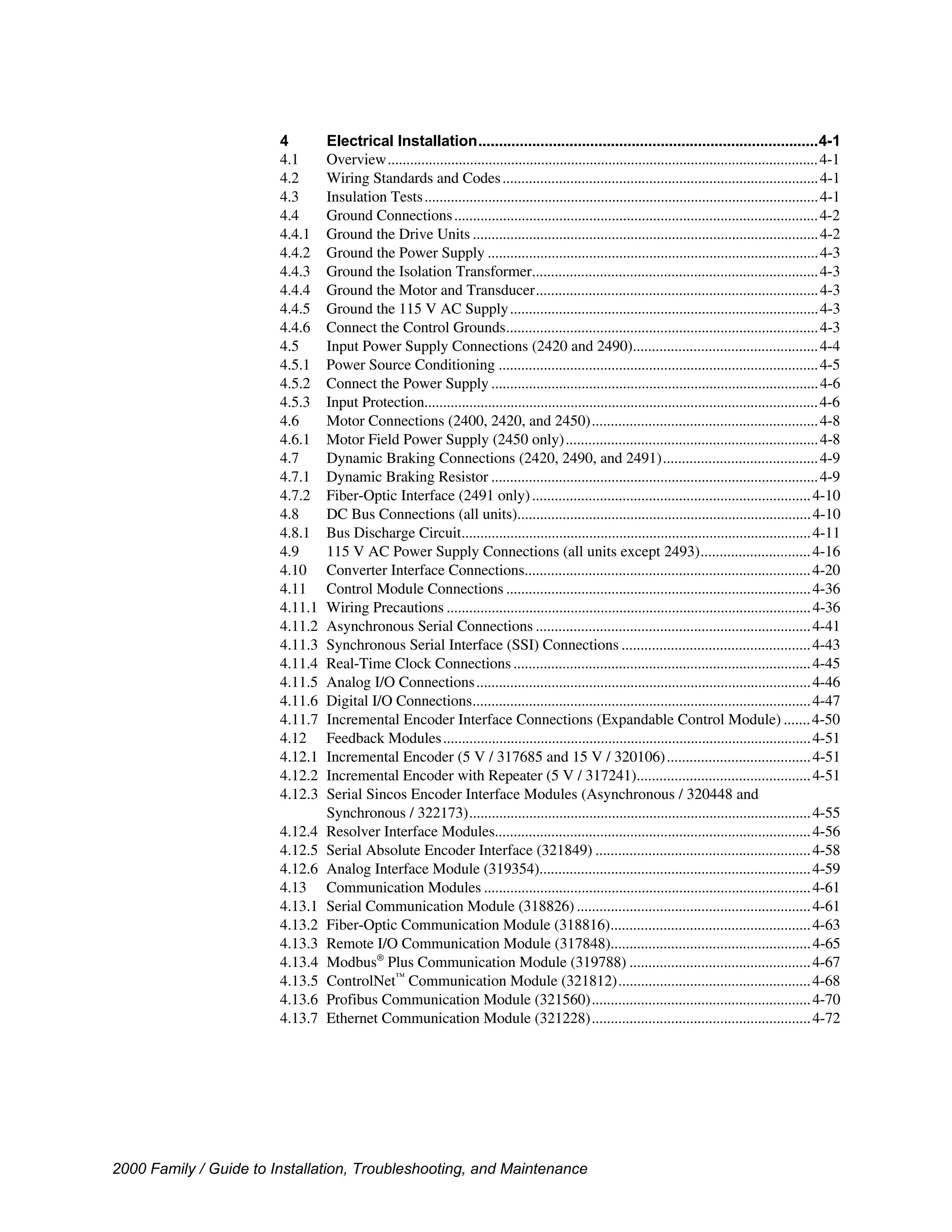
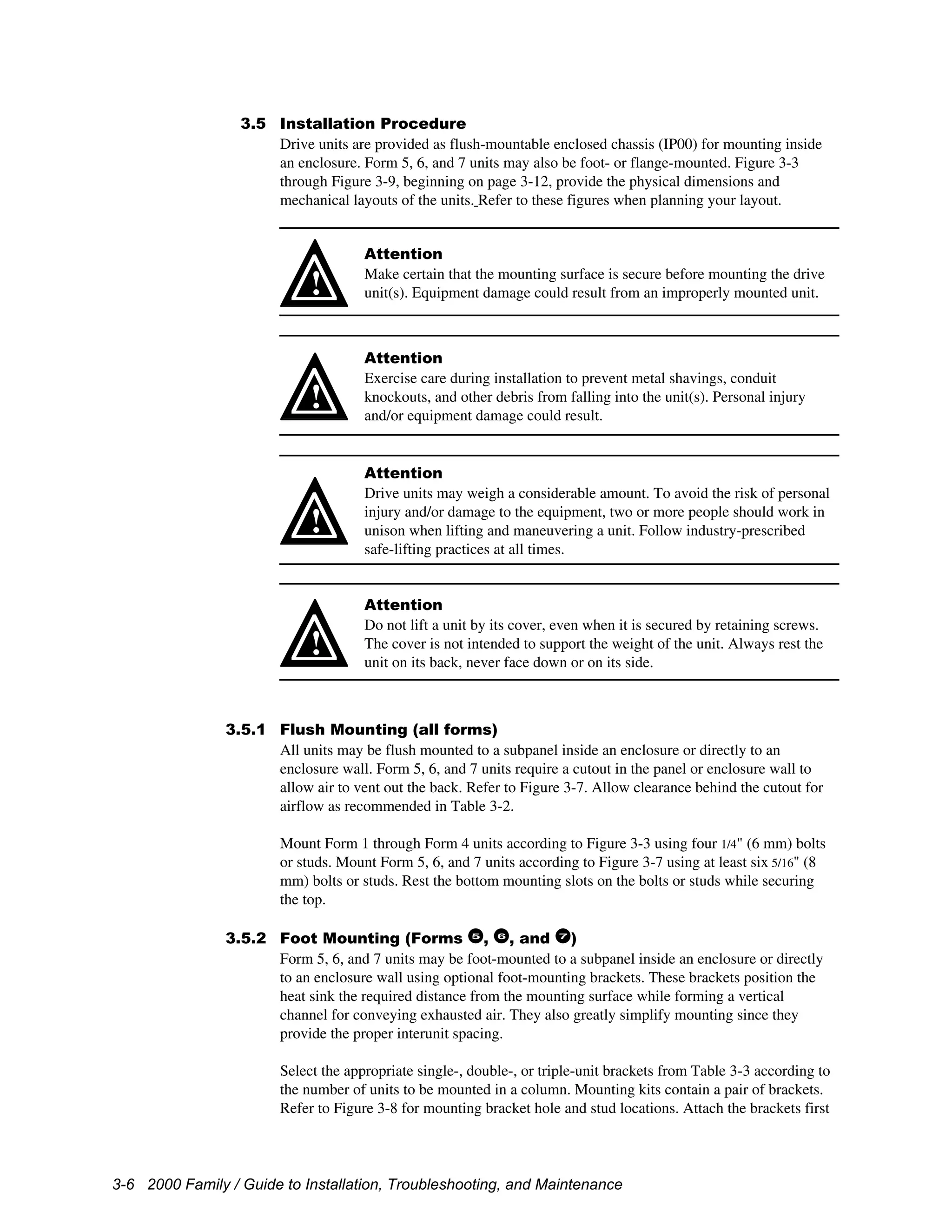
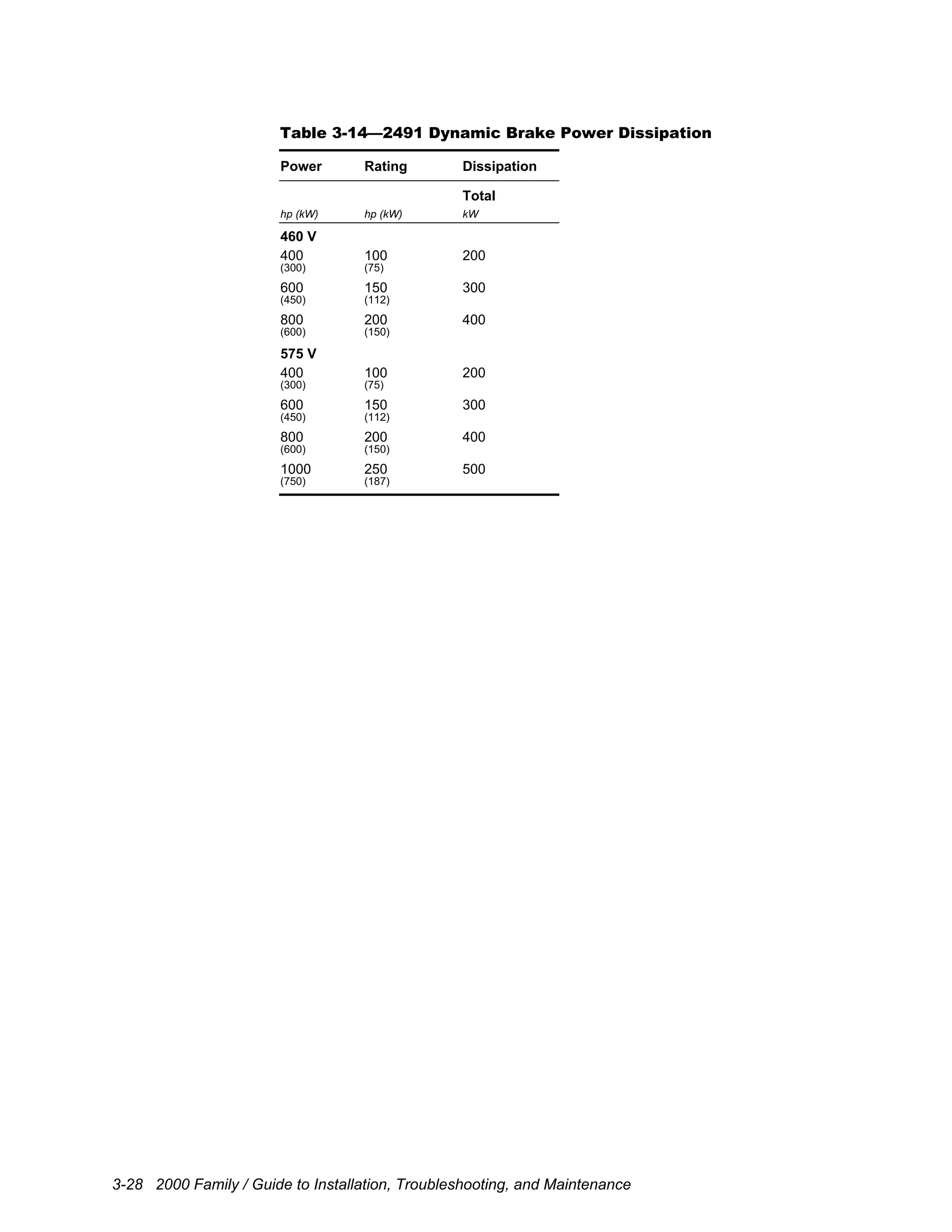
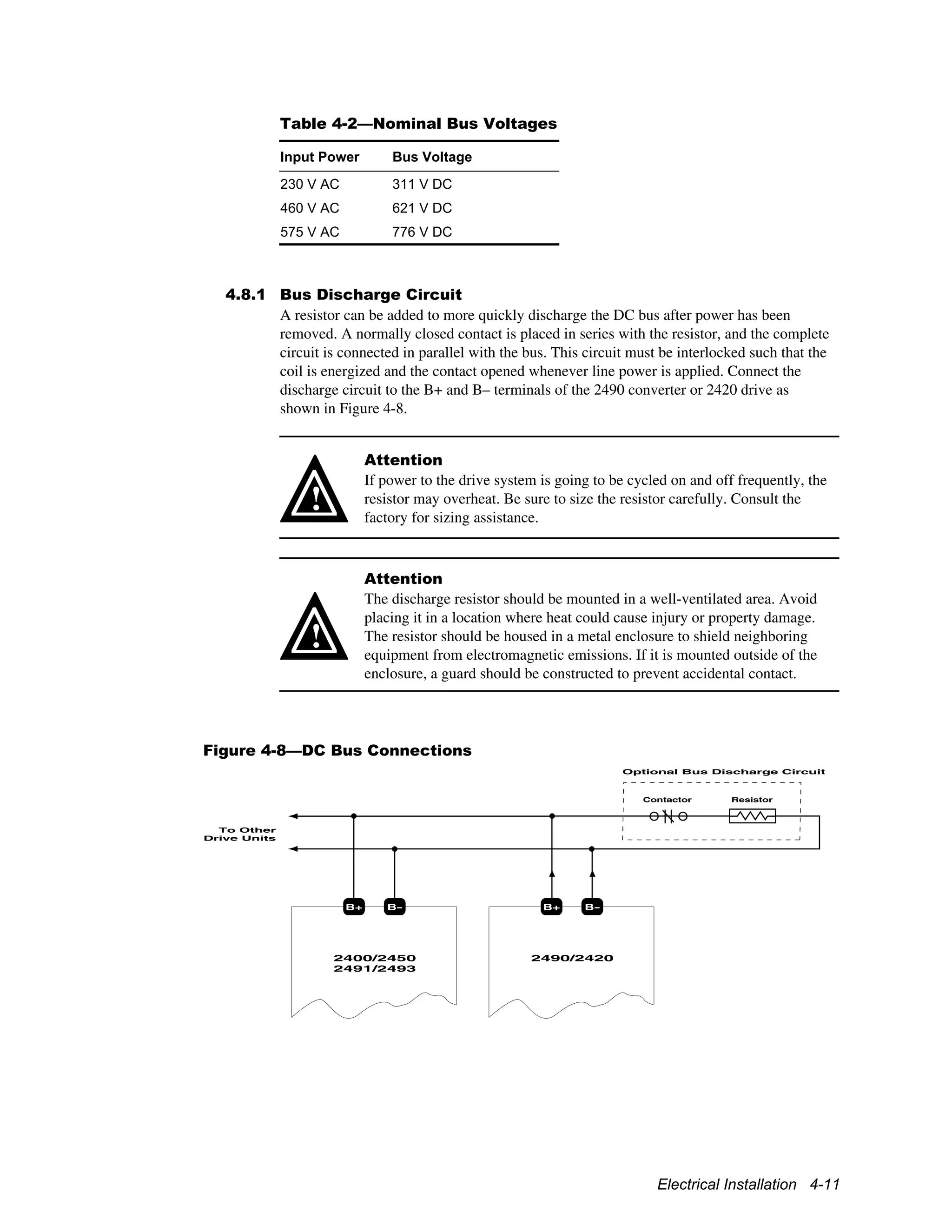
This document provides a guide to installing, troubleshooting, and maintaining UNICO 2000 family performance drives ranging from 1.1 to 975 kW (11 to 1300 hp). It covers unpacking and inspecting drives, an overview of drive features and architecture, specifications, mechanical installation including site considerations and procedures, electrical installation including grounding, power and signal connections, and maintenance precautions. The document is intended for installation and maintenance personnel working with these drives.