Download to read offline

![PEC / CSE OOAD/ UNIT-IV
30
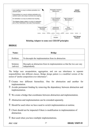
this.workShop1 = workShop1;
this.workShop2 = workShop2;
}
abstract public void manufacture();
}
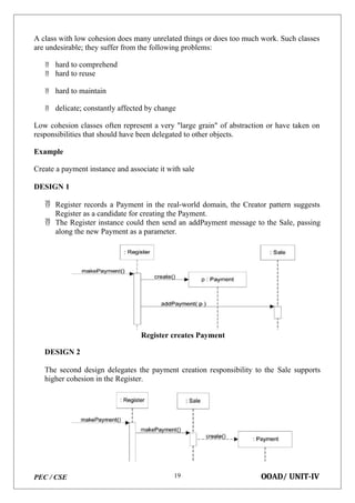
// Refine abstraction 1 in bridge pattern
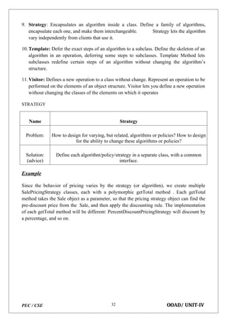
public class Car extends Vehicle {
public Car(Workshop workShop1, Workshop workShop2) {
super(workShop1, workShop2);
}
public void manufacture() {
System.out.print("Car ");
workShop1.work();
workShop2.work();
} }
public class Bike extends Vehicle {
public Bike(Workshop workShop1, Workshop workShop2) {
super(workShop1, workShop2);
}
public void manufacture() {
System.out.print("Bike ");
workShop1.work();
workShop2.work();
} }
// Implementor for bridge pattern
public interface Workshop {
abstract public void work();
}
//Concrete implementation 1 for bridge pattern
public class Produce implements Workshop {
public void work() {
System.out.print("Produced"); }}
public class Assemble implements Workshop {
public void work() {
System.out.println(" Assembled.");
}}
//Demonstration of bridge design pattern
public class BridgePattern {
public static void main(String[] args) {
Vehicle vehicle1 = new Car(new Produce(), new Assemble());
vehicle1.manufacture();
Vehicle vehicle2 = new Bike(new Produce(), new Assemble());
vehicle2.manufacture();
}
}](https://image.slidesharecdn.com/21cs1501objectorientedanalysisanddesignunitivnotes-250819054747-d86000b9/85/21CS1501-OBJECT-ORIENTED-ANALYSIS-AND-DESIGN-UNIT-IV-NOTES-docx-30-320.jpg)

A distributed database is defined as a collection of multiple, logically interrelated databases spread across a computer network. A distributed database management system (distributed DBMS) is the software that manages this distributed database, making its distribution transparent to users. The term "distributed database system" (DDBS) is often used to refer to both the distributed database and the distributed DBMS collectively.